


1
TABLE OF CONTENTS
General Information . . . . . . . . . . . . . . . . . . . . . . . . . . . . . . . . . . . . . . 2
Specifications . . . . . . . . . . . . . . . . . . . . . . . . . . . . . . . . . . . . . . . . . . . 2
Difference Specifications. . . . . . . . . . . . . . . . . . . . . . . . . . . . . . . . . . . 4
Features. . . . . . . . . . . . . . . . . . . . . . . . . . . . . . . . . . . . . . . . . . . . . . . 5
Manual Addenda. . . . . . . . . . . . . . . . . . . . . . . . . . . . . . . . . . . . . . . . . 5
Unpacking and Inspection. . . . . . . . . . . . . . . . . . . . . . . . . . . . . . . . . . 5
Safety Information. . . . . . . . . . . . . . . . . . . . . . . . . . . . . . . . . . . . . . . . 6
Safety Precautions . . . . . . . . . . . . . . . . . . . . . . . . . . . . . . . . . . . . . . . 6
Battery Installation/Replacement. . . . . . . . . . . . . . . . . . . . . . . . . . . . . 8
Memory Backup . . . . . . . . . . . . . . . . . . . . . . . . . . . . . . . . . . . . . . . . . 9
Operation with Rechargeable Battery . . . . . . . . . . . . . . . . . . . . . . . . . 9
Operating Instructions. . . . . . . . . . . . . . . . . . . . . . . . . . . . . . . . . . . . . 9
1. Diagnostics. . . . . . . . . . . . . . . . . . . . . . . . . . . . . . . . . . . . . . . 9
2. Display Annunciators. . . . . . . . . . . . . . . . . . . . . . . . . . . . . . . . 11
3. Function Keys. . . . . . . . . . . . . . . . . . . . . . . . . . . . . . . . . . . . . 13
Service Information. . . . . . . . . . . . . . . . . . . . . . . . . . . . . . . . . . . . . . . 18
1. Calibration Procedure . . . . . . . . . . . . . . . . . . . . . . . . . . . . . . . 18
2. Disassembly Instructions. . . . . . . . . . . . . . . . . . . . . . . . . . . . . 19
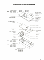
3. Mechanical Parts Diagram . . . . . . . . . . . . . . . . . . . . . . . . . . . 21
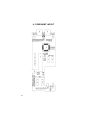
4. Component Layout . . . . . . . . . . . . . . . . . . . . . . . . . . . . . . . . . 22
5. Parts List . . . . . . . . . . . . . . . . . . . . . . . . . . . . . . . . . . . . . . . . 23
6. Schematic Diagrams. . . . . . . . . . . . . . . . . . . . . . . . . . . . . . . . 25
Warranty. . . . . . . . . . . . . . . . . . . . . . . . . . . . . . . . . . . . . . . . . . . . . . . 29
Limitation of Warranty. . . . . . . . . . . . . . . . . . . . . . . . . . . . . . . . . . . . . 29
Statement of Calibration . . . . . . . . . . . . . . . . . . . . . . . . . . . . . . . . . . . 29

2
GENERAL INFORMATION
This manual provides information on the use of three digital handheld ther-
mometers. Functional features both common and unique to each model are
described.
All three models are microprocessor based, and provide accurate and
reliable operation. They function with the most popular thermocouples; types
K, J, and T. A variety of features in these projects enhance their versatility,
while simplifying operation.
It is recommended that you read this manual thoroughly, especially the
sections on safety, prior to operating these instruments.
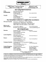
SPECIFICATIONS
THERMOCOUPLE INPUTS: 2 (T1, T2) miniature TC connectors.
Accepts male miniature and subminiature TC connectors.
THERMOCOUPLE TYPES: K, J, T
READOUT: T1, T2, T1-T2, and SCAN (T1, T2, T1-T2).
ACCURACY: (18°C to 28°C ambient, 2 years, excludes thermocouple error).
REPEATABILITY: ±0.2°C typical for 1 week at constant ambient temperature.
TEMPERATURE COEFFICIENT: 18°C to 28°C; included in accuracy specification.
From 0°C to 18°C, and 28°C to 50°C; less than ±(0.02% rdg + 0.1°C)/°C.
ENVIRONMENTAL LIMITS FOR OPERATING: 0°C to 50°C, less than 80% relative
humidity (R.H.) up to 35°C; reduce R.H. limit by 3%/°C from 35°C to 50°C.
ENVIRONMENTAL LIMITS FOR STORAGE: –35°C to 60°C, less than 90% relative
humidity (R.H.) up to 35°C; reduce R.H. limit by 3%/°C from 35°C to 60°C.
INPUT CURRENT: 50 nA typical.
READING RATE: (T1, T2, T1-T2); 1 reading/second typical, all parameters.
TC Extended Temp.
Type Range Resolution Accuracy (T1, T2) Accuracy (T1-T2) Range Acc’y (T1, T2), Typ.
K –200°C to 1372°C 0.1/1°C ±(0.1% rdg + 0.6°C) Acc’y (T1) + Acc’y (T2) –200°C to –250°C, ±(3°C)
–328°F to 2502°F 0.1/1°F ±(0.1% rdg + 1.0°F) Acc’y (T1) + Acc’y (T2) –328°F to –418°F, ±(5°F)
J –210°C to 760°C 0.1/1°C ±(0.1% rdg + 0.6°C) Acc’y (T1) + Acc’y (T2) —
–346°F to 1400°F 0.1/1°F ±(0.1% rdg + 1.0°F) Acc’y (T1) + Acc’y (T2) —
T –200°C to 400°C 0.1/1°C ±(0.1% rdg + 0.6°C) Acc’y (T1) + Acc’y (T2) –200°C to –250°C, ±(3°C)
–328°F to 752°F 0.1/1°F ±(0.1% rdg + 1.0°F) Acc’y (T1) + Acc’y (T2) –328°F to –418°F, ±(5°F)

3
MAXIMUM COMMON MODE VOLTAGE: 42V peak to earth.
POWER: 9 volt transistor battery (NEDA 1604).
BATTERY LIFE, CONTINUOUS: 50 hrs typical, carbon-zinc; 100 hrs typical, alkaline;
200 hrs typical, lithium; 15 hrs typical, Ni-Cd (rechargeable).
BATTERY INDICATOR: Display indicates BAT when less than 10% of life remains.
DISPLAY: 5 digit LCD, 0.4" height. Polarity indication, and decimal point.
Annunciators
• Readout Parameter: T1, T2, T1-T2, SCAN
• Record Parameter: MIN or MAX (when viewing recorded data).
• Readout Scale: °F, °C
• TC Type: K, J, T
• Hold (when activated)
• Reading Trend: up-arrow for increasing readings, down-arrow for decreasing
readings. Both arrows on for stable reading.
• Record MIN/MAX readings for T1, T2, and/or T1-T2; Flashing annunciator indi-
cates data being collected. Steady annunciator indicates data available, but not
being up-dated.
KEYPAD: 9 momentary switches with tactile feedback select;
• Power ON/OFF
• Readout: T1, T2, T1-T2, or SCAN
• TC type: K, J, T
• Readout scale: °F/°C
• Resolution: 0.1°/1°
• Display Hold
• Record MIN/MAX
• View MIN/MAX
• Stop recording MIN/MAX (first keystroke), clear recorded MIN/MAX (second
keystroke)
POWER OFF CONFIGURATION RETENTION: Instrument retains last selected;
• Readout: T1, T2, T1-T2, SCAN
• TC type: K, J, T
• Resolution: 0.1°/1°
• Scale: °F/°C
DIAGNOSTICS: Display codes indicate the following conditions:
• Low Battery: ‘BAT’
• Open Thermocouple(s): ‘OPEN’
• Invalid Keypad Entry: Momentary ‘E-1’
• Temperature Reading exceeds TC Rating: ‘E-2’
• Internal Hardware Fault: ‘E-3’ (consult factory)
• LCD Test: During power-up, all segments/annunciators turned on momentarily.
ELECTROMAGNETIC COMPATIBILITY: Add ±0.5% of range to accuracy specific-
tions for RF fields up to 1 volt/meter. Accuracy not specified for fields greater than
1 volt/meter.
DIMENSIONS, WEIGHT: 7.0" x 2.9" x 1.1". Net weight 10 oz.

4
DIFFERENCE SPECIFICATIONS
MODEL HH-21:
THERMOCOUPLE INPUTS: 1
DISPLAY: 5 digit LCD, 0.4" height. Polarity indication, and decimal point.
Annunciators
• Readout Scale: °F, °C
• TC Type: K, J, T
• Hold (when activated)
KEYPAD: 5 momentary switches with tactile feedback select;
• Power ON/OFF
• TC type: K, J, T
• Readout scale: °F/°C
• Resolution: 0.1°/1°
• Display Hold
POWER OFF CONFIGURATION RETENTION: Instrument retains last
selected;
• TC type: K, J, T
• Resolution: 0.1°/1°
• Scale: °F/°C
MODEL HH-22:
THERMOCOUPLE TYPES: K, J

5
FEATURES
• Temperature trend indication (rising, falling, or stable)
• Full range resolution of 0.1 degree
• Work with thermocouple types K, J and T
• Kpad selectable °F or °C
• Two probe inputs (for two point temperature measurements)
• Calculates and displays temperature difference between the two probe
inputs
• Maximum and minimum temperature storage
• Dust proof, splash proof, drop proof construction
• Built-in tilt stand/hanger for bench use or hands free field measurements
• User friendly function programming
• Performs self diagnostic test and displays error readout
• Retains function settings, even when turned off
• Low battery and open sensor indication
• Input data scan and display hold modes
MANUAL ADDENDA
Improvements or changes to this manual will be explained on an addendum
included with the instrument. All change information should be incorporated
immediately into the appropriate places in the manual.
UNPACKING AND INSPECTION
Each instrument is inspected both mechanically and electrically before ship-
ment. Upon receiving your instrument unpack all items from the shipping
container and check for any obvious damage that may have occurred during
transit. Report any damage to the shipping agent. Retain and use the origi-
nal packing materials if reshipment is necessary.

6
SAFETY INFORMATION
SAFETY SYMBOLS AND TERMS
The symbol on the instrument denotes that the user should refer to the
operating instructions.
The WARNING used in this manual explains dangers that could result in
personal injury or death.
The CAUTION used in this manual explains hazards that could damage
the instrument.
SAFETY PRECAUTIONS
WARNING
These instruments are intended for use by qualified per-
sonnel trained in the safe operation of electronic testing
equipment. Read the instruction manual thoroughly before
using, to become familiar with the instrument’s operations
and capabilities.
WARNING
Do not touch a temperature probe sheath when measuring
excessively high or low temperatures, or toxic substances.
WARNING
Do not attempt to measure temperatures beyond the range
of the probe being used. Probe damage or personal injury
could result from exceeding a probe’s maximum tempera-
ture rating.
WARNING
The American National Safety Institute (ANSI) states that a
shock hazard exists when probes or sensors are exposed
to voltage levels greater than 42VDC or 42V peak AC. Do
not use this instrument where voltages at the measure-
ment surface exceed these levels.
▲▲
!

7
WARNING
Do not substitute a metal part for the nylon screw in the
rear case. Doing so will degrade electrical isolation of the
case.
WARNING
The battery is accessible through a cover on the back of
the instrument. To avoid electrical shock hazard, discon-
nect all temperature probes and sensors and turn the unit
off before removing the cover.
WARNING
Never use this instrument or any probe or sensor inside a
microwave oven.
CAUTION
Avoid making sharp bends in probe or sensor lead wires.
Bending lead wires at a sharp angle can damage the wire
causing probe failure.
CAUTION
When using both thermometer inputs, and a voltage differ-
ential exists between the two measurement points, at least
one probe should be electrically insulated. If not, ground-
loop current can flow through the thermocouple leads
causing measurement error or instrument damage.

8
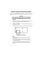
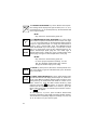
BATTERY INSTALLATION/REPLACEMENT
A 9V battery is supplied with the instrument but not installed. Read the fol-
lowing installation instructions before attempting to install or remove the bat-
tery.
WARNING
Turn the unit off and disconnect any input connections
before replacing the battery. Put the cover back into place
on the battery compartment before resuming use of the
instrument.
1. Remove the cover from the battery compartment by sliding it off in
the direction of the arrow located on the battery cover.
2. Remove the old battery.
3. Place the new battery in the battery compartment. Be sure to
observe proper polarity.
4. Re-install the battery cover before resuming use of the instrument.
NOTES:
• Less than 10% of battery life remains when the BAT annun-
ciator turns on.
• If the instrument is going to be stored for a long period of time
or in a high temperature environment, remove the battery to
prevent leakage damage.
• After a new battery is installed, allow approximately 30 sec-
onds for reading stabilization the first time the instrument is
turned on.
Figure 1. Battery Installation


10
MEMORY BACKUP
During battery replacement, the contents of user-programmed memory
(data, operating modes, etc.) can be saved. Prior to removing the old battery,
turn off the instrument, and connect a Model 80010 battery charger. Then
exchange batteries, and disconnect the battery charger. Do not leave the bat-
tery charger connected to instruments with non-rechargeable batteries.
OPERATION WITH RECHARGEABLE
BATTERY
Model 80010 provides a 9-volt Ni-Cd battery and recharger suitable for use
with the unit. This battery provides 15 hours of continuous operation. This
duration can be extended indefinitely by operating simultaneously from both
the battery and recharger.
OPERATING INSTRUCTIONS
The following instructions make reference to keypad inputs, and display
readouts. Refer to Figure 2 to locate key switches, and identify display dif-
ferences between thermometer models. Model HH-22 is similar in layout to the
HH-23, except operation is limited to K and J thermocouples.
1. DIAGNOSTICS
Automatic diagnostics provide error indicators which are described below.
PROBLEM: LIKELY CAUSE:
Blank display, unit does not (1) Improper battery installation. Check
power-up. battery polarity.
(2) Dead battery.
Low BAT Annunciator. (1) Low battery voltage, install a new
battery. If problem persists, consult
factory.

11
Display reads (1) No thermocouple or a damaged ther-
mocouple is plugged into the selected
input.
NOTE: When viewing T1-T2, there
must be a thermocouple plug-
ged into both input jacks.
Display reads momentarily. (1) This indicates that an invalid entry has
been made. Review keystroke se-
quence, or consult manual for input
instructions.
Display reads during (1) This indicates the temperature range
temperature measurement. has been exceeded for this thermo-
couple type. Remove thermocouple
from temperature source.
WARNING
Do not touch the probe sheath
when measuring excessively
high or low temperatures.
WARNING
Probe damage and personal
injury could result from exceed-
ing a probe’s maximum tempera-
ture ratings.
2. DISPLAY ANNUNCIATORS
Each item on the display (Figure 2) is described below in detail. To better
familiarize yourself with the thermometer’s display annunciators, please read
this section.
1. Input Selection Annunciator
This annunciator will indicate which input is being monitored.
— thermocouple T1
— thermocouple T2
— the difference between the two thermocouples T1-T2
T1 T2 T1-T2
T1
T2
T1-T2

12
2. Record Annunciator
A flashing record symbol adjacent to a corresponding input selection
annunciator indicates that this channel is being recorded. A static record
symbol indicates data has been recorded, but is not being updated.
3. Trend Indication Annunciators
When the up-arrow is displayed, the reading is increasing.
When the down-arrow is displayed, the reading is decreasing.
When both arrows are displayed, the reading is stable.
When the second arrow is flashing on and off — the sensor is approach-
ing a stable reading.
4. BAT Low Battery Annunciator
This symbol appears when less than 10% of battery life remains.
5. K J T Thermocouple Type Annunciator
These symbols indicate the thermocouple type selection.
NOTE: To insure correct temperature readings, the displayed
thermocouple type must match the thermocouple
used.
6. Numeric Display
The 5 digit numeric display indicates the temperature of the selected
thermocouple, T1 or T2, or T1-T2.
7. °C, °F Temperature Scale Annunciators
The °C and °F symbols indicate whether the temperature readings are
displayed in degrees Celsius or degrees Fahrenheit.
8. MIN Minimum Annunciator
This symbol appears when the display is showing the minimum reading
stored while in the record mode.
9. MAX Maximum Annunciator
This symbol appears when the display is showing the maximum reading
stored while in the record mode.
R
E
C

13
10. HOLD Hold Annunciator
This symbol will indicate that the instrument display is on hold.
11. SCAN Scan Annunciator
This annunciator will be displayed when the instrument is sequentially
viewing T1, T2 and T1-T2.
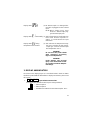
3. FUNCTION KEYS
The ON/OFF key turns the thermometer on or off. To turn the ther-
mometer on, press the ON/OFF Key once. All the display annun-
ciators and segments should turn on momentarily (see Figure 2)
for visual checking. During this period the thermometer performs
internal diagnostics.
Following display test, if no input thermocouple is connected to
the unit, the display will indicate “OPEN”.
Plugging a thermocouple into the appropriate TC connector will
give actual thermocouple temperature readings.
If the unit is turning on for the first time after installation of a new
battery, it will default to K-type thermocouples, and °F readings
with 0.1° resolution.
NOTE: To obtain full accuracy, allow 1-2 minutes
after connecting a thermocouple plug, for
thermal setting.
To turn the thermometer OFF, press the ON/OFF key a second
time.
The TEMPERATURE SCALE key selects whether temperature
readings will be displayed in degrees Fahrenheit or degrees
Celsius. Upon initial power-up, the thermometer will display read-
ings in degrees Fahrenheit. To display readings in degrees
Celsius, press the TEMPERATURE SCALE key. To change back
to degrees Fahrenheit, press the TEMPERATURE SCALE key a
second time.
NOTE:
• Key selection is retained during power off.
°F
°C
ON
OFF

14
The DISPLAY RESOLUTION key selects whether the tempera-
ture readings will be displayed in high resolution (0.1°C or °F) or
low resolution (1°C or °F). At initial power-up, the thermometer will
read in high resolution.
NOTE:
• Key selection is retained during power off.
The THERMOCOUPLE TYPE SELECTION key selects which
type of thermocouple the thermometer will be set up to use (Type
K, J or T). Upon initial power-up, the thermometer will be ready to
accept a K Type thermocouple. To change the thermometer to
accept a Type J thermocouple, press the THERMOCOUPLE
TYPE SELECTION key. Press the key a second time to select
Type T. To change back, press the key until desired type is dis-
played. Thermocouple probe plugs are color coded. Type K
Thermocouples have a yellow plug, Type J Thermocouples have
a black plug, and Type T Thermocouples have a blue plug.
NOTES:
• Key selection is retained during power off.
• To insure proper temperature readings, be sure
that the displayed thermocouple type matches
the type of thermocouple you are using.
The HOLD key, when pressed, will “freeze’’the temperature read-
ings on the display. To get out of the Hold mode, press the HOLD
key a second time.
The INPUT SELECTION/SCAN key selects which thermocouple
input the thermometer will display; thermocouple T1, thermocou-
ple T2 or the difference between thermocouples T1 and T2. Upon
initial power-up, the thermometer will default to channel T1. To
select channel T2, press the INPUT SELECTION key (input
selection annunciator will appear). To view the difference
between the two inputs, calculated as T1 minus T2, press the
INPUT SELECTION key a second time (input selection annunci-
ator will appear).
To scan inputs T1, T2, T1-T2, press the INPUT SELECTION/
SCAN key a third time. (The SCAN annunciator will then appear.)
The unit will then sequentially display the readings of T1, T2, and
T1-T2. To return to T1, press the key again.
T2
T1-T2
0.1°
1°
HOLD
T1 T2
T1-T2
KJ
T
SENSOR
SELECT
(or)

15
NOTE: The thermometer will display “OPEN” on
any selected channel that does not have a
thermocouple plugged in or if the thermo-
couple is open-circuited.
CAUTION
When using both thermocouple inputs, and a
voltage differential exists between the two mea-
surement points, at least one probe should be
electrically insulated.
NOTES:
• T1 and T2 are not measured simultaneously.
Therefore T1 and T2 readings can differ even
when the temperatures are equal, if T1 and T2
are changing rapidly.
• Key selection is retained during power off.
With the REC key, the recording of MIN/MAX temperatures is
enabled. This function can be activated in one or more of the 3
measurement modes, T1, T2, and T1-T2. To start recording,
select a desired measurement mode (T1, T2, or T1-T2), then
press REC.
When more than one measurement mode is to be recorded,
select the desired mode and then activate the record function.
When REC is activated, a corresponding annunciator(s) will turn
on and start flashing adjacent to the mode annunciator(s) (T1, T2,
T1-T2). The flashing REC annunciator means that minimum and
maximum data is being recorded. The instrument has 3 separate
acquisition files which allow simultaneous recording of all three
modes.
NOTE: REC cannot be started while the readout is
in the SCAN mode. However, after record-
ing is initiated, the readout can be set to the
SCAN mode.
REC

16
With the thermometer in either the T1, T2, or T1-T2 mode, corre-
sponding MIN/MAX data can be viewed. To view MIN/MAX data,
first select T1, T2, or T1-T2. Then press the VIEW key to read the
MAX temperature. A second press of the VIEW key will display
the MIN temperature. At the third press of the VIEW key, the dis-
play will go back to display the current temperature. To view a dif-
ferent input, select that input and repeat the procedure.
NOTES:
• MIN/MAX data can be viewed while recording is
in progress (ie, REC annunciator(s) flashing). In
this case, the VIEW function will display real-time
running values of MIN or MAX temperatures.
• MIN/MAX data can be viewed after data record-
ing is stopped. See STOP/CLR for instructions to
stop recording. In this case, the VIEW function
will display static data that does not update.
• The VIEW function cannot be initiated while the
readout is in the SCAN mode. For example, to
view the MAX value recorded for T2, first select
mode T2, then depress the VIEW key.
• After selecting parameters to view, it is possible
to go to the SCAN mode, and continue to view
these parameters.
Example:
While in mode T1, view MAX. Then select mode
T2, and view MIN. When SCAN is activated, the
readout will sequentially display T1(MAX),
T2(MIN), T1-T2. This is a very powerful tool for
analytical temperature analysis.
• If VIEW is enabled in a mode (T1, T2, or T1-T2)
that was not recorded, the MAX and MIN annun-
ciators will turn on as before. However, the
numeric readout will indicate the current temper-
ature. (Without RECORD being activated, the
current reading, the maximum and the minimum
readings are equivalent.)
VIEW

17
Recording in one or more of the three measurement modes T1,
T2, and T1-T2 can be stopped with this key. Before pressing CLR
this key, select the appropriate mode. When MIN/MAX data col-
lection is stopped, the corresponding REC annunciator will stop
flashing, but will remain on (to indicate that MIN/MAX data has
been saved for viewing). Recording can be re-started anytime
without loss of data with the REC key. See REC.
If the STOP/CLR key is pressed again (after stopping data
recording), MIN/MAX data for the corresponding measurement
mode is cleared, and the REC annunciator is turned off.
NOTES:
• MIN/MAX data is erased when the thermometer
is turned off.
• Record configurations are not saved during
power-off.
• STOP/CLR function cannot be performed while
the readout is in the SCAN mode. Select T1, T2,
and/or T1-T2 modes before attempting to stop
recording or clear data.
• The STOP/CLR key must be pressed twice to
clear recorded data, and will only clear data in the
TC mode that is active when the key is pressed.
STOP
CLR

18
SERVICE INFORMATION
WARNING
All service information is intended for qualified electronic
maintenance personnel only.
1. CALIBRATION PROCEDURE
Test Equipment Required:
1. Thermocouple calibrator (Omega CL521, or equivalent).
2. Calibration cable for each thermocouple type handled by unit under test
(U.U.T.):
Type K
Type J
Type T
Ambient Conditions:
Units should be calibrated at an ambient temperature of 23°C ±1°C, with rel-
ative humidity less than 80%. Avoid air currents and heat sources that can
disturb the thermal equilibrium of the U.U.T.
Procedure:
1. Turn OFF U.U.T.
2. Remove rear cover. Refer to Disassembly Instructions.
3. Remove shorting-plug J1 from circuit board. Refer to Mechanical Parts
Diagram for location (P/N CS-791).
4. Replace rear cover. Reinstall battery. Turn on U.U.T.
5. Connect input of U.U.T. to the thermocouple calibrator with a type K
cable. Use input T1 on Models HH-22 and HH-23.
6. Set calibrator output to 32°F, type K.
7. Wait for U.U.T. readout to stabilize, then press HOLD key once, and wait
a few seconds. U.U.T. should read 32.0°F ±0.5°F, type K.
8. Set calibrator to 2500°F, type K.
9. Wait for U.U.T. readout to stabilize, then press HOLD key once, and wait
a few seconds. U.U.T. should read 2500.0°F ±1.0°F, type K.
10. Replace type K cable with Type J.
11. Set calibrator output to 32°F, type J.
Page is loading ...
Page is loading ...
Page is loading ...
Page is loading ...
Page is loading ...
Page is loading ...
Page is loading ...
Page is loading ...
Page is loading ...
Page is loading ...
Page is loading ...
-
 1
1
-
 2
2
-
 3
3
-
 4
4
-
 5
5
-
 6
6
-
 7
7
-
 8
8
-
 9
9
-
 10
10
-
 11
11
-
 12
12
-
 13
13
-
 14
14
-
 15
15
-
 16
16
-
 17
17
-
 18
18
-
 19
19
-
 20
20
-
 21
21
-
 22
22
-
 23
23
-
 24
24
-
 25
25
-
 26
26
-
 27
27
-
 28
28
-
 29
29
-
 30
30
-
 31
31


Omega HH-21, HH-22, HH-23 User manual
- Category
- Measuring, testing & control
- Type
- User manual
Ask a question and I''ll find the answer in the document
Finding information in a document is now easier with AI
Related papers
-
Omega HH-21A, HH-22A, HH-23A Owner's manual
-
Omega Engineering HH64A User manual
-
-
-
-
-
-
-
-
Other documents
-
TFA Digital Professional Thermocouple Measuring Device MINI-K User manual
-
 Altronics Dual EGT Owner's manual
-
Tegam 821A User manual
-
 AND AX-MX-43 User manual
-
Dwyer CA10 User manual
-
Harbor Freight Tools Instant Read Digital Thermometer User manual
-
-
 Aqua Comfort ACT Signature Series Calibrations And Settings
-
Traceable 4135 Owner's manual
-
 ThermoMart Digital Thermometer DM6802A+ Owner's manual


