2
30000275
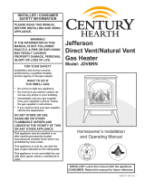
Fig. 4 Attach the Rheostat to the Control Panel.
Rheostat
Retaining Nut
Control Knob
Control Panel
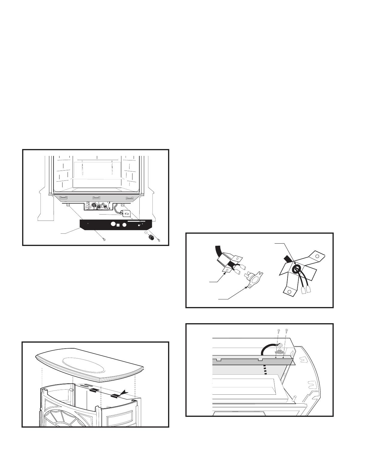
Cut pad
to size
and
locate as
needed
Fig. 5 Vibration dampening pad location. (PDV20 shown)
4. The Rheostat Control switch attaches to the Control
Panel plate provided in the parts bag with the stove.
• Insert the switch box shaft through the hole in the
back of the right side of the Panel, aligning the loca-
tor pin with the smaller hole in the panel. (Fig. 4)
• Attach the Retaining Nut to the switch control shaft
to secure it to the plate.
• Attach the Control Knob to the rheostat shaft.
• Use the wire tie to secure the fan and rheostat wire
harnesses together to the tubing under the bottom
heat shield.
Do not install the Control Panel onto the stove until
after the gas supply and valve wiring connections have
been made. See Assembly Instructions, PDV20/SDVR
Owner’s Guide.
5. A length of silicone tape is included for installation
between the Top Plate and the Rear Shroud, should
you find that contact between these two surfaces
causes vibration while the fan is operating.
• Remove the Top Plate.
• Cut the self-adhesive tape to size as needed,
remove the backing paper and place tape on the top
edge of the Shroud at those locations where it will
eliminate direct contact between the Shroud and the
Top Plate. (Fig. 5)
• Replace the Top Plate.
Fig. 7 Attach snapstat to inner shroud.
UVS27 Installation Procedure
– for Stardance and Pinnacle Vent-Free
1. Attach the Fan assembly to the rear shroud in the
same manner as detailed in the preceding section for
the PDV20/SDVR, following Step 3, Figures 2-3.
2. Disconnect the snapstat module from the leads
inside the snapstat bracket. (Fig. 6)
3. Bend open the snapstat bracket. Use your fingers
or needle nose pliers to remove the black plastic
grommet from the bracket. Discard the grommet and
bracket.
4. Feed the snapstat wire lead up between the in-
ner and outer rear shroud panels and secure the
snapstat to the upper right side of the inner shroud.
(Fig. 7)
5. Secure the snapstat wire harness to the shroud panel
using the wire tie provided with this kit.
6. Route the rheostat control switch and wire forward
under the stove. Use the wire tie to secure the fan
and rheostat wire harnesses together to the tub-
ing under the bottom heat shield.
UVS27R / Honeywell Millivolt Valve: Install the
rheostat onto the control panel at the hole to the
right of the valve, as in Figure 4.
UVS27M / SIT Manual Valve: Install the rheostat onto
the bracket to the left of the valve.
ST468
remove
snapstat grommet
9/28/00 djt
Snapstat
Bracket
Snapstat
Module
Pinch Grommet
to Remove
ST468
Fig. 6 Remove snapstat and grommet from bracket.