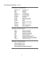
Simplex 4100U User manual
- Category
- Fire protection
- Type
- User manual
This manual is also suitable for

Fire
Australian
Installation
Manual
4100U Fire Indicator Panel
Fire Alarm System, Installation &
Maintenance
Australian
Installation &
Maintenance
Manual
LT0350


i
2004 Tyco Safety Products Westminster,
Westminster, MA 01441-0001 USA.
All specifications and other information shown were current as of document revision date,
and are subject to change without notice.
Tyco, Simplex, the Simplex logo, MAPNET II, IDNet, TrueAlarm, SmartSync,
WALKTEST, MINIPLEX, and TrueAlert are trademarks of Tyco International Services
AG or its affiliates in the U.S. and/or other countries. VESDA is a trademark of Vision
Products Pty Ltd.
Simplex fire alarm technology is protected by the following U.S. Patent Numbers:
TrueAlarm analog smoke detection: 5,155,468; 5,173,683 and 5,543,777. IDNet and
MAPNET II addressable communications; 4,796,025. TrueAlert addressable notification;
6,313,744 and 6,426,697. SmartSync horn/strobe control; 6,281,789.
Australian Standard AS4428.1
SSL Listing Number afp1682
The 4100U is a Fire Alarm manufactured by Tyco Safety Products for:
Tyco Services Fire & Safety
47 Gilby Road
Notting Hill
VIC 3168
AUSTRALIA
Phone : (03) 9538-7220
Fax : (03) 9538-7255
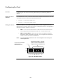
Name
Serial #
Manufacture Date
Copyrights and Trademarks
Approvals
Manufacture
Product / Site

ii
Tyco (THE COMPANY) and the User of this/these document(s) desire to share
proprietary technical information concerning electronic systems.
For this reason the company is disclosing to the User information in the form of this/these
document(s). In as much as the company considers this information to be proprietary and
desires that it be maintained in confidence, it is hereby agreed by the User that such
information shall be maintained in confidence by the User for a period of TEN YEARS
after the issue date and only be used for the purpose for which it was supplied.
During this period, the User shall not divulge such information to any third party without
the prior written consent of the company and shall take reasonable efforts to prevent any
unauthorised disclosure by its employees. However, the User shall not be required to
keep such information in confidence if it was in their possession prior to its receipt from
the company; if it is or becomes public knowledge without the fault of the User; or the
information becomes available on an unrestricted basis from a third party having a legal
right to disclose such information.
The User's receipt and retention of this information constitutes acceptance of these terms.
This information is copyright and shall not be reproduced in any form whatsoever.
The 4100U Fire Indicator Panel provides a configuration programming facility, which
may be accessed via a programming computer using a “dongle”. Because this
programming facility allows the user to define in detail the operation of the 4100U
System being customised, changes may be made by the user that prevent this installation
from meeting statutory requirements.
The Company, therefore cannot accept any responsibility as to the suitability of the
functions generated by the user using this programming facility.
Non-Disclosure Agreement
End User Liability Disclaimer

iii
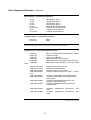
This manual applies to product with the following:
Model number : 4100U
Firmware revision : 11.08 and on
Document Name : LT0350 4100U Installation & Maintenance Manual
Cross Reference : 574-848 4100U Installation Manual (USA)
Issue : 1.0-G 14 May, 2004
14 May, 2004 Issue 1.0.6 Original based on 574-848 Rev G
Model Number & Firmware Revision
Document
Amendment Log

iv
READ AND SAVE THESE INSTRUCTIONS. Follow the instructions in this
installation manual. These instructions must be followed to avoid damage to this product
and associated equipment. Product operation and reliability depends upon proper
installation.
DO NOT INSTALL ANY SIMPLEX
®
PRODUCT THAT APPEARS DAMAGED.
Upon unpacking your Simplex product, inspect the contents of the carton for shipping
damage. If damage is apparent, immediately file a claim with the carrier and notify your
Simplex product supplier.
SAFETY HAZARD - The 4100U CPU Card includes a lithium battery. There is
danger of explosion if the battery is incorrectly replaced. Replace only with the same
or equivalent type recommended by the manufacturer. Dispose of used batteries
according to the manufacturer’s instructions.
ELECTRICAL HAZARD - Disconnect electrical field power when making any internal
adjustments or repairs. All repairs should be performed by a representative or authorized
agent of your local Simplex product supplier.
STATIC HAZARD - Static electricity can damage components. Therefore, handle as
follows:
• Ground yourself before opening or installing components (use the 553-484 Static
Control Kit).
• Prior to installation, keep components wrapped in anti-static material at all times.
EYE SAFETY HAZARD - Under certain fiber optic application conditions, the optical
output of this device may exceed eye safety limits. Do not use magnification (such as a
microscope or other focusing equipment) when viewing the output of this device.
RADIO FREQUENCY ENERGY - This equipment generates, uses, and can radiate
radio frequency energy and if not installed and used in accordance with the instruction
manual, may cause interference to radio communications. It has been tested and found to
comply with the limits defined in AS4428.0-1997 and Amendment 1 : 2002.
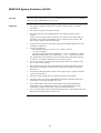
SYSTEM REACCEPTANCE TEST AFTER SOFTWARE CHANGES - To ensure
proper system operation, this product must be tested in accordance with AS1670 after any
programming operation or change in site-specific software. Reacceptance testing is
required after any change, addition or deletion of system components, or after any
modification, repair or adjustment to system hardware or wiring.
All components, circuits, system operations, or software functions,known to be affected
by a change must be 100% tested. In addition, to ensure that other operations are not
inadvertently affected, at least 10% of initiating devices that are not directly affected by
the change, up to a maximum of 50 devices, should also be tested and proper system
operation verified.
IMPORTANT: Verify 4100U System Programmer, Executive, and Slave Software
compatibility when installing or replacing system components. Refer to Solution Bulletin
SB01014 for compatibility information.
Cautions, Warnings, and Regulatory Information

v
Copyrights and Trademarks ................................................................................ i
Approvals............................................................................................................. i
Manufacture......................................................................................................... i
Product / Site ....................................................................................................... i
Non-Disclosure Agreement .................................................................................ii
End User Liability Disclaimer...............................................................................ii
Model Number & Firmware Revision..................................................................iii
Document ...........................................................................................................iii
Amendment Log .................................................................................................iii
Cautions, Warnings, and Regulatory Information...............................................iv
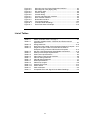
Table of Contents ............................................................................................... v
List of Figures ...................................................................................................xiv
List of Tables .....................................................................................................xv
Chapter 1 Introduction to the 4100U Fire Alarm System ........ 1-1
Introduction ..................................................................................................1-1
In this Chapter .............................................................................................1-1
System Configurations ....................................................................................1-2
Overview......................................................................................................1-2
Standalone Configuration ................................................................................1-3
Overview......................................................................................................1-3
System Design............................................................................................. 1-3
MINIPLEX Configuration ................................................................................. 1-4
Overview......................................................................................................1-4
System Design............................................................................................. 1-4
RUI Communication..................................................................................... 1-5
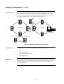
Network Configuration .....................................................................................1-6
Overview......................................................................................................1-6
Hub and Star Configurations ....................................................................... 1-6
Connecting Loops........................................................................................ 1-7
System Design............................................................................................. 1-7
Network Communication.............................................................................. 1-7
4100 PIDs (Non-4100U) ..................................................................................1-8
Annunciation Modules .................................................................................1-8
4100U Cabinet Part Identification Numbers (PIDs).........................................1-9
Overview......................................................................................................1-9
4100U Cabinets ........................................................................................... 1-9
Table of Contents

vi
4100U PIDs .....................................................................................................1-9
Overview......................................................................................................1-9
Assemblies, Cards & & Modules .................................................................1-9
Kits .............................................................................................................1-10
Labels ........................................................................................................1-10
Looms ........................................................................................................1-10
Chapter 2 Installing 4100U FACP Components ....................... 2-1
Introduction ..................................................................................................2-1
In this Chapter .............................................................................................2-1
Introduction to FACPs (4100U) .......................................................................2-2
Overview......................................................................................................2-2
CPU Bay ...................................................................................................... 2-2
Master Motherboard ....................................................................................2-3
Master Controller Daughter Card ................................................................2-4
Master Controller Daughter Card LEDs....................................................... 2-5
Operator Interface........................................................................................ 2-6
Additional CPU Bay Modules .....................................................................2-6
Expansion Bays ........................................................................................... 2-6
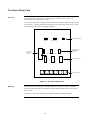
System Power Supply (SPS)....................................................................... 2-7
System Power.............................................................................................. 2-8
The Power Distribution Interface (PDI)........................................................2-8
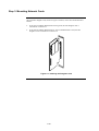
Step 1. Mounting Cabinets (4100U) ................................................................ 2-9
Overview......................................................................................................2-9
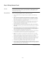
Step 2. Mounting Card Bays to Cabinets (4100U) ..........................................2-9
Overview......................................................................................................2-9
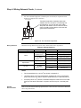
Step 3. Configuring Cards (4100U) ............................................................... 2-10
Overview....................................................................................................2-10
Master Motherboard Configuration............................................................2-10
Master Controller Daughter Card Configuration........................................2-10
SPS Configuration .....................................................................................2-10
PDI Configuration ......................................................................................2-11
Configuring Other Cards............................................................................2-11
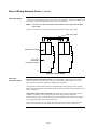
Step 4. Interconnecting Modules and Bays................................................... 2-11
Overview....................................................................................................2-11
Guidelines..................................................................................................2-11
Card Interconnections in the CPU Bay...................................................... 2-12
Card Interconnections Within Expansion Bays .........................................2-12
Basic Bay-To-Bay Interconnections ..........................................................2-12
Connecting to Motherboards .....................................................................2-13
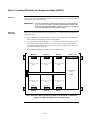
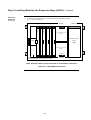
Step 5. Installing Modules into Expansion Bays (4100U) .............................2-15
Overview....................................................................................................2-15
Placement Guidelines................................................................................2-15
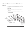
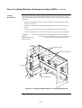
Installing 4” X 5” Cards .............................................................................. 2-18

vii
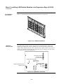
Step 6. Installing LED/Switch Modules into Expansion Bays (4100U).......... 2-20
Overview....................................................................................................2-20
The LED/Switch User Interface ................................................................. 2-21
LED/Switch Controller Card.......................................................................2-21
LED/Switch Modules.................................................................................. 2-22
Configuring the LED/Switch Controller Card .............................................2-22
Activating the Communication Loss Feature............................................. 2-22
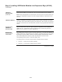
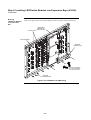
Mounting LED/Switch Modules to the Expansion Bay ..............................2-23
Mounting the Controller Card Assembly.................................................... 2-24
Changing Display Card LEDs....................................................................2-24
Interconnecting Cards................................................................................ 2-25
Wiring Instructions .....................................................................................2-26
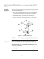
The Terminal Block Utility Module (4100U)...................................................2-27
Overview....................................................................................................2-27
Mounting to the Electronics Bay ................................................................ 2-27
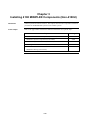
Chapter 3 Installing 4100 MINIPLEX Components
(Non-4100U) ................................................... 3-29
Introduction ................................................................................................3-29
In this Chapter ...........................................................................................3-29
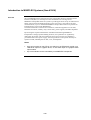
Introduction to MINIPLEX Systems (Non-4100U) .........................................3-30
Overview....................................................................................................3-30
MINIPLEX System Components (Non-4100U) .............................................3-32
Overview....................................................................................................3-32
The RUI Card.............................................................................................3-32
Transponder Cabinets ............................................................................... 3-32
The Remote Interface Card (RIC) .............................................................3-33
MINIPLEX System Guidelines (Non-4100U)................................................. 3-34
Overview....................................................................................................3-34
Guidelines..................................................................................................3-34
Installing Modules into Cabinets (Non-4100U)..............................................3-35
Overview....................................................................................................3-35
Guidelines..................................................................................................3-35
Installing the RUI Motherboard................................................................. 3-35
Installing the RIC II Motherboard...............................................................3-36
Connecting the 733-525 Harness............................................................. 3-37
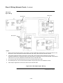
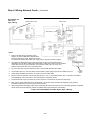
MINIPLEX Wiring (Non-4100U).....................................................................3-39
Overview....................................................................................................3-39
Wiring Configurations ................................................................................3-39
Class A Wiring ........................................................................................... 3-39
Class B Wiring ........................................................................................... 3-39
Wiring Illustration .......................................................................................3-40
Chapter 4 Installing 4100U MINIPLEX Components ................ 4-1
Introduction ..................................................................................................4-1
In this Chapter .............................................................................................4-1
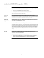
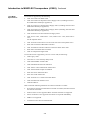
Introduction to MINIPLEX Transponders (4100U)........................................... 4-2
Overview......................................................................................................4-2
Transponder Cabinets ................................................................................. 4-2
Transponder Interface Cards (TICs)............................................................4-2
Basic TICs ...................................................................................................4-2
The Local Mode TIC (Not currently available in Australia). ......................... 4-3
TIC Illustrations............................................................................................ 4-4

viii
Local Mode Specifications........................................................................... 4-5
LEDs ............................................................................................................4-6
Card Specifications...................................................................................... 4-6
MINIPLEX System Guidelines (4100U)...........................................................4-7
Overview......................................................................................................4-7
Guidelines.................................................................................................... 4-7
Configuring Cards (4100U).............................................................................. 4-8
Overview......................................................................................................4-8
CPU Motherboard DIP Switch ..................................................................... 4-8
TIC Configuration......................................................................................... 4-8
Configuring Other Cards..............................................................................4-8
TIC/Riser Mounting (4100U)............................................................................ 4-9
Overview......................................................................................................4-9
Mounting Instructions...................................................................................4-9
TIC/Motherboard Interconnections (4100U)..................................................4-10
RUI Wiring (4100U) .......................................................................................4-11
Overview....................................................................................................4-11
Wiring Configurations ................................................................................4-11
Chapter 5 Networking ................................................................ 5-1
Introduction ..................................................................................................5-1
In this Chapter .............................................................................................5-1
Getting Started.................................................................................................5-2
Overview......................................................................................................5-2
Introduction to the 4100 Network Interface Card (NIC)................................... 5-3
Overview......................................................................................................5-3
Network Module Illustrations .......................................................................5-4
NIC Card LED Indications............................................................................5-4
NIC Motherboards .......................................................................................5-5
NIC Media Cards .........................................................................................5-6
Requirements and Limitations ..................................................................... 5-7
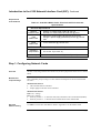
Step 1. Configuring Network Cards................................................................. 5-7
Overview......................................................................................................5-7
Motherboard Jumper Settings ....................................................................5-7
NIC Card Address Setting ..........................................................................5-7
NIC Card Jumper Settings.......................................................................... 5-8
Wired Media Card Jumper Settings............................................................ 5-8
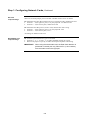
Step 2. Mounting Media Cards to the NIC....................................................... 5-9
Overview......................................................................................................5-9
Media Card Mounting ..................................................................................5-9
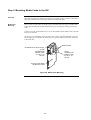
Step 3. Mounting Network Cards................................................................... 5-10
Step 4. Wiring Network Cards .......................................................................5-11
Overview....................................................................................................5-11
Wiring Guidelines....................................................................................... 5-11
Wiring Distances........................................................................................ 5-12
Related Documentation ............................................................................. 5-12
Fiber-Optic Wiring...................................................................................... 5-13
Fiber Optic Connection Types ...................................................................5-13
4190-9010 Coupler Requirements ............................................................5-14
Wiring with the Wired Media Card ............................................................. 5-15

ix
Wiring Illustrations .....................................................................................5-17
Wired Media, Style 7 Wiring .....................................................................5-17
Fiber Optic, Style 7 Wiring........................................................................ 5-18
Wired Media and Fiber Optic, Style 7 Wiring............................................5-19
Chapter 6 The System Power Supply & Alarm Relay Card..... 6-1
Introduction ..................................................................................................6-1
In this Chapter .............................................................................................6-1
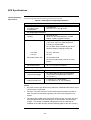
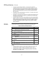
SPS Specifications .......................................................................................... 6-2
Input/Output/BatterySpecifications ..............................................................6-2
SPS Current Consumption ..........................................................................6-3
Environmental Requirements ...................................................................... 6-4
SPS Configuration ........................................................................................... 6-4
Overview......................................................................................................6-4
Jumper Settings........................................................................................... 6-4
Setting the Device Address .........................................................................6-4
Adjusting Voltages .......................................................................................6-4
SPS LED Indications ....................................................................................... 6-5
LEDs ............................................................................................................6-5
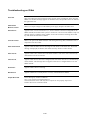
Troubleshooting on SPS.................................................................................. 6-6
Overview......................................................................................................6-6
IDNet Power Monitor Trouble ..................................................................... 6-6
Extra Device ................................................................................................6-6
Class A Trouble ........................................................................................... 6-6
Earth Fault Search....................................................................................... 6-6
Short Circuit ................................................................................................. 6-6
Channel Fail................................................................................................. 6-6
No Answer/ Bad Answer..............................................................................6-6
Output Abnormal.......................................................................................... 6-6
The Alarm Relay Card ..................................................................................... 6-7
Overview......................................................................................................6-7
Mounting ......................................................................................................6-7
Configuration ...............................................................................................6-8
Notes............................................................................................................ 6-8
Warning .......................................................................................................6-8
Specification ................................................................................................6-8
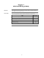
Chapter 7 SPS Field Wiring (4100U) ......................................... 7-1
Introduction ..................................................................................................7-1
In this Chapter .............................................................................................7-1
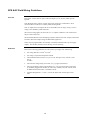
General Field Wiring Guidelines......................................................................7-2
General Guidelines ...................................................................................... 7-2
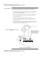
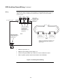
SPS NAC Field Wiring Guidelines...................................................................7-3
Overview......................................................................................................7-3
Guidelines.................................................................................................... 7-3
Class A NAC Wiring..................................................................................... 7-4
Class B NAC Wiring..................................................................................... 7-5
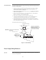
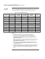
Power Supply Wiring Distances ......................................................................7-5
Overview......................................................................................................7-5
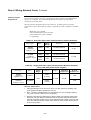
Class A NAC Wiring Table .........................................................................7-6
Class B NAC Wiring Table .........................................................................7-7

x
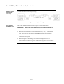
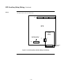
SPS Auxiliary Power Wiring ............................................................................7-8
Overview......................................................................................................7-8
Guidelines.................................................................................................... 7-8
Wiring...........................................................................................................7-9
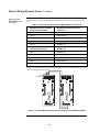
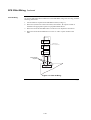
SPS Relay Wiring ..........................................................................................7-10
Overview....................................................................................................7-10
Aux 1 Relay ...............................................................................................7-10
Alarm Relay Card ......................................................................................7-10
Relays........................................................................................................7-11
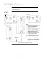
SPS IDNet Wiring ..........................................................................................7-12
Overview....................................................................................................7-12
IDNet Wiring ..............................................................................................7-12
Guidelines..................................................................................................7-12
Class A Wiring ........................................................................................... 7-13
Class B Wiring ........................................................................................... 7-14
Chapter 8 Installing 4100U IDNet & 4100MXP Cards ............... 8-1
Introduction ..................................................................................................8-1
In this Chapter .............................................................................................8-1
The IDNet Card................................................................................................8-2
Overview......................................................................................................8-2
LEDs ............................................................................................................8-3
Specifications............................................................................................... 8-3
Installing the IDNet Card onto the PDI ............................................................ 8-4
Overview......................................................................................................8-4
Installing the ID-Net into a 4100 Card Bay ...................................................... 8-5
Overview......................................................................................................8-5
Configuring the Card .......................................................................................8-6
Overview......................................................................................................8-6
Setting the Shield Tie Point ......................................................................... 8-6
Setting the Address .....................................................................................8-6
Wiring to IDNet Devices ..................................................................................8-7
Overview......................................................................................................8-7
Guidelines.................................................................................................... 8-7
Notes............................................................................................................ 8-8
Class A Wiring ............................................................................................. 8-8
Class B Wiring ............................................................................................. 8-9
Troubleshooting on IDNet..............................................................................8-10
Overview....................................................................................................8-10
IDNet Power Monitor Trouble ................................................................... 8-10
Extra Device ..............................................................................................8-10
Class A Trouble ......................................................................................... 8-10
Earth Fault Search.....................................................................................8-10
Short Circuit ...............................................................................................8-10
Channel Fail...............................................................................................8-10
No Answer ................................................................................................. 8-10
Bad Answer ...............................................................................................8-10
Output Abnormal........................................................................................ 8-10
The 4100MXP................................................................................................8-11
Introduction ................................................................................................8-11
Power Connection .....................................................................................8-11

xi
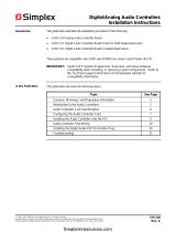
Chapter 9 PC Software Connections ........................................ 9-1
Introduction ..................................................................................................9-1
In this Chapter .............................................................................................9-1
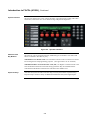
Software Modes............................................................................................... 9-2
Overview......................................................................................................9-2
Software Modes...........................................................................................9-2
Chapter 10 Australian Version Specifics................................ 10-1
Introduction ................................................................................................10-1
In this Chapter ...........................................................................................10-1
Summary Of Australian Version Specifics..................................................... 10-2
Overview....................................................................................................10-2
AS4428 Requirements...............................................................................10-2
Australian Panel Format ................................................................................ 10-3
Overview....................................................................................................10-3
Australian / USA Differences .....................................................................10-3
4100U/4100A Differences..........................................................................10-3
4100U Fan Control Module ...........................................................................10-4
Overview....................................................................................................10-4
Labeling ..................................................................................................... 10-4
Mounting & Connection ............................................................................. 10-4
Programming .............................................................................................10-4
Brigade Interfaces .........................................................................................10-6
Overview....................................................................................................10-6
Format........................................................................................................10-6
Applications ...............................................................................................10-6
Chapter 11 Installation Checklist, Commissioning
& Maintenance ............................................... 11-1
Introduction ................................................................................................11-1
In this Chapter ...........................................................................................11-1
Installation Checklist...................................................................................... 11-2
Overview....................................................................................................11-2
Alignment & Adjustment ................................................................................ 11-3
Overview....................................................................................................11-3
Power Up & Placing into Operation............................................................... 11-4
Maintenance ..................................................................................................11-5

xii
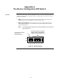
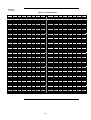
Appendix A The Device Configuration DIP Switch..................A-1
Overview......................................................................................................A-1
Appendix B Programming Requirements ................................B-1
Introduction ..................................................................................................B-1
In this Chapter .............................................................................................B-1
Required Features .......................................................................................B-1
Notes............................................................................................................B-1
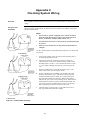
Appendix C Checking System Wiring.......................................C-1
Overview..................................................................................................... C-1
Using the Volt/ Ohm Meter ........................................................................ C-1
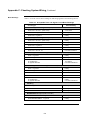
Meter Readings .......................................................................................... C-2
Appendix D Earth Fault Detection.............................................D-1
Overview..................................................................................................... D-1
General Guidelines......................................................................................... D-2
Earth Fault Searching from the Front Panel................................................... D-3
Overview..................................................................................................... D-3
Access Level Selection............................................................................... D-3
Starting the Earth Fault Search .................................................................. D-3
Search Option A: Select Location............................................................... D-4
Search Option B: Select Channel.............................................................. D-5
Search Option C: Last Search Result........................................................ D-5
Completing the Search ............................................................................... D-5
Search Results ............................................................................................... D-6
Overview..................................................................................................... D-6
Non-Point Faults ......................................................................................... D-6
Point Faults................................................................................................. D-6
Fault Not Found .......................................................................................... D-7
No Fault ...................................................................................................... D-7
Result Not Available ................................................................................... D-7
Earth Fault Search Example........................................................................... D-8
Appendix E Related Documentation.........................................E-1
Appendix F Compatible Actuating Devices .............................F-1
Introduction ..................................................................................................F-1
In this Chapter .............................................................................................F-1
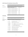
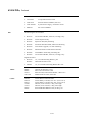
List of Approved Devices.................................................................................F-1
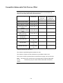
Compatible Detectors, IDNET .........................................................................F-4
Compatible Addressable Field Devices, IDNet ...............................................F-5

xiii
Appendix G Compatible Batteries............................................ G-1
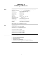
Appendix H 4100U Specifications.............................................H-1
General ....................................................................................................... H-1
Fuses .......................................................................................................... H-1
Firmware Features...................................................................................... H-1
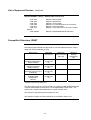
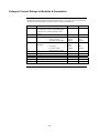
Voltage & Current Ratings of Modules & Assemblies .................................... H-2
Appendix I Power Supply & Battery Capacity Calculations ... I-1
Power Supply................................................................................................ I-1
Battery Capacity ...........................................................................................I-1
Appendix J Cable Characteristics............................................. J-1
IDNet............................................................................................................ J-1
4100 MAPNET II.......................................................................................... J-1
NETWORK .................................................................................................. J-1
Appendix K List of Drawings.....................................................K-1

xiv
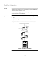
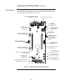
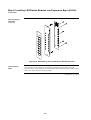
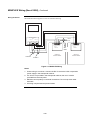
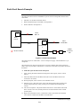
Figure 1-1. Standalone 4100U System ........................................................... 3
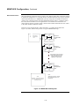
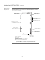
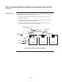
Figure 1-2. MINIPLEX 4100U System ............................................................ 5
Figure 1-3. Hub/Ring Configuration ................................................................ 6
Figure 1-4. Interconnected Loop Configuration............................................... 7
Figure 2-1. Master (CPU) Motherboard (566-227).......................................2-3
Figure 2-2. Master Controller Daughter Card (566-149).............................. 2-4
Figure 2-3. Operator Interface......................................................................2-6
Figure 2-4. System Power Supply................................................................ 2-7
Figure 2-5. The Power Distribution Interface (PDI)......................................2-8
Figure 2-6. Bracket Mounting ....................................................................... 2-9
Figure 2-7. Bay-to-Bay Interconnections.................................................... 2-13
Figure 2-8. Power and Communication Wiring for Motherboards..............2-14
Figure 2-9. Expansion Bay 4”x 5” Card Placement.................................... 2-15
Figure 2-10. Expansion Bay Motherboard Placement ................................. 2-16
Figure 2-11. Mixed Module Placement ........................................................2-17
Figure 2-12. Slave Card/PDI Connection.....................................................2-18
Figure 2-13. Installing the Motherboard in a 4100U Expansion Bay............2-19
Figure 2-14. LED/Switch Modules................................................................2-21
Figure 2-15. LED/Switch Controller..............................................................2-21
Figure 2-16. LED/Switch Card Mounting...................................................... 2-23
Figure 2-17. Controller Card Mounting.........................................................2-24
Figure 2-18. Assembling / Disassembling the LED Display Card ................ 2-25
Figure 2-19. LED/Switch Controller Wiring ..................................................2-26
Figure 2-20. Terminal Block Utility Module Mounting ..................................2-27
Figure 3-1. MINIPLEX System Design.......................................................3-31
Figure 3-2. The Remote Unit Interface Card..............................................3-32
Figure 3-3. The RIC II Card........................................................................ 3-33
Figure 3-4. Installing the RUI Motherboard in the CPU Bay ......................3-35
Figure 3-5. Installing the RIC II Motherboard into a 4100 Expansion Bay.3-36
Figure 3-6. Power and Communication Wiring for the Transponder
Cabinet (4100) .........................................................................3-38
Figure 3-7. MINIPLEX Wiring.....................................................................3-40
Figure 4-1. Transponder Interface Cards..................................................... 4-4
Figure 4-2. TIC Mounting .............................................................................4-9
Figure 4-3. Transponder Cabinet Interconnections....................................4-10
Figure 4-5. TIC Wiring to the Host Panel ................................................... 4-11
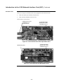
Figure 5-1. 4100-6014 Network Interface Card............................................ 5-4
Figure 5-2. UT Motherboard with City Connection (565-274) ......................5-5
Figure 5-3. UT Motherboard without City Connection (565-275)................. 5-5
Figure 5-4. The 4100/4120-0143 Fiber-Optic Media Card...........................5-6
Figure 5-5. The 4100/4120-0142 Wired Media Card ...................................5-6
Figure 5-6. Media Card Mounting ................................................................5-9
Figure 5-7. Installing the Daughter Card .................................................... 5-10
Figure 5-8. The Transient Suppressor .......................................................5-12
Figure 5-9. Fiber Wiring.............................................................................. 5-13
Figure 5-10. Coupler Wiring .........................................................................5-15
Figure 5-11. Wired Media Interconnections Between 4100U Motherboards5-16
Figure 5-12. Wired Media, Style 7 Wiring ....................................................5-17
Figure 5-13. Fiber Optic, Style 7 Wiring ....................................................... 5-18
Figure 5-14. Wired Media and Fiber Optic, Style 7 Wiring...........................5-19
Figure 6-1. The Alarm Relay Card ...............................................................6-7
Figure 7-1. The Ferrite Bead (SX0005)........................................................7-2
Figure 7-2. Class A NAC Wiring................................................................... 7-4
Figure 7-3. Class B Wiring ........................................................................... 7-5
Figure 7-4. Auxiliary Power Wiring............................................................... 7-9
Figure 7-5. Auxiliary Relay & Alarm Relay Card Relays ............................7-11
Figure 7-6. Class A Wiring .........................................................................7-13
Figure 7-7. Class B Wiring .........................................................................7-14
Figure 8-1. The IDNet Card..........................................................................8-2
List of Figures

xv
Figure 8-2. Mounting onto the Power Distribution Interface......................... 8-4
Figure 8-3. Mounting into 4100 (legacy) Bay ...............................................8-5
Figure 8-4. DIP Switch SW1......................................................................... 8-6
Figure 8-5. Class A Wiring ........................................................................... 8-8
Figure 8-6. Class B Wiring ........................................................................... 8-9
Figure 9-1. Service and Diagnostic Interface ...............................................9-2
Figure 9-2. Data Transfer Interface.............................................................. 9-2
Figure 9-3. Bootloader Interface ..................................................................9-3
Figure 10-1. Fan Control Module ................................................................. 10-5
Figure D-1. Volt/Ohm Meter Readings ........................................................D-1
Figure G-1. Earth Fault Search Example.....................................................G-8
Table 2-1 Master Controller LEDs 1 through 4 .............................................2-1
Table 5-1 4100 NIC & Media Cards – Electrical and Environmental
Specifications................................................................................ 5-7
Table 5-2 Wiring Distances.........................................................................5-12
Table 5-3 Dual Fiber Optic Cable Communications Distance Examples ...5-14
Table 5-4 Single Fiber Optic Cable Communications Distance
Examples using 4190-9010 Bi-Directional Couplers ..................5-14
Table 5-5 566-227 CPU Motherboard Wired Media Connections ..............5-16
Table 6-1 SPS Input and Output Specifications ........................................... 6-2
Table 6-2 SPS Current Specifications ..........................................................6-3
Table 6-3 Alarm Relay Card Jumper Positions............................................. 6-8
Table 7-1 Class A Wiring Distances .............................................................7-6
Table 7-2 Class B Wiring Distances .............................................................7-7
Table 8-1 IDNet Specifications .....................................................................8-3
Table 8-2 Cable Run Lengths .......................................................................8-8
Table 10-1 Switch/LED Format.....................................................................10-4
Table 10-2 Switch Status ..............................................................................10-4
Table A-1 Card Addresses ............................................................................A-2
Table C-1 Acceptable Zone and Signal Circuit Meter Readings.................. C-2
List of Tables

xvi

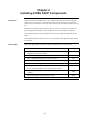
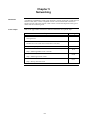
1-1
The 4100/4100U is an expandable fire alarm system that can be used as a standalone
system with one host panel, or as a wide-ranging system with several remote cabinets,
with or without multiple host panels. This chapter is an overview of standalone,
MINIPLEX, and network 4100 system concepts.
Refer to the page number listed in this table for information on a specific topic.
Topic See Page #
System Configurations
1-2
Standalone Configuration
1-3
MINIPLEX Configuration
1-4
Network Configuration
1-6
4100 PIDs (Non-4100U)
1-8
4100U Cabinet Part Identification Numbers (PIDs)
1-9
4100U PIDs
1-9
Chapter 1
Introduction to the 4100U Fire Alarm System
Introduction
In this Chapter

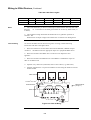
1-2
The 4100U is available as a standalone system with one host panel, or as an expansive
system with several remote back boxes, with or without multiple host panels. The type of
configuration used depends on the size of the site into which it is being installed.
The following types of configurations are offered:
Standalone. Comprised of one FACP and its assorted warning devices, initiating devices,
and signaling line circuit devices.
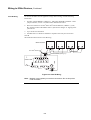
MINIPLEX. A standalone system plus remote transponder cabinets, which allow for
additional slave modules to be used. Typically used for multi-level buildings and small
multi-building applications.
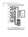
Network. A multi-FACP system connected by network cards. Each panel maintains the
status and control of its own circuit points while monitoring and controlling activity at
other locations. Network nodes may perform similar tasks, or may be dedicated to
specific functions.
This chapter outlines the fundamental concepts of each configuration.
System Configurations
Overview
Page is loading ...
Page is loading ...
Page is loading ...
Page is loading ...
Page is loading ...
Page is loading ...
Page is loading ...
Page is loading ...
Page is loading ...
Page is loading ...
Page is loading ...
Page is loading ...
Page is loading ...
Page is loading ...
Page is loading ...
Page is loading ...
Page is loading ...
Page is loading ...
Page is loading ...
Page is loading ...
Page is loading ...
Page is loading ...
Page is loading ...
Page is loading ...
Page is loading ...
Page is loading ...
Page is loading ...
Page is loading ...
Page is loading ...
Page is loading ...
Page is loading ...
Page is loading ...
Page is loading ...
Page is loading ...
Page is loading ...
Page is loading ...
Page is loading ...
Page is loading ...
Page is loading ...
Page is loading ...
Page is loading ...
Page is loading ...
Page is loading ...
Page is loading ...
Page is loading ...
Page is loading ...
Page is loading ...
Page is loading ...
Page is loading ...
Page is loading ...
Page is loading ...
Page is loading ...
Page is loading ...
Page is loading ...
Page is loading ...
Page is loading ...
Page is loading ...
Page is loading ...
Page is loading ...
Page is loading ...
Page is loading ...
Page is loading ...
Page is loading ...
Page is loading ...
Page is loading ...
Page is loading ...
Page is loading ...
Page is loading ...
Page is loading ...
Page is loading ...
Page is loading ...
Page is loading ...
Page is loading ...
Page is loading ...
Page is loading ...
Page is loading ...
Page is loading ...
Page is loading ...
Page is loading ...
Page is loading ...
Page is loading ...
Page is loading ...
Page is loading ...
Page is loading ...
Page is loading ...
Page is loading ...
Page is loading ...
Page is loading ...
Page is loading ...
Page is loading ...
Page is loading ...
Page is loading ...
Page is loading ...
Page is loading ...
Page is loading ...
Page is loading ...
Page is loading ...
Page is loading ...
Page is loading ...
Page is loading ...
Page is loading ...
Page is loading ...
Page is loading ...
Page is loading ...
Page is loading ...
Page is loading ...
Page is loading ...
Page is loading ...
Page is loading ...
Page is loading ...
Page is loading ...
Page is loading ...
Page is loading ...
Page is loading ...
Page is loading ...
Page is loading ...
Page is loading ...
Page is loading ...
Page is loading ...
Page is loading ...
Page is loading ...
Page is loading ...
Page is loading ...
Page is loading ...
Page is loading ...
Page is loading ...
Page is loading ...
Page is loading ...
Page is loading ...
Page is loading ...
Page is loading ...
Page is loading ...
Page is loading ...
Page is loading ...
Page is loading ...
Page is loading ...
Page is loading ...
Page is loading ...
Page is loading ...
Page is loading ...
Page is loading ...
Page is loading ...
Page is loading ...
Page is loading ...
Page is loading ...
Page is loading ...
Page is loading ...
Page is loading ...
Page is loading ...
Page is loading ...
Page is loading ...
Page is loading ...
Page is loading ...
Page is loading ...
Page is loading ...
Page is loading ...
Page is loading ...
Page is loading ...
Page is loading ...
Page is loading ...
-
 1
1
-
 2
2
-
 3
3
-
 4
4
-
 5
5
-
 6
6
-
 7
7
-
 8
8
-
 9
9
-
 10
10
-
 11
11
-
 12
12
-
 13
13
-
 14
14
-
 15
15
-
 16
16
-
 17
17
-
 18
18
-
 19
19
-
 20
20
-
 21
21
-
 22
22
-
 23
23
-
 24
24
-
 25
25
-
 26
26
-
 27
27
-
 28
28
-
 29
29
-
 30
30
-
 31
31
-
 32
32
-
 33
33
-
 34
34
-
 35
35
-
 36
36
-
 37
37
-
 38
38
-
 39
39
-
 40
40
-
 41
41
-
 42
42
-
 43
43
-
 44
44
-
 45
45
-
 46
46
-
 47
47
-
 48
48
-
 49
49
-
 50
50
-
 51
51
-
 52
52
-
 53
53
-
 54
54
-
 55
55
-
 56
56
-
 57
57
-
 58
58
-
 59
59
-
 60
60
-
 61
61
-
 62
62
-
 63
63
-
 64
64
-
 65
65
-
 66
66
-
 67
67
-
 68
68
-
 69
69
-
 70
70
-
 71
71
-
 72
72
-
 73
73
-
 74
74
-
 75
75
-
 76
76
-
 77
77
-
 78
78
-
 79
79
-
 80
80
-
 81
81
-
 82
82
-
 83
83
-
 84
84
-
 85
85
-
 86
86
-
 87
87
-
 88
88
-
 89
89
-
 90
90
-
 91
91
-
 92
92
-
 93
93
-
 94
94
-
 95
95
-
 96
96
-
 97
97
-
 98
98
-
 99
99
-
 100
100
-
 101
101
-
 102
102
-
 103
103
-
 104
104
-
 105
105
-
 106
106
-
 107
107
-
 108
108
-
 109
109
-
 110
110
-
 111
111
-
 112
112
-
 113
113
-
 114
114
-
 115
115
-
 116
116
-
 117
117
-
 118
118
-
 119
119
-
 120
120
-
 121
121
-
 122
122
-
 123
123
-
 124
124
-
 125
125
-
 126
126
-
 127
127
-
 128
128
-
 129
129
-
 130
130
-
 131
131
-
 132
132
-
 133
133
-
 134
134
-
 135
135
-
 136
136
-
 137
137
-
 138
138
-
 139
139
-
 140
140
-
 141
141
-
 142
142
-
 143
143
-
 144
144
-
 145
145
-
 146
146
-
 147
147
-
 148
148
-
 149
149
-
 150
150
-
 151
151
-
 152
152
-
 153
153
-
 154
154
-
 155
155
-
 156
156
-
 157
157
-
 158
158
-
 159
159
-
 160
160
-
 161
161
-
 162
162
-
 163
163
-
 164
164
-
 165
165
-
 166
166
-
 167
167
-
 168
168
-
 169
169
-
 170
170
-
 171
171
-
 172
172
-
 173
173
-
 174
174
-
 175
175
-
 176
176
-
 177
177
-
 178
178
-
 179
179
-
 180
180


Simplex 4100U User manual
- Category
- Fire protection
- Type
- User manual
- This manual is also suitable for
Ask a question and I''ll find the answer in the document
Finding information in a document is now easier with AI
Related papers
-
Tyco 4100U-S1 User manual
-
Simplex 4009 IDNet NAC Extender User manual
-
 Simplex 4100 Classic User manual
-
 Simplex 4090-9116 Installation Instructions Manual
-
 Simplex 0579159 Digital Analog Audio Controllers User manual
-
 Simplex MINIPLEX 4100-9600 User manual
-
 Simplex SafeLINC 4100 User manual
-
Simplex 4009-9809 User manual
-
 Simplex MINIPLEX 4100ES Series Installation guide
-
 Simplex MINIPLEX 4100ES Series Quick start guide


Other documents
-
Geovision GV-IO 12-Out Card V3 Installation guide
-
Manson ABD-4120 User manual
-
teko Astra-5 User manual
-
-
 Digital Monitoring Products X1 Series Output Expansion PCB Only Quick start guide
-
EMS Taktis Control Panel Installation guide
-
 Digital Monitoring Products X1 Series Output Expansion Module User guide
-
AMG AMG2747 and AMG2748 Installation guide
-
 Allstar Products Group Gate Operator Standby Power Supply User manual
-
 Allstar Products Group Gate Operator Standby Power Supply User manual


