Page is loading ...

Instructions-Parts
Heated Hoses and
Applicator Kits
For use with Graco
®
HFR
™
Metering Systems.
Not approved for use in European explosive atmospheres. For professional use only.
See page 2 for Maximum Fluid Working Pressures and approvals.
130 psi (0.9 MPa, 9 bar) Maximum Air Working Pressure
180°F (82°C) Maximum Hose Operating Temperature
Important Safety Instructions
Read all warnings and instructions in this manual.
Save these instructions.
3A0237L
EN

Related Manuals
2 3A0237L
Contents
Related Manuals . . . . . . . . . . . . . . . . . . . . . . . . . . . 2
Heated Hose Bundle Part Numbers . . . . . . . . . . . . 3
Fluid Temperature Sensor (FTS) . . . . . . . . . . . . . 4
Heated Whip Hose . . . . . . . . . . . . . . . . . . . . . . . 4
Individual Hoses . . . . . . . . . . . . . . . . . . . . . . . . . . . 5
Applicator Kits . . . . . . . . . . . . . . . . . . . . . . . . . . . . . 9
MD2 Valve Applicator Kits . . . . . . . . . . . . . . . . . 10
Warnings . . . . . . . . . . . . . . . . . . . . . . . . . . . . . . . . 11
Important Two-Component Material Information 14
Isocyanate Conditions . . . . . . . . . . . . . . . . . . . . 14
Material Self-ignition . . . . . . . . . . . . . . . . . . . . . 14
Keep Components A and B Separate . . . . . . . . 14
Moisture Sensitivity of Isocyanates . . . . . . . . . . 14
Foam Resins with 245 fa Blowing Agents . . . . . 14
Changing Materials . . . . . . . . . . . . . . . . . . . . . . 15
A and B Components . . . . . . . . . . . . . . . . . . . . . . 15
Installation . . . . . . . . . . . . . . . . . . . . . . . . . . . . . . . 16
Description . . . . . . . . . . . . . . . . . . . . . . . . . . . . 16
Connect Whip Hose to Gun or Gun Manifold . . 16
Connect Heated Hoses . . . . . . . . . . . . . . . . . . . 17
Connect FTS and Heated Whip Hose . . . . . . . . 20
Connect Solenoid Kit . . . . . . . . . . . . . . . . . . . . 21
Check Hoses for Leaks . . . . . . . . . . . . . . . . . . . 22
Protective Covering . . . . . . . . . . . . . . . . . . . . . . 22
Operation . . . . . . . . . . . . . . . . . . . . . . . . . . . . . . . . 23
Maintenance . . . . . . . . . . . . . . . . . . . . . . . . . . . . . . 24
Instructions for Replacing Individual A or B Hose 24
Clean Orifice . . . . . . . . . . . . . . . . . . . . . . . . . . . 24
Bundle Individual Whip Hoses . . . . . . . . . . . . . 26
Bundle Individual Heated Hoses . . . . . . . . . . . . 28
Parts . . . . . . . . . . . . . . . . . . . . . . . . . . . . . . . . . . . . 30
Whip Hoses . . . . . . . . . . . . . . . . . . . . . . . . . . . . 30
Heated Hose Bundles . . . . . . . . . . . . . . . . . . . . 32
Using Fluid Temperature Sensors For Single Heat
Zones . . . . . . . . . . . . . . . . . . . . . . . . . . . . . 35
Using Fluid Temperature Sensors for Dual Heat
Zones . . . . . . . . . . . . . . . . . . . . . . . . . . . . . 35
MD2 Applicator Kits . . . . . . . . . . . . . . . . . . . . . 37
Accessories . . . . . . . . . . . . . . . . . . . . . . . . . . . . . . 38
Scuff Guard . . . . . . . . . . . . . . . . . . . . . . . . . . . . 38
Solenoid Kits . . . . . . . . . . . . . . . . . . . . . . . . . . . 38
Technical Data . . . . . . . . . . . . . . . . . . . . . . . . . . . . 40
Graco Standard Warranty . . . . . . . . . . . . . . . . . . . 42
Graco Information . . . . . . . . . . . . . . . . . . . . . . . . 42
Related Manuals
Component Manuals in U.S. English:
Manual Description
313997 HFR Operation
313998 HFR, Repair-Parts
313872
EP
™
Gun, Instructions-Parts
312185 MD2 Valve, Instructions-Parts
312666
Fusion
™
CS Plural Component, Impinge-
ment Mix Spray Gun with ClearShot
™
Liq-
uid Technology, Instructions-Parts
310649
Fusion Automatic Plural Component,
Impingement Mix Spray Gun, Instruc-
tions-Parts
309550
Fusion Air Purge Plural Component,
Impingement Mix Spray Gun, Instruc-
tions-Parts
309856
Fusion Mechanical Purge Plural Compo-
nent, Impingement Mix Spray Gun,
Instructions-Parts
3A0861 Ratio Check Assembly, Instructions-Parts

Heated Hose Bundle Part Numbers
3A0237L 3
Heated Hose Bundle Part Numbers
Each hose contains an A component hose, a B component hose, and an air hose (1/4 npt x 1/4 npsm, m x f).
✿ If ordered as replacement hose for a HFR hose bun-
dles, reference manual 3A0237 not 309572.
★ All heated hose bundles are CE approved.
Part No. Ratio
ID
in. (mm)
Length
ft (m)
Single Hose Part No. JIC Fittings Maximum Fluid
Pressure
psi (MPa, bar)A (Red) B (Blue) A (Red) B (Blue)
Stainless Steel Dual Heat Zone Hose Bundle with Air Hose
24D108 2:1 1/4 (6) A x 3/8 (10) B 5 (1.5) 24E925 24E934 5/5 6/6 3500 (24, 241)
24D109 2:1 1/4 (6) A x 3/8 (10) B 10 (3) 24E927 24E936 5/5 6/6 3500 (24, 241)
24D110 2:1 1/4 (6) A x 3/8 (10) B 25 (7.6) 24E929 24E938 5/5 6/6 3500 (24, 241)
24D111 2:1 1/4 (6) A x 3/8 (10) B 50 (15.2) 24E931 24E940 5/5 6/6 3500 (24, 241)
24D112 1:1 3/8 (10) A x 3/8 (10) B 5 (1.5) 24E933 24E934 5/5 6/6 3500 (24, 241)
24D113 1:1 3/8 (10) A x 3/8 (10) B 10 (3) 24E935 24E936 5/5 6/6 3500 (24, 241)
24D114 1:1 3/8 (10) A x 3/8 (10) B 25 (7.6) 24E937 24E938 5/5 6/6 3500 (24, 241)
24D115 1:1 3/8 (10) A x 3/8 (10) B 50 (15.2) 24E939 24E940 5/5 6/6 3500 (24, 241)
Carbon Steel Dual Heat Zone Hose Bundle with Air Hose
24D116 2:1 1/4 (6) A x 3/8 (10)B 5 (1.5) 24E901 24E910 5/5 6/6 3500 (24, 241)
24D117 2:1 1/4 (6) A x 3/8 (10)B 10 (3) 24E903 24E912 5/5 6/6 3500 (24, 241)
24D118 2:1 1/4 (6) A x 3/8 (10)B 25 (7.6) 24E905 24E914 5/5 6/6 3500 (24, 241)
24D119 2:1 1/4 (6) A x 3/8 (10)B 50 (15.2) 24E907 24E916 5/5 6/6 3500 (24, 241)
24D120 1:1 3/8 (10) A x 3/8 (10) B 5 (1.5) 24E911 24E910 5/5 6/6 3500 (24, 241)
24D121 1:1 3/8 (10) A x 3/8 (10) B 10 (3) 24E913 24E912 5/5 6/6 3500 (24, 241)
24D122 1:1 3/8 (10) A x 3/8 (10) B 25 (7.6) 24E915 24E914 5/5 6/6 3500 (24, 241)
24D123 1:1 3/8 (10) A x 3/8 (10) B 50 (15.2) 24E917 24E916 5/5 6/6 3500 (24, 241)
Carbon Steel Single Heat Zone Hose Bundle with Air Hose
24D124 2:1 1/4 (6) A x 3/8 (10) B 25 (7.6) 261520 261523 5/5 6/6 2000 (14, 138)
24D125 2:1 1/4 (6) A x 3/8 (10) B 50 (15.2) 261514 261517 5/5 6/6 2000 (14, 138)
24D126 1:1 3/8 (10) A x 3/8 (10) B 25 (7.6) 261522 261523 5/5 6/6 2000 (14, 138)
24D127 1:1 3/8 (10) A x 3/8 (10) B 50 (15.2) 261516 261517 5/5 6/6 2000 (14, 138)
Carbon Steel Single Heat Zone Hose Bundle with Air Hose
24D129 2:1 1/4 (6) A x 3/8 B 50 (15.2) 261524 261527 5/5 6/6 3500 (24, 241)
24D131 1:1 3/8 (10) A x 3/8 (10) B 50 (15.2) 261526 261527 5/5 6/6 3500 (24, 241)
24E963 1:1 1/4 (6) A x 1/4 (6) B 25 (7.6) 246065✿ 246066✿ 5/5 6/6 2000 (14, 138)
24E964 1:1 1/4 (6) A x 1/4 (6) B 50 (15.2) 246059✿ 246060✿ 5/5 6/6 2000 (14, 138)
24E965 1:1 1/2 (13) A x 1/2 (13) B 50 (15.2) 246063✿ 246064✿ 5/5 6/6 2000 (14, 138)
24E966 1:1 1/4 (6) A x 1/4 (6) B 50 (15.2) 246067✿ 246068✿ 5/5 6/6 3500 (24, 241)
24E967 1:1 1/2 (13) A x 1/2 (13) B 50 (15.2) 246071✿ 246072✿ 5/5 6/6 3500 (24, 241)
24E968 1:1 1/4 (6) A x 1/4 (6) B 10 (3) 24D190 24D191 5/5 6/6 2000 (14, 138)
24E969 1:1 3/8 (10) A x 3/8 (10) B 10 (3) 24D760 24D761 5/5 6/6 2000 (14, 138)

Heated Hose Bundle Part Numbers
4 3A0237L
Fluid Temperature Sensor (FTS)
Heated Whip Hose
★ All heated whip hoses are CE approved.
Part No.
Fittings
Description
Maximum Fluid
Pressure
psi (MPa, bar)
258756 JIC to JIC Fluid Temperature Sensors for dual heat zones with stainless steel fittings 5000 (34.5, 345)
258758 JIC to JIC Fluid Temperature Sensors for single heat zone with stainless steel fittings 5000 (34.5, 345)
Part No.
ID
in. (mm)
Length
ft (m)
Single Hose Part No. JIC Fittings Maximum Fluid
Pressure
psi (MPa, bar)A (Red) B (Blue) A (Red) B (Blue)
Carbon Steel Single Heat Zone
24H076 1/4 (6) 10 (3) 24D190 24D191 5/5 6/6 3500 (24.1, 241)
24H077 3/8 (10) 10 (3) 24D760 24D760 5/5 6/6 3500 (24.1, 241)
Carbon Steel Dual Heat Zone
24H078 1/4 (6) 10 (3) 24H064 24H065 5/5 6/6 3500 (24.1, 241)
24H079 3/8 (10) 10 (3) 24H066 24H067 5/5 6/6 3500 (24.1, 241)
Stainless Steel Single Heat Zone
24H080 1/4 (6) 10 (3) 24H068 24H069 5/5 6/6 3500 (24.1, 241)
24H081 3/8 (10) 10 (3) 24H070 24H071 5/5 6/6 3500 (24.1, 241)
Stainless Steel Dual Heat Zone
24H082 1/4 (6) 10 (3) 24H072 24H073 5/5 6/6 3500 (24.1, 241)
24H083 3/8 (10) 10 (3) 24H074 24H075 5/5 6/6 3500 (24.1, 241)

Individual Hoses
3A0237L 5
Individual Hoses
A Side Heated Hoses (Red)
✿ If ordered as replacement hose for a HFR hose bun-
dles, reference manual 3A0237 not 309572.
★ All heated hoses are CE approved.
Part No.
ID
in. (mm)
Length
ft (m)
JIC
Fittings
Maximum
Fluid
Pressure
psi
(MPa, bar)
Carbon Steel Heated Dual Heat Zone
24E901 1/4 (6) 5 (1.5) 5/5 3500
(24, 241)
24E903 1/4 (6) 10 (3) 5/5 3500
(24, 241)
24E905 1/4 (6) 25 (7.6) 5/5 3500
(24, 241)
24E907 1/4 (6) 50 (15.2) 5/5 3500
(24, 241)
24E909 3/8 (10) 5 (1.5) 5/5 3500
(24, 241)
24E911 3/8 (10) 10 (3) 5/5 3500
(24, 241)
24E913 3/8 (10) 25 (7.6) 5/5 3500
(24, 241)
24E915 3/8 (10) 50 (15.2) 5/5 3500
(24, 241)
24E917 1/2 (13) 5 (1.5) 5/5 3500
(24, 241)
24E919 1/2 (13) 10 (3) 5/5 3500
(24, 241)
24E921 1/2 (13) 25 (7.6) 5/5 3500
(24, 241)
24E923 1/2 (13) 50 (15.2) 5/5 3500
(24, 241)
Carbon Steel Heated Single Heat Zone
246065✿ 1/4 (6) 25 (7.6) 5/5 2000
(14, 138)
246059✿ 1/4 (6) 50 (15.2) 5/5 2000
(14, 138)
246067✿ 1/4 (6) 50 (15.2) 5/5 3500
(24, 241)
246094✿ 3/8 (10) 25 (7.6) 5/5 2000
(14, 138)
246061✿ 3/8 (10) 50 (15.2) 5/5 2000
(14, 138)
246069✿ 3/8 (10) 50 (15.2) 5/5 3500
(24, 241)
246063✿ 1/2 (13) 50 (15.2) 8/8 2000
(14, 138)
246071✿ 1/2 (13) 50 (15.2) 8/8 3500
(24, 241)
24D190 1/4 (6) 10 (3) 5/5 2000
(14, 138)
24D760 3/8 (10) 10 (3) 5/5 2000
(14, 138)
Stainless Steel Heated Dual Heat Zone
24E925 1/4 (6) 5 (1.5) 5/5 3500
(24, 241)
24E927 1/4 (6) 10 (3) 5/5 3500
(24, 241)
24E929 1/4 (6) 25 (7.6) 5/5 3500
(24, 241)
24E931 1/4 (6) 50 (15.2) 5/5 3500
(24, 241)
24E933 3/8 (10) 5 (1.5) 5/5 3500
(24, 241)
24E935 3/8 (10) 10 (3) 5/5 3500
(24, 241)
24E937 3/8 (10) 25 (7.6) 5/5 3500
(24, 241)
24E939 3/8 (10) 50 (15.2) 5/5 3500
(24, 241)
24E941 1/2 (13) 5 (1.5) 5/5 3500
(24, 241)
24E943 1/2 (13) 10 (3) 5/5 3500
(24, 241)
24E945 1/2 (13) 25 (7.6) 5/5 3500
(24, 241)
24E947 1/2 (13) 50 (15.2) 5/5 3500
(24, 241)
Part No.
ID
in. (mm)
Length
ft (m)
JIC
Fittings
Maximum
Fluid
Pressure
psi
(MPa, bar)

Individual Hoses
6 3A0237L
A Side Unheated Hoses (Red)
Individual A Side Heated Whip Hose
Part No.
ID
in. (mm)
Length
ft (m)
JIC
Fittings
Maximum
Fluid
Pressure
psi (MPa, bar)
Carbon Steel Unheated
262173 1/4 (6) 5 (1.5) 5/5 3500
(24, 241)
262175 1/4 (6) 10 (3) 5/5 3500
(24, 241)
262177 1/4 (6) 25 (7.6) 5/5 3500
(24, 241)
262179 1/4 (6) 50 (15.2) 5/5 3500
(24, 241)
262181 3/8 (10) 5 (1.5) 5/5 3500
(24, 241)
262183 3/8 (10) 10 (3) 5/5 3500
(24, 241)
262185 3/8 (10) 25 (7.6) 5/5 3500
(24, 241)
262187 3/8 (10) 50 (15.2) 5/5 3500
(24, 241)
262189 1/2 (13) 5 (1.5) 8/8 3500
(24, 241)
262191 1/2 (13) 10 (3) 8/8 3500
(24, 241)
262193 1/2 (13) 25 (7.6) 8/8 3500
(24, 241)
262195 1/2 (13) 50 (15.2) 8/8 3500
(24, 241)
Stainless Steel Unheated
262236 1/4 (6) 5 (1.5) 5/5 3500
(24, 241)
262238 1/4 (6) 10 (3) 5/5 3500
(24, 241)
262240 1/4 (6) 25 (7.6) 5/5 3500
(24, 241)
262242 1/4 (6) 50 (15.2) 5/5 3500
(24, 241)
262244 3/8 (10) 5 (1.5) 5/5 3500
(24, 241)
262246 3/8 (10) 10 (3) 5/5 3500
(24, 241)
262248 3/8 (10) 25 (7.6) 5/5 3500
(24, 241)
262250 3/8 (10) 50 (15.2) 5/5 3500
(24, 241)
262252 1/2 (13) 5 (1.5) 8/8 3500
(24, 241)
262254 1/2 (13) 10 (3) 8/8 3500
(24, 241)
262256 1/2 (13) 25 (7.6) 8/8 3500
(24, 241)
262258 1/2 (13) 50 (15.2) 8/8 3500
(24, 241)
Part No.
ID
in. (mm)
Length
ft (m)
JIC
Fittings
Maximum
Fluid
Pressure
psi (MPa, bar)
Part No.
ID
in.
(mm)
Length
ft (m)
Heat
Zone
Maximum
Fluid
Pressure
psi (MPa, bar) Material
24E949 1/4 (6) 10 (3) Single 3500
(24, 241)
CST
24E951 3/8 (10) 10 (3) Single 3500
(24, 241)
CST
24H085 1/4 (6) 10 (3) Dual 3500
(24, 241)
CST
24H087 3/8 (10) 10 (3) Dual 3500
(24, 241)
CST
24H089 1/4 (6) 10 (3) Single 3500
(24, 241)
SST
24H091 3/8 (10) 10 (3) Single 3500
(24, 241)
SST
24H093 1/4 (6) 10 (3) Dual 3500
(24, 241)
SST
24H095 3/8 (10) 10 (3) Dual 3500
(24, 241)
SST
24H224 1/4 (6) 5 (1.5) Single 3500
(24, 241)
CST
24H226 3/8 (10) 5 (1.5) Single 3500
(24, 241)
CST
24H228 1/4 (6) 5 (1.5) Dual 3500
(24, 241)
CST
24H230 3/8 (10) 5 (1.5) Dual 3500
(24, 241)
CST
24H232 1/4 (6) 5 (1.5) Single 3500
(24, 241)
SST
24H234 3/8 (10) 5 (1.5) Single 3500
(24, 241)
SST
24H236 1/4 (6) 5 (1.5) Dual 3500
(24, 241)
SST
24H238 3/8 (10) 5 (1.5) Dual 3500
(24, 241)
SST
Part No.
ID
in.
(mm)
Length
ft (m)
Heat
Zone
Maximum
Fluid
Pressure
psi (MPa, bar) Material

Individual Hoses
3A0237L 7
B Side Heated Hoses (Blue)
✿ If ordered as replacement hose for a HFR hose bun-
dles, reference manual 3A0237 not 309572.
★ All heated hoses are CE approved.
Part No.
ID
in. (mm)
Length
ft (m)
JIC
Fittings
Maximum
Fluid
Pressure
psi (MPa, bar)
Carbon Steel Heated Dual Heat Zone
24E902 1/4 (6) 5 (1.5) 6/6 3500
(24, 241)
24E904 1/4 (6) 10 (3) 6/6 3500
(24, 241)
24E906 1/4 (6) 25 (7.6) 6/6 3500
(24, 241)
24E908 1/4 (6) 50 (15.2) 6/6 3500
(24, 241)
24E910 3/8 (10) 5 (1.5) 6/6 3500
(24, 241)
24E912 3/8 (10) 10 (3) 6/6 3500
(24, 241)
24E914 3/8 (10) 25 (7.6) 6/6 3500
(24, 241)
24E916 3/8 (10) 50 (15.2) 6/6 3500
(24, 241)
24E918 1/2 (13) 5 (1.5) 6/6 3500
(24, 241)
24E920 1/2 (13) 10 (3) 6/6 3500
(24, 241)
24E922 1/2 (13) 25 (7.6) 6/6 3500
(24, 241)
24E924 1/2 (13) 50 (15.2) 6/6 3500
(24, 241)
Carbon Steel Heated Single Heat Zone
246066✿ 1/4 (6) 25 (7.6) 6/6 2000
(14, 138)
246060✿ 1/4 (6) 50 (15.2) 6/6 2000
(14, 138)
246095✿ 3/8 (10) 25 (7.6) 6/6 2000
(14, 138)
246070✿ 3/8 (10) 50 (15.2) 6/6 2000
(14, 138)
246062✿ 3/8 (10) 50 (15.2) 6/6 2000
(14, 138)
246064✿ 1/2 (13) 50 (15.2) 6/6 2000
(14, 138)
246068✿ 1/4 (6) 50 (15.2) 6/6 3500
(24, 241)
246072✿ 1/2 (13) 50 (15.2) 6/6 3500
(24, 241)
24D191 1/4 (6) 10 (3) 6/6 2000
(14, 138)
24D761 3/8 (10) 10 (3) 6/6 2000
(14, 138)
Stainless Steel Heated Dual Heat Zone
24E926 1/4 (6) 5 (1.5) 6/6 3500
(24, 241)
24E928 1/4 (6) 10 (3) 6/6 3500
(24, 241)
24E930 1/4 (6) 25 (7.6) 6/6 3500
(24, 241)
24E932 1/4 (6) 50 (15.2) 6/6 3500
(24, 241)
24E934 3/8 (10) 5 (1.5) 6/6 3500
(24, 241)
24E936 3/8 (10) 10 (3) 6/6 3500
(24, 241)
24E938 3/8 (10) 25 (7.6) 6/6 3500
(24, 241)
24E940 3/8 (10) 50 (15.2) 6/6 3500
(24, 241)
24E942 1/2 (13) 5 (1.5) 6/6 3500
(24, 241)
24E944 1/2 (13) 10 (3) 6/6 3500
(24, 241)
24E946 1/2 (13) 25 (7.6) 6/6 3500
(24, 241)
24E948 1/2 (13) 50 (15.2) 6/6 3500
(24, 241)
Part No.
ID
in. (mm)
Length
ft (m)
JIC
Fittings
Maximum
Fluid
Pressure
psi (MPa, bar)

Individual Hoses
8 3A0237L
B Side Unheated Hoses (Blue)
Individual B Side Heated Whip Hose
Part No.
ID
in. (mm)
Length
ft (m)
JIC
Fittings
Maximum
Fluid
Pressure
psi (MPa, bar)
Carbon Steel Unheated
262174 1/4 (6) 5 (1.5) 6/6 3500
(24, 241)
262176 1/4 (6) 10 (3) 6/6 3500
(24, 241)
262178 1/4 (6) 25 (7.6) 6/6 3500
(24, 241)
262180 1/4 (6) 50 (15.2) 6/6 3500
(24, 241)
262182 3/8 (10) 5 (1.5) 6/6 3500
(24, 241)
262184 3/8 (10) 10 (3) 6/6 3500
(24, 241)
262186 3/8 (10) 25 (7.6) 6/6 3500
(24, 241)
262188 3/8 (10) 50 (15.2) 6/6 3500
(24, 241)
262190 1/2 (13) 5 (1.5) 10/10 3500
(24, 241)
262192 1/2 (13) 10 (3) 10/10 3500
(24, 241)
262194 1/2 (13) 25 (7.6) 10/10 3500
(24, 241)
262196 1/2 (13) 50 (15.2) 10/10 3500
(24, 241)
Stainless Steel Unheated
262237 1/4 (6) 5 (1.5) 6/6 3500
(24, 241)
262239 1/4 (6) 10 (3) 6/6 3500
(24, 241)
262241 1/4 (6) 25 (7.6) 6/6 3500
(24, 241)
262243 1/4 (6) 50 (15.2) 6/6 3500
(24, 241)
262245 3/8 (10) 5 (1.5) 6/6 3500
(24, 241)
262247 3/8 (10) 10 (3) 6/6 3500
(24, 241)
262249 3/8 (10) 25 (7.6) 6/6 3500
(24, 241)
262251 3/8 (10) 50 (15.2) 6/6 3500
(24, 241)
262253 1/2 (13) 5 (1.5) 10/10 3500
(24, 241)
262255 1/2 (13) 10 (3) 10/10 3500
(24, 241)
262257 1/2 (13) 25 (7.6) 10/10 3500
(24, 241)
262259 1/2 (13) 50 (15.2) 10/10 3500
(24, 241)
Part No.
ID
in. (mm)
Length
ft (m)
JIC
Fittings
Maximum
Fluid
Pressure
psi (MPa, bar)
Part No.
ID
in. (mm)
Length
ft (m)
Heat
Zone
Maximum
Fluid
Pressure
psi (MPa, bar) Material
24E950 1/4 (6) 10 (3) Single 3500
(24, 241)
CST
24E952 3/8 (10) 10 (3) Single 3500
(24, 241)
CST
24H086 1/4 (6) 10 (3) Dual 3500
(24, 241)
CST
24H088 3/8 (10) 10 (3) Dual 3500
(24, 241)
CST
24H090 1/4 (6) 10 (3) Single 3500
(24, 241)
SST
24H092 3/8 (10) 10 (3) Single 3500
(24, 241)
SST
24H094 1/4 (6) 10 (3) Dual 3500
(24, 241)
SST
24H096 3/8 (10) 10 (3) Dual 3500
(24, 241)
SST
24H225 1/4 (6) 5 (1.5) Single 3500
(24, 241)
CST
24H227 3/8 (10) 5 (1.5) Single 3500
(24, 241)
CST
24H229 1/4 (6) 5 (1.5) Dual 3500
(24, 241)
CST
24H231 3/8 (10) 5 (1.5) Dual 3500
(24, 241)
CST
24H233 1/4 (6) 5 (1.5) Single 3500
(24, 241)
SST
24H235 3/8 (10) 5 (1.5) Single 3500
(24, 241)
SST
24H237 1/4 (6) 5 (1.5) Dual 3500
(24, 241)
SST
24H239 3/8 (10) 5 (1.5) Dual 3500
(24, 241)
SST
Part No.
ID
in. (mm)
Length
ft (m)
Heat
Zone
Maximum
Fluid
Pressure
psi (MPa, bar) Material

Applicator Kits
3A0237L 9
Applicator Kits
The table below lists applicators that can be used with the heated hoses and identifies which applicators require sole-
noid kits. See Related Manuals for the applicator manual numbers.
NOTE: The MD2 valves must use one of the chemical connection kits to connect to the fluid hoses. See MD2
Valve Applicator Kits on page 10.
NOTE: When selecting an applicator, if an applicator is chosen which does not have a signal communicating to the
HFR, then the sizes of the A and B pumps added together must be greater or equal to 120 cc. For example: A (red)
pump size = 20 cc, B (blue) pump size = 100 cc, 20 cc + 100 cc = 120 cc. Since the pump sizes combined = 120 cc,
an applicator may be selected which does not have a signal communicating to the HFR.
Applicator Handle Options Required Solenoid Kit Pressure Relief Kit
Automatic Fusion Air Purge Guns No handle
24D161
Automatic Fusion Mechanical Purge Guns No handle
24D161
Fusion Air Purge Guns
24C067
Fusion Mechanical Purge Guns
24C067
Fusion CS Guns
24C067
EP Gun
No handle
Electric actuated pistol
1:1 and 10:1 MD2 Valves
(See MD2 Valve Applicator Kits on page 10
for models and chemical connection kits)
No handle
24D160, 24C757
Electric actuated pistol
24D160, 24C757
Pneumatic
Electric actuated lever
24D160, 24C757

Applicator Kits
10 3A0237L
MD2 Valve Applicator Kits
Part No.
(Series)
MD2 Valve
(see manual 312185)
MD2 Handle Chemical Connection Kit
Electric
(255208)
Lever
(255249)
Pneumatic
(255206)
Carbon Steel
(24D414)
Stainless Steel
(24D162)
24D500
255179
(1:1 with soft seats)
✔
24D501
✔ ✔
24D502
✔ ✔
24D503
✔
24D504
✔ ✔
24D505
✔ ✔
24D509
255180
(1:1 with hard seats)
✔
24D510
✔ ✔
24D511
✔ ✔
24D512
✔ ✔
24D513
✔
24D514
✔ ✔
24D515
✔ ✔
24D516
✔ ✔
24D521
255181
(10:1 with soft seats)
✔
24D522
✔ ✔
24D523
✔ ✔
24D524
✔
24D525
✔ ✔
24D526
✔ ✔
24D530
255182
(10:1 with hard seats)
✔
24D531
✔ ✔
24D532
✔ ✔
24D533
✔✔
24D534
✔
24D535
✔ ✔
24D536
✔ ✔
24D537
✔ ✔

Warnings
3A0237L 11
Warnings
The following warnings are for the setup, use, grounding, maintenance, and repair of this equipment. The exclama-
tion point symbol alerts you to a general warning and the hazard symbol refers to procedure-specific risk. Refer back
to these warnings. Additional, product-specific warnings may be found throughout the body of this manual where
applicable.
WARNING
ELECTRIC SHOCK HAZARD
The hoses must be grounded. Improper grounding, set-up or usage of the hoses can cause electric
shock.
• Turn off and disconnect power before disconnecting before installing or servicing hoses.
• Connect to grounded power source.
• All electrical wiring must be done by a qualified electrician and comply with all local codes and
regulations.
• Never cut or puncture a hose cover.
• Do not expose to rain. Store indoors.
SKIN INJECTION HAZARD
High-pressure fluid from hose leaks, or ruptured components will pierce skin. This may look like just a
cut, but it is a serious injury that can result in amputation. Get immediate surgical treatment.
• Inspect hose before each use for cuts, bulges, kinks or any other damage.
• Replace hoses proactively at regular intervals based on your operating conditions.
• Replace damaged hose immediately.
• Tighten all fluid connections before operating the equipment.
• Keep clear of leaks.
• Do not stop or deflect leaks with your hand, body, glove, or rag.
• Never exceed hose Maximum Pressure or Temperature ratings.
• Only use chemicals that are compatible with wetted parts. See Technical Data in this manual.
Read MSDSs and fluid and solvent manufacturer’s recommendations.
• Follow the Pressure Relief Procedure when you stop spraying and before cleaning, checking, or
servicing equipment.
THERMAL EXPANSION HAZARD
Fluids subjected to heat in confined spaces, including hoses, can create a rapid rise in pressure due to
the thermal expansion. Over-pressurization can result in equipment rupture and serious injury.
• Open a valve to relieve the fluid expansion during heating.
• Replace hoses proactively at regular intervals based on your operating conditions.
BURN HAZARD
Equipment surfaces and fluid that’s heated can become very hot during operation. To avoid severe
burns:
• Do not touch hot fluid or equipment.

Warnings
12 3A0237L
TOXIC FLUID OR FUMES HAZARD
Toxic fluids or fumes can cause serious injury or death if splashed in the eyes or on skin, inhaled, or
swallowed.
• Read MSDSs to know the specific hazards of the fluids you are using.
• Store hazardous fluid in approved containers, and dispose of it according to applicable guidelines.
• Always wear chemically impermeable gloves when spraying, dispensing, or cleaning equipment.
FIRE AND EXPLOSION HAZARD
Flammable fumes, such as solvent and paint fumes, in work area can ignite or explode. To help
prevent fire and explosion:
• Use equipment only in well ventilated area.
• Eliminate all ignition sources; such as pilot lights, cigarettes, portable electric lamps, and plastic
drop cloths (potential static arc).
• Keep work area free of debris, including solvent, rags and gasoline.
• Do not plug or unplug power cords, or turn power or light switches on or off when flammable fumes
are present.
• Ground all equipment in the work area. See Grounding instructions.
• Use only grounded hoses.
• Hold gun firmly to side of grounded pail when triggering into pail.
• If there is static sparking or you feel a shock, stop operation immediately. Do not use equipment
until you identify and correct the problem.
• Keep a working fire extinguisher in the work area.
EQUIPMENT MISUSE HAZARD
Misuse can cause death or serious injury.
• Do not operate the unit when fatigued or under the influence of drugs or alcohol.
• Do not exceed the maximum working pressure or temperature rating of the lowest rated system
component. See Technical Data in all equipment manuals.
• Use fluids and solvents that are compatible with equipment wetted parts. See Technical Data in all
equipment manuals. Read fluid and solvent manufacturer’s warnings. For complete information
about your material, request MSDS from distributor or retailer.
• Do not leave the work area while equipment is energized or under pressure. Turn off all equipment
and follow the Pressure Relief Procedure when equipment is not in use.
• Check equipment daily. Repair or replace worn or damaged parts immediately with genuine
manufacturer’s replacement parts only.
• Do not alter or modify equipment.
• Use equipment only for its intended purpose. Call your distributor for information.
• Route hoses and cables away from traffic areas, sharp edges, moving parts, and hot surfaces.
• Do not kink or over bend hoses or use hoses to pull equipment.
• Keep children and animals away from work area.
• Comply with all applicable safety regulations.
WARNING

Warnings
3A0237L 13
PERSONAL PROTECTIVE EQUIPMENT
You must wear appropriate protective equipment when operating, servicing, or when in the operating
area of the equipment to help protect you from serious injury, including eye injury, hearing loss, inhala-
tion of toxic fumes, and burns. This equipment includes but is not limited to:
• Protective eyewear, and hearing protection.
• Respirators, protective clothing, and gloves as recommended by the fluid and solvent manufacturer.
WARNING

Important Two-Component Material Information
14 3A0237L
Important Two-Component Material Information
Isocyanate Conditions
Material Self-ignition
Keep Components A and B
Separate
Moisture Sensitivity of
Isocyanates
Isocyanates (ISO) are catalysts used in two component
foam and polyurea coatings. ISO will react with moisture
(such as humidity) to form small, hard, abrasive crystals,
which become suspended in the fluid. Eventually a film
will form on the surface and the ISO will begin to gel,
increasing in viscosity. If used, this partially cured ISO
will reduce performance and the life of all wetted parts.
NOTE: NOTE: The amount of film formation and rate of
crystallization varies depending on the blend of ISO, the
humidity, and the temperature.
To prevent exposing ISO to moisture:
• Always use a sealed container with a desiccant
dryer in the vent, or a nitrogen atmosphere. Never
store ISO in an open container.
• Keep the ISO lube pump reservoir (if installed) filled
with Graco Throat Seal Liquid (TSL
™
), Part 206995.
The lubricant creates a barrier between the ISO and
the atmosphere.
• Use moisture-proof hoses specifically designed for
ISO, such as those supplied with your system.
• Never use reclaimed solvents, which may contain
moisture. Always keep solvent containers closed
when not in use.
• Never use solvent on one side if it has been contam-
inated from the other side.
• Always lubricate threaded parts with ISO pump oil
or grease when reassembling.
Foam Resins with 245 fa
Blowing Agents
Some foam blowing agents will froth at temperatures
above 90°F (33°C) when not under pressure, especially
if agitated. To reduce frothing, minimize preheating in a
circulation system.
Spraying or dispensing materials containing
isocyanates creates potentially harmful mists, vapors,
and atomized particulates.
Read material manufacturer’s warnings and material
MSDS to know specific hazards and precautions
related to isocyanates.
Prevent inhalation of isocyanate mists, vapors, and
atomized particulates by providing sufficient
ventilation in the work area. If sufficient ventilation is
not available, a supplied-air respirator is required for
everyone in the work area.
To prevent contact with isocyanates, appropriate
personal protective equipment, including chemically
impermeable gloves, boots, aprons, and goggles, is
also required for everyone in the work area.
Some materials may become self-igniting if applied
too thickly. Read material manufacturer’s warnings
and material MSDS.
Cross-contamination can result in cured material in
fluid lines which could cause serious injury or
damage equipment. To prevent cross-contamination
of the equipment’s wetted parts, never interchange
component A (isocyanate) and component B (resin)
parts.

A and B Components
3A0237L 15
Changing Materials
• When changing materials, flush the equipment mul-
tiple times to ensure it is thoroughly clean.
• Always clean the fluid inlet strainers after flushing.
• Check with your material manufacturer for chemical
compatibility.
• Most materials use ISO on the A side, but some use
ISO on the B side.
• Epoxies often have amines on the B (hardener)
side. Polyureas often have amines on the B (resin)
side.
A and B Components
IMPORTANT!
Material suppliers can vary in how they refer to plural
component materials.
Be aware that when standing in front of the manifold on
proportioner:
• Component A (Red) is on the left side.
• Component B (Blue) is on the right side.
For all machines:
• The A (Red) side is intended for ISO, hardeners,
and catalysts.
• If one of the materials being used is moisture-sensi-
tive, that material should always be in the A (Red)
side.
• The B (blue) side is intended for polyols, resins, and
bases.
NOTE: For ratios higher than 1:1, the higher volume
is typically the B (Blue) side.

Installation
16 3A0237L
Installation
Description
The heated hose maintains proper fluid temperature
while dispensing.
Fluid hoses are marked with red tape for ISO/hard-
ener/minor volume side, blue tape for RES/resin/major
volume side. Fittings have different sized threads to pre-
vent incorrect connection, which can cause fluid cross-
over and permanently damage the hose.
Hoses are 5 ft (1.5 m), 10 ft (3 m), 25 ft (7.6 m), and 50 ft
(15.2 m) long. The whip hose is 5 ft (1.5 m) or 10 ft (3 m)
long.
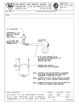
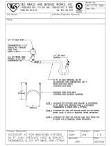
Connect Whip Hose to Gun or
Gun Manifold
NOTE: For best whip hose flexibility, assemble whip
hose to gun or gun manifold as instructed.
1. Assemble A and B component hoses to gun or gun
manifold fittings as shown in F
IG. 1 and FIG. 2.
2. If applicable, assemble signal cable (E1) and air
hose to gun or gun manifold fittings.
3. Tighten fittings to A and B component hoses.
Ensure hose remains flat after fittings are tightened.
Loosen and retighten fittings as necessary to elimi-
nate any torque on hoses. This will help achieve a
flat profile on the hose.
NOTE: Use chemical connection kit (153) on all MD2
valves. See F
IG. 2.
4. For MD2 valves with 255208 and 255249 and both
EP Gun models, connect the signal cable (E1) from
the applicator to the whip hose signal cable (3b).
5. See applicator manual for complete setup instruc-
tions.
F
IG. 1: Fusion Gun
F
IG. 2: MD2 Valve Kit 24D501
Tighten
Tighten
Tighten
r_24d501_3a0237_1a
153a
153b
A Side Hose
E1
3b
B Side Hose
153a
153c

Installation
3A0237L 17
Connect Heated Hoses
1. Lay heated hoses end to end, matching the color
coding. Red for component A (ISO), blue for compo-
nent B (RES).
2. Connect fluid hoses (A, B).
3. Connect signal cables (13).
NOTE: Do not connect the main air supply to the air
hose at this time.
4. Connect air hoses (C).
5. Connect electrical wires (D).
a. Ensure electrical wires ends are 5/8 in.
(0.625mm) long. If they are not, use a sharp
scissors to strip all four wire ends to the correct
length. See Strip Length Gauge for correct
length.
FIG. 3
F
IG. 4
A
B
TI14731a
TI14732a
B
A
13
FIG. 5
F
IG. 6
C
TI14733a
D
Single Heat Zone with A and B Heated Hose
Dual Heat Zone with A and B Heated Hose
TI15097a
C
D
D
Single Heat Zone with A or B Heated Hose
C
D
D
TI15140a
Strip Length
5/8 in.
TI9733a
(0.625 mm)
This illustration is not to scale.

Installation
18 3A0237L
NOTE: Be careful not to cut or nick copper strands.
If more than five strands are cut or nicked, trim wire
and re-strip.
New hoses are pre-stripped at correct length;
remove insulation to expose bare wire.
a. Ensure strip length is correct by fitting ferrule
over exposed wire. Ferrule should be flush with
wire end. See F
IG. 7.
NOTE: On some older heated hoses wire insulation
will not fit inside ferrule insulator. In these cases,
use scissors to split and remove ferrule insulator.
b. If wire is short of ferrule end, adjust strip length
accordingly. If bare wire is protruding from fer-
rule, trim flush to ferrule end. See F
IG. 7.
c. Remove ferrule and apply oxide inhibitor to bare
wire. See F
IG. 8.
d. Reinsert wire in ferrule and apply more oxide
inhibitor to ferrule and wire end.
6. Pair electrical wires as follows: A-Hose to A-Hose;
B-Hose to B-Hose.
NOTE: When connecting first hose section to pro-
portioner, wire pairing does not make a difference.
a. Insert one wire from heated hose into connec-
tor. Ensure that ferrule is mating with connector
insert. See F
IG. 9.
b. Thread in setscrew and use hex wrench to
torque setscrew to 60 in-lbs (6.78 N•m).
NOTE: To reach approximately 60 in-lbs (6.78 N•m),
complete 4.5 revolutions with hex wrench after set-
screw comes in contact with ferrule.
c. Insert remaining wire from pair into connector;
ensure proper insertion depth. Thread setscrew
and torque to 60 in-lbs (6.78 N•m); see sub-step
B. See F
IG. 9 and FIG. 10.
d. Repeat sub-steps A through C for remaining
wire pair.
e. Re-torque all setscrews to 60 in-lbs (6.78 N•m).
NOTE: When torqued to 60 in-lbs (6.78 N•m) set-
screws will be approximately flush with connector.
See F
IG. 11.
F
IG. 7
F
IG. 8
Incorrect
Correct
Incorrect
TI9768a
TI9769A
FIG. 9: Insert Wire and Setscrew
F
IG. 10: Torque Setscrew
TI9770A
TI9779A

Installation
3A0237L 19
f. Insert cap plugs over setscrews. See FIG. 11.
g. Wrap connector and wire on each side of con-
nector in black electrical tape to help seal out
moisture. Ensure 1 in. (25.4 mm) of wire on
each side of connector is wrapped.
7. Connect cables (F). Leave slack (G) in cables as
stress relief to prevent cable failure.
8. Repeat for additional hoses.
9. See Connect FTS and Heated Whip Hose, page
20.
F
IG. 11
F
IG. 12
Cap plugs
Setscrews
TI9771A
TI14734a
F
G

Installation
20 3A0237L
Connect FTS and Heated Whip Hose
1. For Single Zone Heat:
Carefully extend FTS probe (H) into the hose sec-
tion from the proportioner. Do not bend or kink
probe. Insert in component A (red) side of main
hose for foam or polyurea systems.
For Dual Zone Heat:
Carefully extend FTS probe (H) into the hose sec-
tions from the proportioner. Do not bend or kink
probe. Insert in component A (red) and component
B (blue) side of main hose for foam or polyurea sys-
tems.
2. Connect FTS (J) to whip hose (W).
3. Connect whip hose ground wire (K) to ground screw
on underside of FTS.
4. Connect fluid hoses to FTS (J).
NOTE: To use 1/2 in. (13 mm) ID fluid hoses, remove
the adapters from the proportioner fluid manifold
and install them in the FTS swivel inlets.
5. Connect electrical connectors (D).
6. Connect air hose (C) to whip air hose (L) or see
Connect Solenoid Kit on page 21 for installation
instructions.
7. Connect hose assembly cable (F) to FTS cable (R).
Leave slack (G) in cables as stress relief, to prevent
cable failure.
8. See Check Hoses for Leaks, page 22.
NOTICE
To prevent damage to probe, do not kink or exces-
sively bend hose. Do not coil hose tighter than the
minimum bend radius of 3 ft (0.9 m). Do not subject
hose to excessive weight, impact, or other abuse.
FIG. 13: FTS Connections
B
A
A
B
K
H
C
D
J
L
F
G
W
R
To Gun
To Proportioner
A
B
K
H
C
D
J
L
F
G
W
R
24D160 or 24D161, page 21
24D160 or 24D161, page 21
3b
24
To Gun
To Proportioner
Single Zone Heat
B
A
24
3b
D
ti14736b
ti14735a
D
D
Dual Zone Heat
/