HDBaseT hdm-944h100 Operating instructions
- Category
- Video switches
- Type
- Operating instructions
This manual is also suitable for
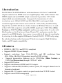
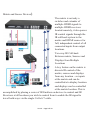
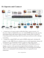
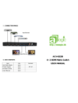
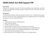
HDBaseT hdm-944h100 is a 4x4 HDMI matrix with simultaneous CAT5e/6/7 and HDMI outputs. It connects four HDMI sources to eight displays, supporting resolutions up to 1080p Full HD and 4Kx2K@30Hz. The device supports high-resolution digital audio formats such as LPCM 7.1CH, Dolby TrueHD, Dolby Digital Plus, and DTS-HD Master Audio. Connect a HD BaseT Receiver to extend the HDMI signal up to 328ft/100m (100m Version) or 230ft/70m(70m version) for multi-room connectivity. It works with Blu-Ray players, Set-Top boxes, Home Theater PCs, and game consoles that connect to an HDMI display.
HDBaseT hdm-944h100 is a 4x4 HDMI matrix with simultaneous CAT5e/6/7 and HDMI outputs. It connects four HDMI sources to eight displays, supporting resolutions up to 1080p Full HD and 4Kx2K@30Hz. The device supports high-resolution digital audio formats such as LPCM 7.1CH, Dolby TrueHD, Dolby Digital Plus, and DTS-HD Master Audio. Connect a HD BaseT Receiver to extend the HDMI signal up to 328ft/100m (100m Version) or 230ft/70m(70m version) for multi-room connectivity. It works with Blu-Ray players, Set-Top boxes, Home Theater PCs, and game consoles that connect to an HDMI display.


-
 1
1
-
 2
2
-
 3
3
-
 4
4
-
 5
5
-
 6
6
-
 7
7
-
 8
8
-
 9
9
-
 10
10
-
 11
11
-
 12
12
-
 13
13
-
 14
14
-
 15
15
-
 16
16
-
 17
17
-
 18
18
-
 19
19
-
 20
20


HDBaseT hdm-944h100 Operating instructions
- Category
- Video switches
- Type
- Operating instructions
- This manual is also suitable for
HDBaseT hdm-944h100 is a 4x4 HDMI matrix with simultaneous CAT5e/6/7 and HDMI outputs. It connects four HDMI sources to eight displays, supporting resolutions up to 1080p Full HD and 4Kx2K@30Hz. The device supports high-resolution digital audio formats such as LPCM 7.1CH, Dolby TrueHD, Dolby Digital Plus, and DTS-HD Master Audio. Connect a HD BaseT Receiver to extend the HDMI signal up to 328ft/100m (100m Version) or 230ft/70m(70m version) for multi-room connectivity. It works with Blu-Ray players, Set-Top boxes, Home Theater PCs, and game consoles that connect to an HDMI display.
Ask a question and I''ll find the answer in the document
Finding information in a document is now easier with AI
Other documents
-
 AMagic ACV-4323B User manual
-
Monoprice CDA-HD200EC User manual
-
VigilLink VLMX-862HT70 User manual
-
PTN HDBT44-N User manual
-
LC-Power LC-HDMI-3 Datasheet
-
Comprehensive CSW-HD440 User manual
-
-
ALFAtron MUH88E User manual
-
-
 LINK-MI LM-SW03-4K2K Owner's manual

