Page is loading ...

Assembly &
Owner’s Guide
ST710
MULTI-STATION GYM

2

3
ASSEMBLY GUIDE . . . . . . . . . . . . . . . . 4
HARDWARE BAGS . . . . . . . . . . . . . . . . 6
STEP 1: ORANGE BAG . . . . . . . . . . . . 11
STEP 2: BLUE BAG . . . . . . . . . . . . . . . 12
STEP 3: WEIGHT STACK . . . . . . . . . . . 13
STEP 4: PINK BAG . . . . . . . . . . . . . . . 14
STEP 5: GREEN BAG . . . . . . . . . . . . . . 15
STEP 6: BLACK BAG . . . . . . . . . . . . . . 16
STEP 7: CABLE #1 . . . . . . . . . . . . . . . 17
STEP 8: CABLE #2 . . . . . . . . . . . . . . . 18
STEP 9: CABLE #3 . . . . . . . . . . . . . . . 19
STEP 10: CABLE #4 . . . . . . . . . . . . . . 20
STEP 11: CABLE #5 . . . . . . . . . . . . . . 21
STEP 12: CABLE #6
(1/4” diameter) . . . 22
STEP 13: YELLOW BAG . . . . . . . . . . . 23
STEP 14: RED BAG . . . . . . . . . . . . . . 24
STEP 15: LIGHT BLUE BAG . . . . . . . . . 25
ASSEMBLY GUIDE OWNER’S GUIDE
EFFECTIVE RESISTANCE . . . . . . . . . . . 26
RESISTANCE TRAINING BENEFITS
& TIPS, WORKOUT VARIATIONS . . . . . . 28
TRAINING PROGRAMS . . . . . . . . . . . . 29
STRETCHING . . . . . . . . . . . . . . . . . . . 30
INCLUDED ACCESSORIES . . . . . . . . . . 32
PRESS ARM STATION EXERCISES . . . . 34
CENTER STATION EXERCISES . . . . . . . . 36
LEG PRESS/LAT PULLDOWN EXERCISES . 39
MAINTENANCE SCHEDULE . . . . . . . . . . 40
COMMERCIAL WARRANTY . . . . . . . . . . 41
WORKOUT LOGS . . . . . . . . . . . . . . . . 42
Table of Contents

4
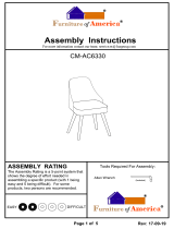
To avoid possible damage to this Multi-Station Gym, please follow these assembly steps in the correct order. Before
proceeding, find your new Multi-Station Gym serial number located on the side of the leg press floor support (AC3),
and enter here:
Refer to this number when calling for service, and enter this serial number on your Warranty Card and in your
own records. Be sure to read your Assembly/Owner’s Guide before using your new Multi-Station Gym.
If any parts, hardware or tools are missing, please call 1.800.335.4348, Extension 12.
NOTE: During assembly, it is recommended to ensure that all bolts are in place and partially threaded
before completely tightening any one bolt. During assembly steps 1 thru 6, do not completely tighten
any bolts until completion of Step 6. Also, it is recommended to apply grease to the fittings of the
pillow block bearings on the Leg Press station. This will ensure smooth operation and prevent rust.
Assembly &
Owner’s Guide
ST710
MULTI-STATION GYM

5
2
STEP
1
STEP
4
STEP
5
STEP
6
STEP
15
STEP
3
STEP
Serial #
14
STEP
13
STEP
Pinch Point
Decal
General
Warning
Decal

ORANGE BAG
6
BLUE BAG
HARDWARE INCLUDED
10.2 x 22 x 2
Flat Washer
Quantity: 12
M10 Nylon Nut
Quantity: 6
10.2 x 22 x 2
Flat Washer
Quantity: 18
M10 Nylon Nut
Quantity: 7
M10 x 78 Bolt
Quantity: 4
10.2 x 18.4 x 2.5
Lock Washer
Quantity: 5
M10 x 72 Bolt
Quantity: 1
M10 x 62 Bolt
Quantity: 6
M10 x 25 Bolt
Quantity: 1
M10 x 60 Bolt
Quantity: 2
12 x 26 x 2
Flat Washer
Quantity: 1
M6 x 8 Set Screw
Quantity: 4
M10 x 25 Bolt
Quantity: 4
M10 x 65 Bolt
Quantity: 2
5
3
/4” Shaft
(illustration not to scale)
Quantity: 1
8
7
/16” Axle
(illustration not to scale)
Quantity: 1

7
PINK BAG
GREEN BAG
HARDWARE INCLUDED
10.2 x 22 x 2
Flat Washer
Quantity: 10
M10 Nylon Nut
Quantity: 6
M10 x 62 Bolt
Quantity: 4
10.2 x 22 x 2
Flat Washer
Quantity: 26
M10 Nylon Nut
Quantity: 10
M10 x 62 Bolt
Quantity: 6
M10 x 67 Bolt
Quantity: 4
M10 x 25 Bolt
Quantity: 4
M10 x 100 Bolt
Quantity: 2
10.2 x 18.4 x 2.5
Lock Washer
Quantity: 6

8
BLACK BAG
HARDWARE INCLUDED
M10 Nylon Nut
Quantity: 8
12 x 26 x 2
Flat Washer
Quantity: 2
M10 x 62 Bolt
Quantity: 8
M12 x 25 Bolt
Quantity: 2
12.2 x 21 x 2.5
Lock Washer
Quantity: 2
10.2 x 22 x 2
Flat Washer
Quantity: 16
Pull Pin A
(illustration not to scale)
Quantity: 4
Pull Pin B
(illustration not to scale)
Quantity: 1
Axle
(illustration not to scale)
Quantity: 2
Sleeve
(illustration not to scale)
Quantity: 2

9
HARDWARE INCLUDED
YELLOW BAG
Accessory Storage Hook
(illustration not to scale)
Quantity: 3
Add-on Weight Storage Posts
(illustration not to scale)
Quantity: 2
M5 x 15 Bolt
Quantity: 6
10.2 x 22 x 2
Flat Washer
Quantity: 2
10.2 x 18.4 x 2.5
Lock Washer
Quantity: 2
M5 x 15 Screw
Quantity: 8
M8 x 20 Bolt
Quantity: 7
Attachment Clips Z30
(illustration not to scale)
Quantity: 4
Slip on nuts Z31
(illustration not to scale)
Quantity: 8
M10 x 25 Bolt
Quantity: 2

RED BAG
Pull Pin B
(illustration not to scale)
Quantity: 1
10
HARDWARE INCLUDED
LIGHT BLUE BAG
10.2 x 22 x 2
Flat Washer
Quantity: 9
M10 Nylon Nut
Quantity: 6
M10 x 68 Bolt
Quantity: 2
M10 x 125 Bolt
Quantity: 1
M10 x 25 Bolt
Quantity: 3
Small Disc (hole size)
(illustration not to scale)
Quantity: 6
Large Disc (hole size)
(illustration not to scale)
Quantity: 4
M8 x 20 Bolt
Quantity: 6
M10 x 25 Bolt
Quantity: 16
M6 x 8 Set Screw
Quantity: 1
8.4 x 15 x 1.6
Flat Washer
Quantity: 6
4” Axle
(illustration not to scale)
Quantity: 1

11
AK3
AC1
AC2
AC3
AK3
AB1
AC5
Inside
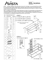
1
STEP
NOTE: Leave all hardware partially
loose, until the end of Step 6.
• Attach the press arm foot (AC5) to the
press arm floor support (AC1) using two
bolts (M10x65), two flat washers
(10.2x22x2), and two nylon nuts (M10).
• Stand up the main center upright (AB1)
and place the functional arm floor support
(AC2) up against the center holes at the
bottom of the main center upright.
Connect the two frame pieces with two
bolts (M10x60), and two flat washers
(10.2x22x2).
• Align the holes in one of the weight
stack support blocks (AK3) with the holes
on the bottom right side of the main center
upright (AB1). See diagram for orientation
of the block. Place the press arm floor
support (AC1) up against the weight stack
support block, aligning those holes. Slide
two bolts (M10x78) with flat washers
(10.2x22x2) through the holes, securing
them with two more flat washers and two
nylon nuts (M10). Repeat this process on
the remaining holes on the bottom of the
main center upright, using the leg press
floor support (AC3) and the other weight
stack support block.
ORANGE BAG

12
2
STEP
BLUE BAG
AC1
AC6
AH2
AN1
C33
AC4
AC3
AN2
• Place the center connecting support
(AC6) in between the functional arm floor
support and the leg press arm floor
support, aligning the holes. Slide two bolts
(M10x62) with flat washers (10.2x22x2)
through the holes into the functional arm
floor support. Secure bolts with two more
flat washers and two nylon nuts (M10).
Repeat on other side of connecting support.
• Attach two pillow block bearings (C33)
to the leg press foot (AC4) with four
bolts (M10x25), four lock washers
(10.2x18.4x2.5), and four flat washers
(10.2x22x2). Make sure the grease fittings
are positioned on the inside, pointing
towards the main center upright. Tighten.
• Take the leg press foot (AC4) and place
over the end of the leg press floor support
(AC3), aligning the holes. Slide two bolts
(M10x62) with flat washers (10.2x22x2)
through the holes, securing with two more
flat washers and two nylon nuts (M10).
• Loosely thread four set screws (M6x8) in
the axle housing on the leg press swing
arm (AN1). Place the axle (8
7
/16”) housing
of the leg press swing arm between the
pillow block bearings on the leg press
foot, making sure the pulley bracket is facing
the floor support. Slide the axle through
the holes and center it in the bearings.
Secure by tightening set screws.
• Attach the foot plate (AN2) to the leg
press swing arm (AN1) by sliding the shaft
(5.75”) through holes in foot plate and
swing arm, and securing with a flat washer
(12.2x26x2), lock washer (10.2x18.4x2.5)
and a bolt (M10x25).
• Attach the leg curl post (AH2) in
between the bracket on the press arm floor
support (AC1) using one bolt (M10x72),
two flat washers (10.2x22x2), and a
nylon nut (M10).

13
3
STEP
• Place weight stack bumpers (Q05) over
the holes of both weight stack support
blocks (AK3). Place the guide rods over
and through the rubber weight plate
bumpers into the weight stack support
block. Use caution when adding the
weight plates. Don’t let the guides tilt too
far forward during installation. Slide each
of the 20 weight plates over both sets of
the guide rods on top of one another.
Place the header weight plate over both
sets of guide rods on top of other weight
plates.
NOTE: Place the header plate
with the pulley bracket on the leg
press side weight stack! The header
plate without the pulley bracket will
go on press arm side.
• Slide a stopper ring (K18) on the left
guide rod of the leg press side and tighten
the set screw so the bottom edge of the
ring is nine inches from the top of the rod.
• Rest each guide rod behind the top
bracket on the main center upright (AB1).
WEIGHT STACK
Q05
Q05
AK3
AB1
AK3
K18

14
AC1
AC2
AB2
AC3
AH3
AB4
4
STEP
• With angled end down and pulley
brackets facing weight stack, place the
press arm upright (AB2) over the press arm
floor support (AC1), aligning the holes in
both components. Slide two bolts
(M10x62) with flat washers (10.2x22x2)
through holes and secure each of the bolts
with another flat washer and two nylon
nuts (M10).
• Take the adjustable handle assembly
and slide onto the functional arm upright
(AH3), making sure the handle is on the
side with the numbers. You will need to
squeeze the handle to slide over the
adjustment holes in the upright. Place the
functional arm upright (AH3), numbers
facing press arm upright (AB2), over the
exposed bolt ends on the functional arm
floor support (AC2). Secure the connection
with a flat washer (10.2x22x2) and a
nylon nut (M10) over each bolt end.
• With the hole for the cable on the bottom,
place the leg press upright (AB4) over the
leg press floor support (AC3). The upright
should angle upwards towards the weight
stacks. Align the holes in the upright with
the center holes in the floor support. Slide
two bolts (M10x62) with flat washers
(10.2x22x2) through the connection.
Secure each of the bolts with another flat
washer and a nylon nut (M10).
PINK BAG

15
AB2
AB3
AK2
AB1
AB5
AE3
AH3
AK2
AG1
Press Arm Leg Press
Inside
5
STEP
• Slide a weight stack upper block (AK2)
onto the guide rods of the press arm
weight stack. See diagram for orientation.
Take the press arm overhead tube (AB3)
and place in the bracket on top of the
press arm upright (AB2). Align the holes of
the overhead tube, weight stack upper
block, and main center upright (AB1).
Slide a bolt (M10x67) with a flat washer
(10.2x22x2) through each hole and
secure the bolts with another flat washer
and a nylon nut (M10). To secure the con-
nection between the press arm upright and
overhead tube, use two bolts (M10x62),
four flat washers (10.2x22x2), and two
nylon nuts (M10). Repeat this process on
leg press side with the leg press overhead
tube (AB5) and the other weight stack
upper block (AK2).
• Place the functional arm overhead tube
(AG1) over the main center upright (AB1)
and functional arm upright (AH3). Secure
the overhead tube to the main center
upright using four bolts (M10x25) with
four lock washers (10.2x18.4x2.5) and
four flat washers (10.2x22x2). To secure
the connection between overhead tube
and functional arm upright, use two
bolts (M10x100), two lock washers
(10.2x18.4x2.5), and two flat washers
(10.2x22x2).
• Attach the dual snap hook bar mount (AE3)
to AB5 with two bolts (M10x62), four flat
washers (10.2x22x2), and two nuts (M10).
Make sure snap hooks are on the bottom.
GREEN BAG

16
AD1
AD2
AB3
AJ1
AC1
AC3
AJ6
AB5
AT1
AB4
6
STEP
• Attach the press arm swing arm (AD2) to
the press arm overhead tube (AB3) using
one of the axles provided. Center the shaft
in the connection and secure with a sleeve
(lining the flat surface up with the flat inside
of swing arm), a bolt (M12x25), a flat
washer (12x26x2), and a lock washer
(12.2x21x2.5). See diagram for clarification.
• Using the same method as the previous
step, secure the press arm (AD1) to the press
arm swing arm (AD2) using remaining axle
provided. The handles on the press arm
should be angled away from the weight
stack. Thread a pull pin (B) into the swing
arm until secured in one of the range of
motion holes in press arm.
• Attach the press arm seat back post bracket
(AJ1) to the press arm upright using two bolts
(M10x62), four flat washers (10.2x22x2),
and two nylon nuts (M10). Thread pull pin
(A) into bracket. Repeat this process for the
leg press seat back post bracket (AJ6) on leg
press upright(AB4).
• Attach the leg press seat bottom support
(AT1) to the leg press floor support (AC3)
and leg press upright (AB4). Use four bolts
(M10x62), eight flat washers (10.2x22x2),
and four nylon nuts (M10) to secure both
connection points.
• Thread two pull pins (A) into the press arm
floor support (AC1).
•
Tighten all hardware.
BLACK BAG

17
A
B
C
D
E
F
G
H
7
STEP
Thread the bolt on the end of the cable (the
end with the permanent bolt affixed) to the
header plate a minimum of 1”, after slipping
the closed loop of the weight selector pin
tether over the attached nuts. Remove the
slotted bolt and nut from the opposite end of
the cable. Route the cable through the
following pulleys in the order specified:
Over pulley A, under B, over C, over D,
over E, over F, under G, and thread a minimum
of 0.5” into floating pulley housing H (after
reattaching the slotted bolt and nut). Tighten
the nut against the pulley housing.
WARNING: Failure to thread the ends in
the specified distance can result in
serious injury!
CABLE #1

18
I
J
K
L
Rubber
Spacers
H
M
8
STEP
NOTE: You will need to remove pulleys
H, I, J, K, L, and M to route cable #2.
• Route the loop only end of the cable
through the following pulleys in the specified
order: over pulley I, over J, under floating
pulley housing H, over K, under L, and
under M. Center the cable end loop
between the attachment points on the leg
curl post (AH2). Slide the shoulder bolt
(M8x16) through one side of the attachment
point, a rubber spacer, the cable eyelet, a
rubber spacer, and the other attachment
point. Attach a nut (M8). Tighten this and all
pulley bolts.
CABLE #2

O
N
P
Q
R
S
T
U
Front
Back
19
9
STEP
Remove the slotted bolt and nut from the end
of the cable. Route this end through the pulleys
in the specified order: thru the center of pulleys
N & O (dual transition pulley assembly),
under P, under Q, over the front of R, under
the back of S (top half of dual floating pulley
assembly), over the back of T, and over the
back of U. Reattach the slotted bolt and nut
to the end of the cable. Thread into the
receiving post of the dual transition pulley
assembly a minimum of 0.5”.
WARNING:
failure to thread the end in the specified
distance can result in serious injury!
CABLE #3

V
AB1
AB5
W
X
Z
AA
Y
20
10
STEP
Remove the slotted bolt and nut from one
end. Thread the opposite end, slotted bolt
into the attachment point at the bottom of the
main center upright (AB1) a minimum of 0.5”.
Tighten the nut against the attachment point.
Route the other end through the following
pulleys in the order specified: over the front
of pulley V, under the back of W, over the
back of X, under the back of Y, over the
back of Z, and under the back of floating
pulley AA. Reattach the slotted bolt and nut.
Thread a minimum of 0.5” into the attachment
point on the leg press overhead tube (AB5).
Tighten the nut against the tube.
WARNING:
Failure to thread the ends in the specified
distance can result in serious injury!
CABLE #4
/