
WARNING - RISK OF ELECTRIC SHOCK. DISCONNECT
MAIN POWER AT FUSE OR CIRCUIT BREAKER
BEFORE INSTALLING OR SERVICING THE FIXTURE.
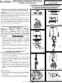
LED 4” RETROFIT TRIM INSTALLATION
INSTRUCTIONS - MODEL EVL4732DSWHxx
QUESTIONS? CALL TOLL
FREE 1-800-345-0542
Please read carefully and save these
instructions as you may need them at a later
date.
GENERAL: All electrical connections must be in accordance
with local and National Electrical Code (N.E.C.) standards. If
you are unfamiliar with proper electrical wiring connections
obtain the services of a qualified electrician.
Remove the trim from the box and make sure that no parts are
missing by referencing the PARTS illustrations.
THIS RETROFIT ASSEMBLY IS ACCEPTED AS A
COMPONENT OF A LED LUMINAIRE WHERE THE
SUITABILITY OF THE COMBINATION SHALL BE
DETERMINED BY CSA OR CANADIAN AUTHORITIES
HAVING JURISDICTION.
_________________________________________________
WARNING- RISK OF FIRE OR ELECTRIC
SHOCK
FOR USE WITH INCANDESCENT HOUSING MODELS:
COMMERCIAL ELECTRIC HBR2000B, HBR2000R,
HBR2000BICAT; HALO H99T, H99RT, H99ICT, H99TAT,
H99RTAT, H99ICAT; CORDELIA X2000LICAT, X2000LRICAT,
X2000LICATB; CAPRI R4, RR4; ELCO EL99A, EL99RA,
EL99ICA; JUNO TC1, TC1R; LITHONIA L3, L3R; PROGRESS
P832-TG, P830-TG; THOMAS PS4, PS4-RM; NORA NSCIC-
40IAT; ELITE B4, 4R. HALO LED HOUSINGS – H995ICAT,
H995RICAT.
• Do not alter, relocate, or remove wiring, lampholders, power
supply, or any other electrical component. Installation of
the retrofit assembly requires a person familiar with the
construction and operation of the luminaire’s electrical
system and the hazard involved. If not qualified, do not
attempt installation. Contact a qualified electrician.
• Do not make or alter any open holes in an enclosure of
wiring or electrical components during kit installation.
• To prevent wiring damage or abrasion, do not expose
wiring to edges of sheet metal or other sharp objects.
____________________________
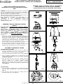
ASSEMBLY AND INSTALLATION
INCANDESCENT HOUSINGS
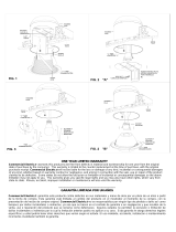
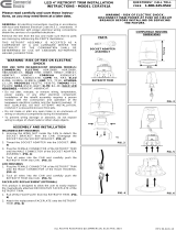
1. Unscrew the WING NUT inside the CAN to detach the
SOCKET BRACKET from the CAN. Disengage the
SOCKET from the SOCKET BRACKET. (FIG. 1)
2. Thread the SOCKET ADAPTER into the SOCKET. (FIG. 2)
3. Plug the FEMALE CONNECTOR of the RETROFIT TRIM
onto the MALE CONNECTOR of the SOCKET ADAPTER
ASSEMBLY. (FIG. 3)
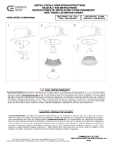
4. Tuck all wires into the CAN and carefully push the
RETROFIT TRIM into CAN. (NOTE: To provide enough
room in shallow cans, carefully position SOCKET
ADAPTER and SOCKET adjacent to the side of the LED
DRIVER prior to inserting the RETROFIT TRIM into the
CAN.) (FIG. 4)
LED HOUSINGS
1. Plug the FEMALE CONNECTOR of the RETROFIT TRIM
onto the MALE CONNECTOR of the HALO HOUSING.
(FIG. 3)
2. Tuck all wires into the CAN and carefully push the
RETROFIT TRIM into CAN. (FIG. 4)
5 ½ in.
4 in.
PARTS
SOCKET ADAPTER
ASSEMBLY
COMPATIBLE HOUSING
DIMENSIONS
RETROFIT TRIM
FIG. 1
FIG. 3
FIG. 2
FIG. 4
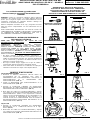
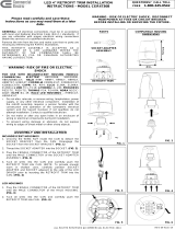
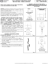
FIG. 6
ALL RIGHTS RESERVED ENVIROLITE 2014
FIG. 5
Driver Screws

ALL RIGHTS RESERVED ENVIROLITE 2014
_____________________________
FIVE-YEAR LIMITED WARRANTY
EnviroLite
warrants this product to be free from defects
in material and workmanship for five years from the original
date of purchase by the consumer. This warranty is limited
to the counter replacement at the time of purchase, with
the original purchase receipt. EnviroLite
will not be liable
for the loss or damage of any kind, incidental or
consequential damages of any kind, whether based on
warranty contract or negligence, and arising in connection
with the sale, use or repair of the product claimed to be
defective. Some states do not allow the exclusion or
limitation of incidental or consequential damages so the
above limitation may not apply to you. This warranty gives
you specific legal rights and you may also have other rights,
which vary from state to state. Misuse, accident, improper
installation or maintenance will also void the warranty.
_____________________________
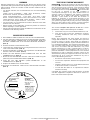
This device complies with part 15 of the FCC Rules.
Operation is subject to the following two conditions:
1. This device may not cause harmful interference, and
2. This device must accept any interference received,
including interference that may cause undesired
operation.
NOTE: This equipment has been tested and found to
comply with the limits for a Class B digital device, pursuant
to Part 15 of the FCC Rules. These limits are designed to
provide reasonable protection against harmful interference
in a residential installation. This equipment generates, uses
and can radiate radio frequency energy and, if not installed
and used in accordance with the instructions, may cause
harmful interference to radio communications. However,
there is no guarantee that interference will not occur in a
particular installation. If this equipment does cause harmful
interference to radio or television reception, which can be
determined by turning the equipment off and on, the user is
encouraged to try to correct the interference by one or
more of the following measures:
• Reorient or relocate the receiver antenna.
• Increase the separation between the equipment and
receiver.
• Install the product onto on a circuit different from that
to which the receiver is connected.
• Consult with the dealer or an experienced radio/TV
technician for help.
CAUTION: Any changes made to the electronics circuit will
void this equipment’s compliance with Part 15 of the FCC
Rules and should not be operated.
________
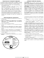
DIMMING
Dimming performance may depend on the dimmer, the dimmer range
adjustment setting (for dimmers with brightness range adjustments), the
wiring method, and/or the number of LED modules installed onto the
dimmer circuit.
• For dimmer selection, it is recommended to use one of the following
dimmers:
Leviton Decora SureSlide® – 6631, 6674 (Universal); Leviton
IllumaTech® - IPI06-1L, IPL06-10 (Universal)
Lutron Ariandni®/Toggler® - TGCL-153P, AYCL-153P; Lutron
Diva® - DVWCL-153P, DVCL-153P; Lutron Luméa® - LGCL-153P,
Lutron Maestro® - MACL-153M; Lutron Skylark® - S-600, S-603P,
SCL-153P; Lutron Skylark Contour™ - CTCL-153P.
• For best results, it is recommended to install a minimum of four LED
modules onto one dimmer.
• Before turning on the LED lights, set dimmer position at maximum
before adjusting to a lower light level.
• Please follow the dimming control manufacturer’s instructions for the
installation of all dimming controls.
_____________________
DRIVER REPLACEMENT
1. DISCONNECT MAIN POWER AT FUSE OR CIRCUIT BREAKER.
2. Pull the RETROFIT TRIM down from the RECESSED HOUSING.
Unplug the FEMALE CONNECTOR of the RETROFIT TRIM from
the MALE CONNECTOR of the SOCKET ADAPTER ASSEMBLY.
(FIG. 3)
3. Remove the LENS and the REFLECTOR.
4. Loosen the SET SCREW that is securing the black wire on the back
of the CAST HEAT SINK. (FIG. 5)
5. Remove the DRIVER SCREWS and separate the old LED DRIVER
from the CAST HEAT SINK. (FIG. 5)
6. Detach the LED DRIVER QUICK-CONNECTOR from the LED
TERMINAL BLOCK. (FIG. 6)
7. Mount the new LED DRIVER onto the CAST HEAT SINK using the
previously removed DRIVER SCREWS. (FIG. 5)
8. Insert the new LED DRIVER QUICK-CONNECTOR to the
TERMINAL BLOCK. (FIG. 6)
9. Replace the REFLECTOR and the LENS.
10.Re-install the RETROFIT TRIM into the RECESSED HOUSING.
(FIG. 4)
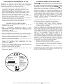
C D L
Class 2 Power Supply
Dimmable LED Driver
DC OUTPUT:
18-30
Regulated Current:350mA
CAUTION:
Risk of Electric Shock
Dry Areas Only
For Interior Use Only
____
_ _ _
4008390
•Tc
MODEL:
CDLP350R15
AC INPUT:
120 Vac/180 mA
60Hz PF >0.9
L-BLACK
N-WHITE
Made in China
C O N F O R M S
TO UL STD.1310
CERTIFIED TO CSA
TD C22.2 NO.233
MEETS ICES-003
Page is loading ...
Page is loading ...
Page is loading ...
Page is loading ...
-
 1
1
-
 2
2
-
 3
3
-
 4
4
-
 5
5
-
 6
6


EnviroLite EVL4732DSWH27 Installation guide
- Type
- Installation guide
- This manual is also suitable for
Ask a question and I''ll find the answer in the document
Finding information in a document is now easier with AI
in other languages
Related papers
-
EnviroLite EVL4730MWH35 Installation guide
-
-
-
-
-
-
-
-
EnviroLite EV608947WH27 Installation guide
-
EnviroLite RC7WHWH8102C User manual
Other documents
-
SUNCO WP_BR-3050K 80w Selectable Wall Pack Operating instructions
-
 Commercial Electric HBR70WH-12PK Installation guide
-
 Commercial Electric CER4730BWH40 Installation guide
-
 Commercial Electric HBR635WHA Installation guide
-
 Commercial Electric CER4741BWH30 Installation guide
-
Maxim 88272BGSST Installation guide
-
 Commercial Electric CER4742BWH30 Installation guide
-
 Commercial Electric CER4741WH Installation guide
-
 Commercial Electric CER4742ABN30 Installation guide
-


