Page is loading ...

FIG. 2
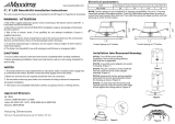
FIG. 1
FIG. 3 FIG. 4
OR
WARNING - RISK OF ELECTRIC SHOCK. DISCONNECT
MAIN POWER AT FUSE OR CIRCUIT BREAKER
BEFORE INSTALLING OR SERVICING THE FIXTURE.
RECESSED AND FLUSHMOUNT LED DOWNLIGHT
INSTALLATION INSTRUCTIONS - MODEL EVDSK690
QUESTIONS? CALL TOLL
FREE 1-855-373-6156
Please read carefully and save these instructions
as you may need them at a later date.
GENERAL: All electrical connections must be in accordance
with local and National Electrical Code (N.E.C.) standards. If
you are unfamiliar with proper electrical wiring connections
obtain the services of a qualified electrician.
Remove the trim from the box and make sure that no parts are
missing by referencing the PARTS illustrations.
THIS RETROFIT ASSEMBLY IS ACCEPTED AS A
COMPONENT OF A LED LUMINAIRE WHERE THE
SUITABILITY OF THE COMBINATION SHALL BE
DETERMINED BY CSA OR CANADIAN AUTHORITIES
HAVING JURISDICTION.
_________________________________________________
WARNING- RISK OF FIRE OR ELECTRIC SHOCK
FOR USE AS EITHER OF THE TWO OPTIONS BELOW:
1. A LED TRIM RETROFIT LUMINAIRE WITH APPROVED
TYPE IC OR NON-IC RECESSED LUMINAIRES THAT ARE
5 – 6 INCHES IN DIAMETER AND HAVE A DEPTH OF 5 –
7 INCHES.
2. A FLUSH MOUNT LED FIXTURE ON AN OUTLET BOX
WHICH IS SUITABLE FOR INSTALLING IN
WET-LOCATIONS.
• Do not alter, relocate, or remove wiring, lampholders, power
supply, or any other electrical component. Installation of the
retrofit assembly requires a person familiar with the
construction and operation of the luminaire’s electrical
system and the hazard involved. If not qualified, do not
attempt installation. Contact a qualified electrician.
• Do not make or alter any open holes in an enclosure of
wiring or electrical components during kit installation.
• To prevent wiring damage or abrasion, do not expose wiring
to edges of sheet metal or other sharp objects.
____________________________
ASSEMBLY AND INSTALLATION
1. If used as LED retrofit trim into approved recessed CAN,
attach torsion springs to mounting bracket and fasten with
the screws provided. Push in mounting bracket to spring
bracket located on top of LED luminaire. (FIG 1 & 2)
INCANDESCENT HOUSINGS
1. Unscrew the WING NUT inside the CAN to detach the
SOCKET BRACKET from the CAN. Disengage the
SOCKET from the SOCKET BRACKET. (FIG. 3)
2. Thread the SOCKET ADAPTER into the SOCKET. (FIG. 4)
5 in. – 6 in.
PARTS
SOCKET ADAPTER
ASSEMBLY
RETROFIT TRIM
COMPATIBLE HOUSING
DIMENSIONS
5 in. – 7 in.
OR

3. Plug the FEMALE CONNECTOR of the RETROFIT
TRIM onto the MALE CONNECTOR of the SOCKET
ADAPTER ASSEMBLY. (FIG. 5)
4. If using TORSION SPRINGS, squeeze both TORSION
SPRING arms together and insert into the TORSION
SPRING SLOTS (or C-CLIPS) of the CAN. (FIG. 6)
5. Tuck all wires into the CAN and carefully push the
RETROFIT TRIM into CAN. (NOTE: To provide
enough room in shallow cans, carefully position
SOCKET ADAPTER and SOCKET adjacent to the
side of the LED DRIVER prior to inserting
the RETROFIT TRIM into the CAN.) (FIG. 4 & 6)
LED HOUSINGS
1. Plug the FEMALE CONNECTOR of the RETROFIT
TRIM onto the MALE CONNECTOR of the HALO
HOUSING. (FIG. 5)
2. If using TORSION SPRINGS, squeeze both TORSION
SPRING arms together and insert into the TORSION
SPRING SLOTS (or C-CLIPS) of the CAN. Tuck all
wires into the CAN and carefully push the RETROFIT
TRIM into CAN. (FIG. 6)
JUNCTION BOX INSTALLATION
1. Use wire nut to make ground wire connection between
mounting bracket to existing junction box. Fasten
mounting bracket to junction box. (FIG. 7)
2. Cut off the E-26 screw base from socket adaptor
provided with this luminaire. (FIG. 8)
3. Use wire nuts to connect male end of connector of
adaptor with supply wires (black-to-black and white-to-
white). (FIG. 9)
4. Connect the quick connect from the junction box to the
quick connect on the fixture. (Fig. 9)
5. Tuck all wires into junction box, then align spring
bracket with center hole of the mounting bracket and
push the luminaire into junction box. (FIG. 10)
FIG. 5
FIG. 6
FIG. 8
FIG. 7
FIG.10
FIG. 9

________
DIMMING
For a complete list of compatible dimmers, please look up the
item number at www.envirolite-LED.com.
_____________________________
FIVE-YEAR LIMITED WARRANTY
EnviroLite
warrants this product to be free from defects in
material and workmanship for five years from the original date
of purchase by the consumer. This warranty is limited to the
counter replacement at the time of purchase, with the original
purchase receipt. EnviroLite
will not be liable for the loss or
damage of any kind, incidental or consequential damages of
any kind, whether based on warranty contract or negligence,
and arising in connection with the sale, use or repair of the
product claimed to be defective. Some states do not allow the
exclusion or limitation of incidental or consequential damages
so the above limitation may not apply to you. This warranty
gives you specific legal rights and you may also have other
rights, which vary from state to state. Misuse, accident,
improper installation or maintenance will also void the warranty.
_____________________________
This device complies with part 15 of the FCC Rules. Operation is
subject to the following two conditions:
1.This device may not cause harmful interference, and
2.This device must accept any interference received, including
interference that may cause undesired operation.
NOTE: This equipment has been tested and found to comply
with the limits for a Class B digital device, pursuant to Part 15 of
the FCC Rules. These limits are designed to provide reasonable
protection against harmful interference in a residential installation.
This equipment generates, uses and can radiate radio frequency
energy and, if not installed and used in accordance with the
instructions, may cause harmful interference to radio
communications. However, there is no guarantee that
interference will not occur in a particular installation. If this
equipment does cause harmful interference to radio or television
reception, which can be determined by turning the equipment off
and on, the user is encouraged to try to correct the interference
by one or more of the following measures:
• Reorient or relocate the receiver antenna.
• Increase the separation between the equipment and
receiver.
• Install the product onto on a circuit different from that to
which the receiver is connected.
• Consult with the dealer or an experienced radio/TV
technicianfor help.
CAUTION: Any changes made to the electronics circuit will void
this equipment’s compliance with Part 15 of the FCC Rules and
should not be operated.
_____________________________
Cumple con la norma ICES-CAN 3 (B) / NMB-3 (B)
_________________________
LIGHT DISTRIBUTION MAP.
-/+180
90
30
60
-30
120
150
-90
-60
-120
-150
0
60
120
180
240
300
/