Syntax LT26HVX Series User manual
- Category
- LCD TVs
- Type
- User manual
This manual is also suitable for

LCD Multi-Media Display
LT26HVE / LT26HVX Series
MK0-UM00061-000

Table of Contents
Important Information
Important Safety Precautions
FCC Statement
Accessories
Installation And Connection Guide
Identifying Front Controls and Rear Inputs
-Descriptions of Input Types
-Connecting the TV's Power
Installation
-
-Connecting to a VCR
-Connecting to an Audio Receiver/Home Theater System
-
-Connecting to a DVD Player with Component Cables
-Connecting to a Satellite Receiver or Cable Box with A/V Cables
-
-Connecting to a PC with VGA, and a DVD Player with DVI/HDCP Cables
-Other Connections
Remote Control Guide
-Regular Buttons
-Hotkeys Tutorial
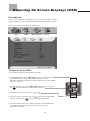
Adjusting the On Screen Display (OSD)
Introduction
To Operate in the OSD
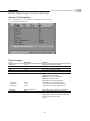
VIDEO Adjusting TV Picture Settings
- Adjusting Picture Quality
- Video Settings
- To Adjust Settings
- Auto Setting : Return to Default Factory Settings
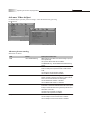
AUDIO Adjusting Sound Quality
- OSD Audio Settings : Reverb
- OSD Audio Settings : Equalizer
- MTS System for Stereo TV
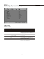
MISCELLANEOUS Adjusting Personal TV Settings
- Description of Settings
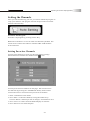
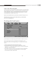
- Setting the Channels
- Personal Channel Preferences : Favorites
- Personal Channel Preferences : Channel Skip/Lock
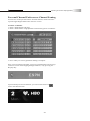
- Personal Channel Preferences : Channel Naming
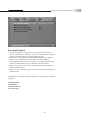
- Setting up the TV Timer
- Watching with Closed Caption
- TV OSD Languages
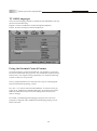
- Using the Parental Control Feature
- Parental Control
- Activating the Parental Control Feature
- To Block Unrated Channels
- Setting up Parental Control Password
- Factory Default Option
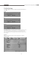
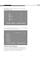
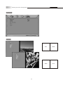
SCREEN Adjusting Screen Modes
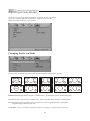
- Changing the Screen Mode
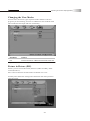
- Picture in Picture (PIP)
- PIP Mode
- Split Screen
- Split Screen Mode
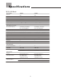
Specifications
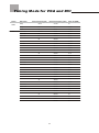
Timing Mode for VGA and DVI
Pixels Policy
Glossary
Connecting to an Antenna or Video Equipment with Antenna outlet
Connecting to a DVD Player with A/V or S Video Cables
Connecting to a Satellite Receiver or Cable Box With Component Connectors
1
2
5
6
8
10
11
12
13
14
15
16
17
18
19
20
21
22
23
25
25
26
26
26
29
29
30
31
31
32
33
33
34
34
35
36
37
38
39
39
40
40
42
42
44
45
45
46
48
49
50
51
53
55
56

01
Important information
Read the following context indicated by the following
symbol to the left. It indicates important literature in
operating the product.
Read the following context indicated by the following
symbol to the left. It indicates a potential high voltage
hazard that may compromise your safety.
Risk of electronic shock
Do not open
Caution
Caution
Take caution when moving the product on a cart.
Quick stops, excessive force, and uneven surfaces may
cause the display unit and cart combination to overturn.
Caution
To prevent electric shock, match wide blade of plug to wide slot,
fully insert.
Caution
This product satisfies FCC regulations when shielded cables and
connectors are used to connect the unit to other equipment.
Prevent electromagnetic interference from electrical appliances
such as radios and televisions. Please use shielded cables and
connectors for connections.
Warning
FCC Regulations state that any unauthorized changes or
modifications to this equipment not expressly approved by the
manufacturer could void the user's authority to operate this
equipment.
To reduce the risk of electronic shock, do not remove cover (or back).
No user-serviceable parts inside.
Refer service to qualified Repair Technician or Repair Center.

02
Important safety precautions
Cleaning
Remember to unplug the AC cord from the AC outlet
before cleaning the display unit. And do not use
liquid cleaners or aerosol cleaners to clean the
display.
Stand
Do not place the display unit on an unstable place.
The TV may fall resulting in serious personal
injuries to nearby people as well as damage to the
display unit.
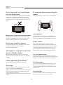
Ventilation
Do not cover or block these vents and openings located
on the top and back of the display. Inadequate ventilation
may cause overheating and shorten the lifespan of the display.
Do not place in an enclosed area such as a built-in shelf,
unless proper ventilation is provided or the manufacturer's
instructions are followed. Keep the distance of 10cm
minimum between the display unit and wall. Never install the
display unit as indicated in the picture below.
Air circulation is blocked
Air circulation is not blocked
10cm
10cm

03
Important safety precautions
Never insert objects or spill liquid
into the display unit
Never insert any object into the display unit through
openings or spill liquid on the display unit. High
voltage flows in the display unit, and inserting an
object can cause electric shock and/or short internal
parts.
Keep away from water and moisture
Do not place the display in areas where moisture is
present or where the unit may get wet such as bath-
rooms, kitchen, pool area or in a wet basement.
AC cord protection
The AC cords must be routed properly to prevent
people from stepping on them or objects from resting
on them. Check the cords at the plugs and product.
Keep away from heat sources
Keep the display unit away from heat sources such
as radiators, heaters, stoves and other
heat-generating products.
The liquid crystal panel used in this
product is made of glass
Do not hit the panel. Be careful to prevent from
getting hurt by broken glass pieces in case the panel
breaks.
Follow operating instructions
All operating instructions must be followed.
Precautions when transporting the
display
Carrying the display requires two or more people.
Attachments
Do not use attachments not recommended by the
manufacturer. Use of inadequate attachments may
result in accidents to nearby poeple or to the unit.
Power source
This product must operate on a power source
specified on the specification label. If you are not
sure of the type of power supply used in your home,
consult your dealer or local power company. For
units designed to operate on batteries or another
power source, refer to the operating instructions.
Overloading
Do not overload AC outlets or extension cords. It
may result in electric shock or start a fire.
Wall mounting
Be sure to install the display unit according to the
method recommended by the manufacturer. Use
only the mounting hardware recommended by the
manufacturer.
Servicing
Do not attempt to service the display unit yourself
unless specified by the manufacturer.
Failure to this rule will void the warranty of the unit.
Removing covers expose you to high voltage and
other dangerous conditions.
Request a qualified service technician to perform the
service.

04
Safety checks
Upon completion of service or maintenance, request
the service technician to perform safety checks to
ensure that the display unit is in proper operating
condition.
Environment
The display unit only operates within the
temperature 0C to 40 C.Operation outside of the
recommended may cause damage to your product.
Replacement parts
In case the display unit needs replacement parts,
make sure that the service technician uses replacement
parts specified by the manufacturer, or those with
the same characteristics and performance as the
original parts. Use of unauthorized parts can result
in fire, electric shock and/or other danger.
Repair
When the display unit displays an abnormal
condition, any noticeable abnormality in the display
unit indicates that the display unit needs servicing.
If any of the following conditions occurs, unplug
the AC cord from the AC outlet, and request a
qualified service person to perform repairs.
1.A liquid was spilled on the display unit or objects
have fallen into the display unit.
2.The display unit has been exposed to rain or water.
3.The display unit has been dropped or damaged.
Important safety precautions

05
FCC Statement
FCC notice
This equipment has been tested and found to comply with the limits for
a Class B digital device, pursuant to part 15 of the FCC Rules. These
limits are designed to provide reasonable protection against harmful
interference in a residential installation. This equipment generates, uses
and can radiate radio frequency energy and, if not installed and used in
accordance with the instructions, may cause harmful interference to radio
communications. However, there is no guarantee that interference will
not occur in a particular installation. If this equipment does cause
harmful interference to radio or television reception, which can be
determined by turning the equipment off and on, the user is encouraged
to try to correct the interference by one or more of the following
measures:
1.Reorient or relocate the receiving antenna.
2.Increase the separation between the equipment and receiver.
3.Connect the equipment into an outlet on a circuit different from that to
which the receiver is connected.
4.Consult the dealer or an experienced radio/TV technician for help.
Modifications not expressly approved by the manufacturer could void
the user's authority to operated the equipment under FCC rules. This
device complies with part 15 of the FCC Rules. Operation is subject to
the following two conditions:
1.This device may not cause harmful interference.
2.This device must accept any interference received, including
interference that may cause undesired operation.
For Canadian model
This Class B digital apparatus complies with Canadian ICES-003.
Approval

06
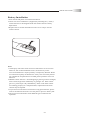
Accessories
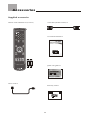
Supplied accessories
Remote control & batteries (AAA x 2)
Power cord x 1
VGA cable (D-Sub 15 male) x 1
User manual booklet x 1
Quick start guide x 1
Warranty card x 1
LCD Multi-Media Display
LT26HVE /LT26HVX Series
Quick Start Guide
LCD Multi-Media Display
LT26HVE/LT26HVX Series

07
Accessories
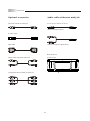
Optional accessories
AV cable with RCA connector
S-video cable
DVI cable
Audio cable with RCA connector
Audio cable with stereo mini jack
Use the proper cable for the device.
( Stereo mini jack cable )
( Stereo mini jack to RCA cable )
Wall mount set
Model# WM-20D
Component cable with RCA connector

08
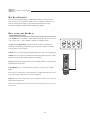
TV Installation and Connection Guide
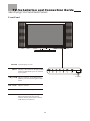
Identifying Front and Rear Panels
Turns display on / off
Displays the On Screen Display(OSD)
menu. In OSD menu, press it to return
to pre-phase
Adjusts Channel. In the OSD menu,
both keys are used to navigate within
menu
Adjusts volume
Press to switch the input sources
Contains Infra-red light for digital
data transmission by the remote
control. Please point remote control
at IR Sensor for function
POWER
MENU
VOL+/VOL-
SOURCE
IR SENSOR
CH / CH
Front Panel
IR Sensor

09
TV Installation and Connection Guide
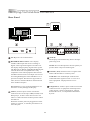
Identifying Front and Rear Connectors
Rear Panel
L
L
R
R
S-VIDEO
S-VIDEO
VIDEO
VIDEO
EarPhone
L R
ANT
Y
Y
Pb / Cb
Pb / Cb
Pr / Cr
Pr / Cr
L
L
R
R
Component2
VIDEO-1
VIDEO-2
Audio Output
Component1
DVI / HDCP
R
L
Service
Port
VGA
AC IN power cord connects here.
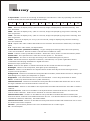
DVI/HDCP and VGA Port : This display
includes a DVI input that receives analog or
digital video signals through the interface for
the display of high quality digital video signals.
The DVI port is HDCP (High Bandwidth Digital
Content Protection) compliant and is fully
compatible with video equipment that features
the HDCP function. The VGA input can be used
for analog RGB signals from a HD Receiver or
personal computer. Resolutions supported are
VGA, SVGA, XGA and WXGA. DVI and VGA
share Audio L/R inputs.
Service Port is reserved for manufacturer use.
Incorrect use may damage the Display.
Video 1,2 These inputs can be used for the
connection of a VCR, Super VHS (S-VHS) VCR,
DVD player, or other video devices to the TV.
There is a Video and an S-Video input for Video1
and Video 2.
When the S-Video jacks are plugged into either
Video 1 or Video 2, it will take precedence over
the Video jack.
(Cont'd)
The display will automatically detect the input
jack being used.
NOTE: The S-Video input has a better quality of
picture than a composite Video signal.
Antenna (ANT) Antenna receives signals from
VHF/ UHF antennas or a cable system.
Audio Out The Audio Output sends the TV's
connected audio signals to an A / V receiver or
other equipment. Display features a R / L
stereo.
Component 1, 2 These inputs can be used for the
connection of A / V equipment with component
video outputs, such as a DVD player, Digital
Satellite Receiver, or compatible Video Game
System.

10
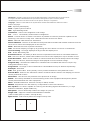
Descriptions of Connector Types
You may find it necessary to use some of the following connector types during setup.
75-ohm coaxial cable Used for TV cable connection .
S-Video Cable High quality video cable for enhanced picture quality.
Video Yellow
Audio (Left) White
Audio (Right) Red
Some DVD players are equipped with the following three video connectors:
Audio/Video Cable
Y- Green
Pb/Cb - Blue
Pr/Cr - Red
TV Installation and Connection Guide

11
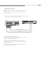
Connecting the Power Cord
Complete other connections prior to connecting the power cord:
1.Connect the power cord to the AC IN connector of the TV
TV Installation and Connection Guide
2.Connect the other end of the power cord to the wall outlet.

12
Installation
TV Installation and Connection Guide
In the following pages, you will find directions on how to install your tv and choice of video equipment.
Connecting to an Antenna or Video Equipment with Antenna outlet
Connecting to a DVD Player with A/V or S-Video Cables
Connecting to a Satellite Receiver or Cable Box With Component Connectors
Connecting to a VCR
Connecting to an Audio Receiver/Home Theater System
Connecting to a DVD Player with Component Cables
Connecting to a Satellite Receiver or Cable Box with A/V Cables
Connecting to a PC with VGA, and a DVD Player with DVI / HDCP Cables
Other Connections

13
TV Installation and Connection Guide
Connecting to an Antenna or Video Equipment
with Antenna outlet
1.Connect a 75ohm coaxial cable onto the ANT input on the back of the
TV's right side panel.
If connecting to Video Equipment with Antenna outlet
1.Using a 75-ohm coaxial cable (or choice of Antenna Cable), connect
the cable box's OUT jack to the TV's ANT jack (RF Terminal).
Disconnect all power sources before making any connection.
Video Equipment with
Antenna In/Out Socket
IN
jack
OUT
jack
75-ohm coaxial cable
L
L
R
R
S-VIDEO
S-VIDEO
VIDEO
VIDEO
EarPhone
L R
ANT
Y
Y
Pb / Cb
Pb / Cb
Pr / Cr
Pr / Cr
L
L
R
R
Component2
VIDEO-1
VIDEO-2
Audio Output
Component1
Rear of TV
75-ohm coaxial cable
L
L
R
R
S-VIDEO
S-VIDEO
VIDEO
VIDEO
EarPhone
L R
ANT
Y
Y
Pb / Cb
Pb / Cb
Pr / Cr
Pr / Cr
L
L
R
R
Component2
VIDEO-1
VIDEO-2
Audio Output
Component1
Rear of TV
75-ohm coaxial cable

14
TV Installation and Connection Guide
Connecting to a VCR
Use this hookup if you subscribe to a cable TV system that does not
require a cable box.
1.Using A/V cable and S-Video cables, connect the VCR's Audio and S Video
OUT jacks to the TV's Audio and S-Video In jacks.
Connecting both Video IN or S-Video IN
Note:
Note:
Use this method of connection if you subscribe to a cable TV
system that does not require a cable box.
S-Video is strongly recommended for use if your VCR or video
equipment has it. S-Video input has a better quality of picture than a
composite Video signal.
You can also use the Video 2 jacks located on the TV rear to
connect additional video equipment.
Disconnect all power sources before making any connections.
L
L
R
R
S-VIDEO
S-VIDEO
VIDEO
VIDEO
EarPhone
L R
ANT
Y
Y
Pb / Cb
Pb / Cb
Pr / Cr
Pr / Cr
L
L
R
R
Component2
VIDEO-1
VIDEO-2
Audio Output
Component1
A/V cable with RCA connector
S Video cable
VCR
Rear of TV

15
TV Installation and Connection Guide
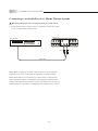
Connecting to an Audio Receiver
1.Using an audio cable, connect the TV's audio OUT jack to the audio
receiver's audio IN or AUX IN jacks.
/ Home Theater System
Note: When connecting an Audio output signal, an external Audio
amplifier is necessary to amplify the signal for external speakers.
Note: If the audio out is hooked up to a home theatre sound system,
please disable the audio in the OSD by selecing off in audio section .
Volume adjustment must be made on the home theatre receiver. By not
disabling the TV's speaker it could damage the speakers or TV itself.
Disconnect all power sources before making any connections.
Audio cable
Audio Receiver
Rear of TV
RedWhite
L
L
R
R
S-VIDEO
S-VIDEO
VIDEO
VIDEO
EarPhone
L R
ANT
Y
Y
Pb / Cb
Pb / Cb
Pr / Cr
Pr / Cr
L
L
R
R
Component2
VIDEO-1
VIDEO-2
Audio Output
Component1

16
TV Installation and Connection Guide
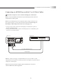
Connecting to a DVD Player with A/V or S-Video Cables
Note: If your DVD player has component video output connectors, for
best picture quality, use the connection described for Connecting to a
DVD Player With Component Connectors.(See page.17)
1.Using an A/V cable, connect the DVD player's Audio OUT jacks to
the TV's Audio IN jacks.
2.Using an S-Video Cable, connect the DVD player's S-Video OUT jack
to the TV's S-Video IN jack.
Note: Use this method of connection if your DVD player does not have
component (Y, Pb,Pr) jacks.
Note:
You can also use the Video 2 jacks located on the TV rear to
connect additional video equipment.
S-Video is strongly recommended for use if your VCR or video
equipment has the option .S-Video input has better quality of picture than a
composite Video signal.
Note:
Disconnect all power sources before making any connections.
DVD player
L
L
R
R
S-VIDEO
S-VIDEO
VIDEO
VIDEO
EarPhone
L R
ANT
Y
Y
Pb / Cb
Pb / Cb
Pr / Cr
Pr / Cr
L
L
R
R
Component2
VIDEO-1
VIDEO-2
Audio Output
Component1
A/V cable with RCA connector
S Video cable
Rear of TV

17
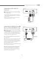
TV Installation and Connection Guide
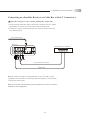
Connecting to a DVD Player With Component Cables
1.Using a component video cable, connect the DVD Player's Y, Pb and
Pr jacks to the Y, Pb and Pr jacks on the TV.
Colors on Component Video connectors:
Y: Green
Pb (also identified as Cb, CB or B-Y): Blue
Pr (also identified as Cr, CR or R-Y): Red
Note: The Y, Pb and Pr jacks on your DVD player are sometimes labeled
as Y, Cb and Cr, or B-Y and R-Y. If so, connect the cables to the
matching colors.
2.Using an Audio cable, connect the DVD player's Audio OUT jacks to
the TV's Audio in jacks.
Note: Use this method of connection if your DVD Player has component
(Y, Pb, Pr) jacks.
Note: The Y, Pb and Pr jacks do not provide audio, so audio cables must
be connected to provide sound.
Note: The YPbPr connection provides the best quality of video signal
compared to AV (Composite) and S-Video connection.
Disconnect all power sources before making any connections.
Component cable with RCA connector
DVD player
L
L
R
R
S-VIDEO
S-VIDEO
VIDEO
VIDEO
EarPhone
L R
ANT
Y
Y
Pb / Cb
Pb / Cb
Pr / Cr
Pr / Cr
L
L
R
R
Component2
VIDEO-1
VIDEO-2
Audio Output
Component1
Rear of TV
Audio cable

18
TV Installation and Connection Guide
Connecting to a Satellite Receiver or Cable Box with A/V Connectors
1.Using Audio and S Video cables, connect the satellite receiver's Audio
and S Video OUT jacks to the TV Audio and S Video IN jacks.
2.Connect a 75-ohm coaxial cable from your cable or antenna to the TV
Ant (Antenna) jack.
Note: S-Video is strongly recommended for use if your VCR or video
equipment has it because S-Video input has better quality of picture than
a composite Video signal.
Note: You can also use the Video 2 jacks located on the TV rear to connect
additional video equipment.
Disconnect all power sources before making any connections.
L
L
R
R
S-VIDEO
S-VIDEO
VIDEO
VIDEO
EarPhone
L R
ANT
Y
Y
Pb / Cb
Pb / Cb
Pr / Cr
Pr / Cr
L
L
R
R
Component2
VIDEO-1
VIDEO-2
Audio Output
Component1
A/V cable with RCA connector
S Video cable
Rear of TV
Satellite Receiver or Cable Box
75-ohm coaxial cable
Page is loading ...
Page is loading ...
Page is loading ...
Page is loading ...
Page is loading ...
Page is loading ...
Page is loading ...
Page is loading ...
Page is loading ...
Page is loading ...
Page is loading ...
Page is loading ...
Page is loading ...
Page is loading ...
Page is loading ...
Page is loading ...
Page is loading ...
Page is loading ...
Page is loading ...
Page is loading ...
Page is loading ...
Page is loading ...
Page is loading ...
Page is loading ...
Page is loading ...
Page is loading ...
Page is loading ...
Page is loading ...
Page is loading ...
Page is loading ...
Page is loading ...
Page is loading ...
Page is loading ...
Page is loading ...
Page is loading ...
Page is loading ...
Page is loading ...
Page is loading ...
Page is loading ...
Page is loading ...
Page is loading ...
-
 1
1
-
 2
2
-
 3
3
-
 4
4
-
 5
5
-
 6
6
-
 7
7
-
 8
8
-
 9
9
-
 10
10
-
 11
11
-
 12
12
-
 13
13
-
 14
14
-
 15
15
-
 16
16
-
 17
17
-
 18
18
-
 19
19
-
 20
20
-
 21
21
-
 22
22
-
 23
23
-
 24
24
-
 25
25
-
 26
26
-
 27
27
-
 28
28
-
 29
29
-
 30
30
-
 31
31
-
 32
32
-
 33
33
-
 34
34
-
 35
35
-
 36
36
-
 37
37
-
 38
38
-
 39
39
-
 40
40
-
 41
41
-
 42
42
-
 43
43
-
 44
44
-
 45
45
-
 46
46
-
 47
47
-
 48
48
-
 49
49
-
 50
50
-
 51
51
-
 52
52
-
 53
53
-
 54
54
-
 55
55
-
 56
56
-
 57
57
-
 58
58
-
 59
59
-
 60
60
-
 61
61


Syntax LT26HVX Series User manual
- Category
- LCD TVs
- Type
- User manual
- This manual is also suitable for
Ask a question and I''ll find the answer in the document
Finding information in a document is now easier with AI
Other documents
-
 Olevia LT32HVM Series User manual
-
 Olevia LT20S User manual
-
 Olevia LT37HVS User manual
-
 Olevia LT37HVS User manual
-
 Olevia LT42HVi User manual
-
 Olevia LT26HVE User manual
-
ProScan PLDED3257A-B Operating Instructions Manual
-
Magnavox 42MF230A/37B User manual
-
Westinghouse LTV-17v1 Owner's manual
-


