Page is loading ...

BUEZ3 SERIES
RANGE HOOD
READ AND SAVE THESE INSTRUCTIONS
WARNING
TO REDUCE THE RISK OF FIRE, ELECTRIC SHOCK, OR INJURY
TO PERSONS, OBSERVE THE FOLLOWING:
1. Use this unit only in the manner intended by the manufacturer. If
you have questions, contact the manufacturer at the address or
telephone number listed in the warranty.
2. Before servicing or cleaning unit, switch power off at service panel
and lock service panel to prevent power from being switched on
accidentally. When the service disconnecting means cannot be
locked, securely fasten a prominent warning device, such as a
tag, to the service panel.
3. Installation work and electrical wiring must be done by a qualified
person(s) in accordance with all applicable codes and standards.
4. Sufficient air is needed for proper combustion and exhausting of
gases through the flue (chimney) of fuel burning equipment to
prevent backdrafting. Follow the heating equipment manufacturer’s
guideline and safety standards such as those published by the
National Fire Protection Association (NFPA), and the American
Society for Heating, Refrigeration and Air Conditioning Engineers
(ASHRAE), and the local code authorities.
5. When cutting or drilling into wall or ceiling, do not damage electrical
wiring and other hidden utilities.
6. Ducted fans must always be vented to the outdoors.
7. Do not use this unit with any solid-state speed control device.
8. To reduce the risk of fire, use only metal ductwork.
9. Use with approved cord-connection kit only.
10.This unit must be grounded.
TO REDUCE THE RISK OF A RANGE TOP GREASE FIRE:
1. Never leave surface units unattended at high settings. Boilovers
cause smoking and greasy spillovers that may ignite. Heat oils
slowly on low or medium settings.
2. Always turn hood ON when cooking at high heat or when cooking
flaming foods.
3. Clean ventilating fans frequently. Grease should not be allowed
to accumulate on fan or filter.
4. Use proper pan size. Always use cookware appropriate for the
size of the surface element.
TO REDUCE THE RISK OF INJURY TO PERSONS IN THE EVENT
OF A RANGE TOP GREASE FIRE, OBSERVE THE FOLLOWING:*
1. SMOTHER FLAMES with a close-fitting lid, cookie sheet, or metal
tray, then turn off the burner. BE CAREFUL TO PREVENT BURNS.
If the flames do not go out immediately, EVACUATE AND CALL
THE FIRE DEPARTMENT.
2. NEVER PICK UP A FLAMING PAN - You may be burned.
3. DO NOT USE WATER, including wet dishcloths or towels - a violent
steam explosion will result.
4. Use an extinguisher ONLY if:
A. You know you have a Class ABC extinguisher and you already
know how to operate it.
B. The fire is small and contained in the area where it started.
C. The fire department is being called.
D. You can fight the fire with your back to an exit.
*Based on “Kitchen Firesafety Tips” published by NFPA.
CAUTION
1. For indoor use only.
2. For general ventilating use only. Do not use to exhaust hazardous
or explosive materials and vapors.
3. To avoid motor bearing damage and noisy and/or unbalanced
impellers, keep drywall spray, construction dust, etc. off power unit.
4. For best capture of cooking impurities, your range hood should
be mounted 20-25” above the cooking surface.
5. Please read specification label on product for further information
and requirements.
IMPORTANT: OBSERVE ALL GOVERNING CODES AND
ORDINANCES
Your range hood has been designed to filter out smoke, odors, and
grease which rise from the cooking surface. Before you begin the
installation be sure that all parts and accessories are removed from
carton. For best results and ease in the installation of this range hood,
read the instructions sheet to become familiar with the step-by-step
installation.
TOOLS AND MATERIALS REQUIRED
Drill, electric or ratchet drive
1/8" drill bit for drilling pilot holes
7/64" drill bit to drill holes for EZ1 brackets mounting screws
1-1/4" wood bit for drilling electrical wiring access hole
One common head screwdriver for securing hood mounting screws
to the cabinet and hood sheet metal parts
Pliers for opening knockouts
Pencil, rule and level for marking cabinet locations
Saber saw or keyhole saw for cutting the wall or cabinet openings
Metal snips, duct tape, duct (with elbows and transition, if
necessary), roof cement or caulk, and roof or wall cap, as required
Electrical wiring and supplies of type to comply with local codes
The following materials are required only for installation on recessed
bottom kitchen cabinets:
Two 1" x 2" x 12" (approximate length) wood strips (purchase
locally)
Four 1-1/4" long flat head wood screws (purchase locally)
INSTALLER:
LEAVE THIS MANUAL WITH THE HOMEOWNER.
HOMEOWNER:
USE AND CARE INSTRUCTIONS ON PAGE 5.
!
INTENDED FOR DOMESTIC COOKING ONLY
!
Register this product at
www.broan.com/register.
To order Service Parts: go to www.broan.com

2
LIGHT LENS
ALUMINUM OR
COMBINATION
FILTER
JUNCTION BOX
PREPARING THE HOOD
1. Unpack hood and check contents. You should receive:
1 – Filter with built-in light lens
1 – 3-1/4" x 10" damper/duct connector
1 – Installation parts bag, located inside junction box
2. Remove junction box cover, EZ1 brackets and parts bag from inside
junction box.
3. Remove top or rear electrical knockout. Install an appropriate strain
relief.
4. Select one of the three types of venting available:
Non-Vented — Remove vent
cover from hood front. Replace
the aluminum filter with a non-
ducted filter (BP57 or R610050
- purchase separately). Go
to "Preparing the Installation
Location".
Rectangular Vented — 3-1/4" x 10" vertical or horizontal. Remove
knockout
for vertical or knockout for horizontal venting. Install
damper/duct connector over opening. Go to "Planning Ductwork
Installation".
Round Vented — 7" vertical. Remove knockouts and exposing
duct collar. Go to "Planning Ductwork Installation".
PLANNING DUCTWORK
INSTALLATION
This section is for vented hoods only. For non-vented hoods, skip
this section and go to "Preparing the Installation Location".
Begin planning ductwork by deciding where duct will run between hood
and outside. For best performance, use shortest possible duct run and a
minimum number of elbows. There are several choices.
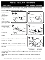
Ducting directly through the wall (for range hoods mounted on an
exterior wall). Shown are two ways to duct through an outside wall. If a
wall cap is used directly off the back of the hood, special care must be
taken to make sure that the damper in the damper/duct connector on
the hood and damper in the wall cap do not interfere with each other
when the hood is operating. This could result in either inadequate air
delivery or back drafts. If this condition does exist, remove the hood
damper flap. Sometimes when using a wall cap, it is easier to duct
vertically and then use an elbow.
Ducting straight up through roof using 3-1/4" x 10" or 7" round duct.
For single story installations.
Ducting between ceiling joists for multi-story installations or through
soffits above cabinets where soffit connects to outside walls.
INSTALLING THE DUCTWORK
THESE INSTRUCTIONS ARE FOR VENTED HOODS ONLY. FOR NON-
VENTED HOODS, SKIP THIS SECTION AND GO TO "INSTALLING
THE RANGE HOOD".
START AT THE EXTERIOR AND RUN DUCTWORK BACK TO THE
RANGE HOOD.
FOR BEST PERFORMANCE OF YOUR RANGE HOOD, USE THE
SHORTEST POSSIBLE DUCT RUN AND A MINIMUM NUMBER OF
ELBOWS.
NEVER VENT A RANGE HOOD INTO AN ATTIC SPACE BECAUSE A
BUILDUP OF GREASE WILL BECOME A FIRE HAZARD.
USE ONLY METAL DUCTWORK (DO NOT USE PLASTIC DUCT).
ASSEMBLE SECURELY SO THAT IN CASE OF A GREASE FIRE
ON THE RANGE, THE FIRE WILL BE CONTAINED INSIDE METAL
DUCTWORK.
IT IS A GOOD PRACTICE TO TAPE ALL DUCT CONNECTIONS,
MAKING THEM BOTH SECURE AND AIR TIGHT.
1. Follow appropriate directions below for type of ductwork you are
installing.
Wall Cap Discharge: Use saber saw or keyhole saw to cut hole slightly
larger than duct size used so that duct will line up easily with damper/duct
connector on hood. Install casing strips if cap will be installed on siding.
Attach required amount of duct to wall cap and run duct back to hood.
Fasten cap to wall and caulk well. Make sure that enough duct runs into
the room so that the duct will overlap the damper/duct connector when
the hood is installed.
VENT COVER
ROOF CAP
ROOF CAP
REMOVE THE
HOOD DAMPER
FLAP IF IT
INTERFERES
WITH THE WALL
CAP DAMPER
DAMPER
(INCLUDED)
BP87Q DAMPER (NOT
INCLUDED) LOCATED
AT LEAST 6" FROM
HOOD IN VERTICAL
SECTION OF DUCT

Roof Cap Discharge: Cut a hole in roof slightly larger than duct size being
used. Trim shingles around hole so that they will fit snugly around hood of
cap when cap is installed. Assemble the ductwork and tape all joints. Run
ductwork down to hood location. Make sure that enough duct runs into the
room so that the duct will overlap damper/duct connector when hood is put
into place. Leave 3/4" of duct projecting above roof surface on high side.
Trim duct parallel to roof pitch and seal all around duct with roof cement.
Carefully trim shingles and slide back of roof sheet under shingles. Nail
roof sheet to roof under shingles at top two corners and two sides. Nail
sheet directly to roof in four places at bottom.
Using roof cement, seal all nail heads and shingles which were cut or
lifted. Do not seal bottom edge of roof sheet.
PREPARING THE INSTALLATION
LOCATION
NOTE: MOUNT HOOD SO THAT BOTTOM OF HOOD IS 20" TO 25"
ABOVE COOKING SURFACE. TOP FRONT OF HOOD SHOULD BE
FLUSH WITH FRONT OF CABINET FRAME.
IF DISTANCE BETWEEN WALL AND FRONT OF CABINET FRAME
IS MORE THAN 12", THERE WILL BE A SPACE BETWEEN BACK OF
HOOD AND WALL. THIS IS NORMAL.
OMIT STEP 1 IF HOOD WILL BE INSTALLED UNDER CABINETS
WITH FLUSH BOTTOM OR INSTALLED USING THE EZ1 BRACKETS.
1. For cabinets with recessed bottoms only, if not using EZ1 brackets:
Install wood filler strips on each side of recessed area under cabinet.
Use two 1" x 2" strips cut to length (use thicker strips if necessary).
Fasten strips with wood screws about 3" in from each end.
2. Measure and mark the following:
a.) Electrical wiring opening in wall or cabinet.
b.) Duct opening in wall or cabinet (vented hoods only).
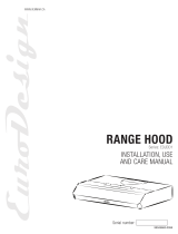
EZ-1 ONE-PERSON INSTALLATION SYSTEM
If the cabinet is wider than the range hood width, please use the
standard installation method.
Using pliers, break EZ1 brackets apart. Use the appropriate brackets
according to the kitchen cabinet type. Refer to the marking on the
brackets to determine the correct installation side and orientation.
Mate the corresponding bracket to the cabinet side frame, while
placing rear end of bracket against the wall. Use a pencil to mark 3
holes (there are 6 holes but only 3 are necessary).
Remove the bracket. Using a 7/64” drill bit, drill 3 holes where marked.
Assemble the bracket to the side frame using a Phillips screwdriver
and 3 provided round head no. 8 x 5/8” wood screws. Repeat for the
other side frame.
FRAMED
CABINET
7/64”
XY
Z
INSTALLING THE RANGE HOOD
This manual covers 2 kinds of installation: the standard (without EZ1
brackets) and the EZ1 one-person installation system. For the standard
installation, go to page 4.
3
FILLER STRIP
WARNING: WHEN CUTTING OR DRILLING INTO WALL OR CABINET,
BE CAREFUL NOT TO CUT EXISTING ELECTRICAL WIRING.
3. Drill 1-1/4" electrical wiring opening in wall or cabinet bottom.
4. Drill four pilot holes in corners of marked duct opening and cut opening
with saber or keyhole saw (vented hoods only).
CABINET CUTOUTS
3-1/4" x 10"
RECTANGULAR
VENTING
CABINET CUTOUTS
7" ROUND
VENTING
5"
4"
1½"
5¼"
5¼"

FRAMELESS
CABINET
[ \
7/64”
X
3 X
Y
Z
Align the corresponding bracket to the cabinet side, while placing
rear end of bracket against the wall. Draw a line on the outer edge
of the bracket (as shown).
Slide the bracket towards the center of cabinet and align the outside
edge of the bracket with the marked line, keeping the rear end edge
leaning on the wall.
Use a pencil to mark 3 holes.
Remove the bracket. Using a 7/64” drill bit, drill 3 holes where marked.
Assemble the bracket to the cabinet bottom using a Phillips
screwdriver and 3 provided countersunk wood screws. Repeat for
the other cabinet side.
The following procedure applies to both framed or frameless
cabinet installations.
HORIZONTAL EXHAUST INSTALLATION ONLY
1. Pull house power cable out.
2. Temporarily hang the hood on the brackets using its 2 recessed
REAR HOLES (A and B). While holding the hood, run the house
power cable into the hood through the strain relief previously installed.
3. Unhook the rear holes from the brackets and hang the hood using
its 2 recessed FRONT HOLES. While holding the hood, attach the
power cable to the hood using the strain relief.
VERTICAL EXHAUST INSTALLATION ONLY
1. Pull house power cable out.
2. Hang the hood on the brackets using the 2 recessed FRONT
HOLES. While holding the hood, run the house power cable into
the hood through the strain relief previously installed. Attach power
cable to the hood.
A
B
For framed cabinet, secure the hood to the EZ1 brackets using
4 no. 8-18 x 1/2” metal screws (included). Insert 2 screws per side,
in the slots.
For frameless cabinet, secure the hood to the cabinet using
4 no. 8 x 5/8” round head wood screws (included). Insert 2 screws per
side, in the slots.
STANDARD INSTALLATION
1. Hold hood up against cabinet bottom and trace keyhole slots onto
cabinet bottom or filler strips.
2. Screw the four supplied screws for mounting the hood into the exact
center of the narrow end of the keyhole slots marked underneath the
cabinet. Allow 3/8" of the screws to project, so the hood can be fitted
into place.
3. Run electric wiring through hole drilled in wall or cabinet. Split wiring
for 6" and run the house power cable into the hood through the strain
relief previously installed. Attach power cable to the hood.
4. Position hood so that:
a.) Large part of keyhole slots fit over hood mounting screws.
b.) Damper/duct connector slides into ductwork (3-1/4" x 10" vented
hoods only)
5. Adjust hood so that hood front is flush with cabinet frame.
6. Tighten hood mounting screws firmly.
CONNECT THE WIRING
WARNING: TURN OFF THE PROPER CIRCUIT AT THE SERVICE
ENTRANCE BEFORE WIRING THIS RANGE HOOD. ALL ELECTRICAL
CONNECTIONS MUST BE MADE IN ACCORDANCE WITH LOCAL
CODES, ORDINANCES, OR NATIONAL ELECTRICAL CODE. IF YOU
ARE UNFAMILIAR WITH METHODS OF INSTALLING ELECTRICAL
WIRING, SECURE THE SERVICES OF A QUALIFIED ELECTRICIAN.
1. Make electrical connection using wire nuts to connect WHITE wire
to WHITE, BLACK wire to BLACK, and GREEN or bare wire to GREEN
ground screw provided.
2. Replace wiring box cover and screw, taking care not to pinch wires.
KEYHOLE SLOT OUTLINE
FILLER
STRIPS
FRAMELESS
CABINET
FRAMED
CABINET
WOOD
SCREWS
METAL
SCREWS
4

FINALIZE THE INSTALLATION
1. Install light bulb (75 watts maximum).
2. If the hood is vented, remove charcoal filter pad from filter. Install filter.
3. Turn on power and check operation of fan and light. Make sure that
damper operates freely (vented hood only).
USE AND CARE
ALUMINUM FILTER
For greatest efficiency, the permanent-type aluminum filter should be
removed and cleaned periodically. To clean, the filter should be soaked
in hot water and detergent and thoroughly rinsed. The aluminum filter can
be cleaned in a dishwasher.
COMBINATION FILTER
This filter should be inspected periodically and when it becomes saturated,
it should be replaced. There are no effective means of reactivating this filter.
LIGHTS
Do not use bulb larger than 75 watts in light socket.
CARE OF EXTERIOR SURFACES
Clean your hood with a mild detergent suitable for painted surfaces. DO
NOT USE ABRASIVE CLOTH, STEEL WOOL PADS OR SCOURING
POWDERS.
WARNING: ALWAYS DISCONNECT ELECTRIC POWER BEFORE
SERVICING RANGE HOOD.
CARE OF FAN MOTOR
Fan motor has lifetime sealed bearings that never need oiling under normal
usage. A few drops on each bearing after three years of heavy usage will
prolong the motor life. Clean motor with a damp cloth and grease-cutting
detergent when a heavy coating of grease has accumulated.
REPLACEMENT PARTS
* Not shown. Purchase separately.
1
2
3
4
7
5
Replacement parts
can be ordered on our
website at
www.Broan.com
HOW TO AVOID A COMMON RANGE-TOP GREASE FIRE
Your range hood provides a protective barrier between the cooking
surface and the cabinets.
Keep fan, filters, and grease-laden surfaces CLEAN according to the
instructions.
Always turn hood ON when cooking at high heat to keep the cooking
area and the hood cooler.
Use high heat settings only when necessary.
Never leave cooking surface unattended. Boil-over causes smoking
and greasy spillovers that may ignite.
Always use adequate-sized utensils.
If preparing flaming foods, such as Cherries Jubilee, always turn
hood ON to HIGH to prevent a high heat situation which can cause
damage or fire.
HOW TO EXTINGUISH A COMMON RANGE-TOP GREASE FIRE
Never pick up a flaming pan. If dropped flames can spread quickly.
DO NOT USE WATER! A violent steam explosion may result. Wet
dishcloths or towels are also dangerous.
Smother flames with a close-fitting lid, cookie sheet or metal tray.
Flaming grease can also be extinguished with baking soda or a multi-
purpose dry chemical extinguisher.
Turn off surface units – if you can do so without getting burned.
5
Key No. Part No. Description
1
97016971 Fan & Light switches – White
97016970 Fan & Light switches – Black
2
R730090 Motor/Blade Assembly
3
R610045
Filter - Aluminum (use with ducted hoods only)
*
R610050 Filter – Ductless
*
R610051 Filter Pads – Ductless
4
R566088 Lampholder
5
99091020 Vent Cover - White
99091022 Vent Cover - Black
6
R6689601 Wiring Cover - White
R6689604 Wiring Cover - Black
*
S97021374 EZ1 Brackets

6
Limited Warranty
Warranty Period and Exclusions: Broan-NuTone LLC (the “Company”) warrants to the original consumer purchaser of its product (“you”) that the
product (the “Product”) will be free from material defects in the Product or its workmanship for a period of one (1) year from the date of original purchase
(or such longer period as may be required by applicable law).
The limited warranty period for any replacement parts provided by the Company and for any Products repaired or replaced under this limited warranty
shall be the remainder of the original warranty period (or such longer period as may be required by applicable law).
This warranty does not cover fluorescent lamp starters, tubes, halogen and incandescent bulbs, fuses, filters, ducts, roof caps, wall caps and other
accessories for ducting that may be purchased separately and installed with the Product. This warranty also does not cover (a) normal maintenance
and service, (b) normal wear and tear, (c) any Products or parts which have been subject to misuse, abuse, abnormal usage, negligence, accident,
improper or insufficient maintenance, storage or repair (other than repair by the Company), (d) damage caused by faulty installation, or installation or
use contrary to recommendations or instructions, (e) any Product that has been moved from its original point of installation, (f) damage caused by envi-
ronmental or natural elements, (g) damage in transit, (h) natural wear of finish, (i) Products in commercial or nonresidential use, or (j) damage caused
by fire, flood or other act of God or (k) Products with altered, defaced or removed serial numbers. This warranty covers only Products sold to original
consumers in the United States by the Company or its U.S. distributors authorized by the Company.
This warranty supersedes all prior warranties and, subject to applicable law, is not transferable from the original consumer purchaser.
No Other Warranties: This Limited Warranty contains the Company’s sole obligation and your sole remedy for defective products. The foregoing
warranties are exclusive and in lieu of any other warranties and conditions, express or implied. THE COMPANY DISCLAIMS AND EXCLUDES ALL
OTHER EXPRESS WARRANTIES AND CONDITIONS, AND DISCLAIMS AND EXCLUDES ALL WARRANTIES AND CONDITIONS IMPLIED BY
LAW, INCLUDING WITHOUT LIMITATION THOSE OF MERCHANTABILITY AND FITNESS FOR A PARTICULAR PURPOSE. To the extent that
applicable law prohibits the exclusion of implied warranties or conditions, the duration of any applicable implied warranty or condition is limited to the
period specified for the express warranty above. Some jurisdictions do not allow limitations on how long an implied warranty lasts, so the above limitation
may not apply to you. Any oral or written description of the Product is for the sole purpose of identifying it and shall not be construed as an express
warranty.
Whenever possible, each provision of this Limited Warranty shall be interpreted in such manner as to be effective and valid under applicable law, but if
any provision is held to be prohibited or invalid, such provision shall be ineffective only to the extent of such prohibition or invalidity, without invalidating
the remainder of such provision or the other remaining provisions of the Limited Warranty.
Remedy: During the applicable limited warranty period, the Company will, at its option, provide replacement parts for, or repair or replace, without
charge, any Product or part thereof, to the extent the Company finds it to be covered by and in breach of this limited warranty under normal use
and service. The Company will ship the repaired or replaced Product or replacement parts to you at no charge. You are responsible for all costs for
removal, reinstallation and shipping, insurance or other freight charges incurred in the shipment of the Product or part to the Company. If you must send
the Product or part to the Company, as instructed by the Company, you must properly pack the Product or part—the Company is not responsible for
damage in transit. The Company reserves the right to utilize reconditioned, refurbished, repaired or remanufactured Products or parts in the warranty
repair or replacement process. Such Products and parts will be comparable in function and performance to an original Product or part and warranted
for the remainder of the original warranty period (or such longer period as may be required by applicable law).
Company reserves the right, in its sole discretion, to refund the money actually paid by you for the Product in lieu of repair or replacement. If the Product
or component is no longer available, replacement may be made with a similar product of equal or greater value, at Company’s sole discretion. This is
your sole and exclusive remedy for breach of this limited warranty.
Exclusion of Damages: THE COMPANY’S OBLIGATION TO PROVIDE REPLACEMENT PARTS, OR REPAIR, REPLACE OR REFUND, AT THE
COMPANY’S OPTION, SHALL BE YOUR SOLE AND EXCLUSIVE REMEDY UNDER THIS LIMITED WARRANTY AND THE COMPANY’S SOLE
AND EXCLUSIVE OBLIGATION. THE COMPANY SHALL NOT BE LIABLE FOR INCIDENTAL, INDIRECT, CONSEQUENTIAL OR SPECIAL
DAMAGES ARISING OUT OF OR IN CONNECTION WITH THE PRODUCT, ITS USE OR PERFORMANCE. Incidental damages include but are not
limited to such damages as loss of time and loss of use. Consequential damages include but are not limited to the cost of repairing or replacing other
property which was damaged if the Product does not work properly.
THE COMPANY SHALL NOT BE LIABLE TO YOU, OR TO ANYONE CLAIMING UNDER YOU, FOR ANY OTHER OBLIGATIONS OR LIABILITIES,
INCLUDING, BUT NOT LIMITED TO, OBLIGATIONS OR LIABILITIES ARISING OUT OF BREACH OF CONTRACT OR WARRANTY,
NEGLIGENCE OR OTHER TORT OR ANY THEORY OF STRICT LIABILITY, WITH RESPECT TO THE PRODUCT OR THE COMPANY’S ACTS OR
OMISSIONS OR OTHERWISE.
Some jurisdictions do not allow the exclusion or limitation of incidental or consequential damages, so the above limitation or exclusion may not apply
to you. This warranty gives you specific legal rights, and you may also have other rights, which vary from jurisdiction to jurisdiction. The disclaimers,
exclusions, and limitations of liability under this warranty will not apply to the extent prohibited by applicable law.
This warranty covers only replacement or repair of defective Products or parts thereof at the Company’s main facility and does not include the cost of
field service travel and living expenses.
Any assistance the Company provides to or procures for you outside the terms, limitations or exclusions of this limited warranty
will not constitute a waiver of such terms, limitations or exclusions, nor will such assistance extend or revive the warranty.
The Company will not reimburse you for any expenses incurred by you in repairing or replacing any defective Product, except for those incurred with
the Company’s prior written permission.
How to Obtain Warranty Service: To qualify for warranty service, you must (a) notify the Company at the address or telephone number stated below
within seven (7) days of discovering the covered defect, (b) give the model number and part identification and (c) describe the nature of any defect in
the Product or part. At the time of requesting warranty service, you must present evidence of the original purchase date. If you cannot provide a copy
of the original written limited warranty, then the terms of the Company’s most current written limited warranty for your particular product will control. The
most current limited written warranties for the Company’s products can be found at www.broan.com.
Broan-NuTone LLC 926 West State Street, Hartford, WI 53027 www.broan.com 800-637-1453
WARRANTY
99046093A

SERIE BUEZ3
CAMPANA DE EXTRACTORA
LEA Y CONSERVE ESTAS INSTRUCCIONES
INSTALADOR: DEJE ESTE MANUAL CON EL
USUARIO.
USUARIO: INSTRUCCIONES PARA EL USO Y
CUIDADO EN LA PÁGINA 5.
PRECAUCIÓN
1. Para el uso de interior solamente.
2. Solamente para uso general de ventilación. No utilice para descargar
materiales o vapores riesgosos o explosivos.
3. Para evitar daños al motor y evitar que las navajas del abanico emitan
mucho ruido o estén fuera de balance, mantenga el motor libre de
pelusa, polvo, etc.
4. Para obtener mejores resultados en la captura de los vapores de la
estufa, el extractor debe montarse a entre 20" y 25" sobre las hornillas
de la estufa.
5. Por favor lea la etiqueta con las especificaciones del equipo para otros
requisitos y mayor información.
IMPORTANTE: OBSERVE TODOS LOS CODIGOS Y
REGULACIONES VIGENTES.
Su campana de cocina ha sido diseñada para sacar el humo, los olores,
y la grasa que salen de la superficie donde se cocina. Antes de comenzar
la instalación asegúrese que ha sacado del cartón todas la piezas y
aditamentos. Para obtener mejores resultados y facilitar la instalacion
de la campana, lea la hoja do instucciones a fin de familiarizarse con la
instalacion paso a paso.
HERRAMIENTAS Y MATERIALES QUE SE
NECESITAN
Taladro, eléctrico o accionado por trinquete
Broca de 1/8" para taladrar agujeros pilotos
Broca de 7/64" para taladrar orificios para los tornillos de montaje de
los soportes EZ1
Broca para madera de 1¼" para taladrar el orificio de acceso
Un destornillador de cabeza común para asugurar los tornillos de
montaje de la campana al armario y las piezas de chapa metalica
Alicates para sacar los discos removibles
Lápiz, regla y nivel para marcar el armario
Sierra sable o de calar para cortar la pared o hacer agujeros en el
armario
Tijeras de hojalatero, cinta para ducto, ducto (con codos y transiciones
si las necesita), cenento para techos o masilla y tapa de techo o tapa
de pared, según sea necesario
Alambre y materiales eléctricos del tipo requerido por los códigos
locales
Los materiales siguientes se necesitan solamente para la instalación de
armario de cocina empotrados en la parte inferior
Dos 1" x 2" x 12" tiras de madera (largo aproximado) (cómprelos
localmente)
Cuatro tornillos de cabeza plana para madera de 1¼" de largo
(cómprelos localmente)
ADVERTENCIA
PARA REDUCIR EL RIESGO DE INCENDIO, CHOQUE ELECTRICO,
O LESION A PERSONAS, PROCURE LO SIGUIENTE:
1. Utilice esta unidad sólo en la manera prescrita por el fabricante. Si tiene
usted alguna pregunta, comuníquese con el fabricante a la dirección
o el teléfono indicados en la garantía.
2. Antes de efectuar algún servicio o limpieza, se debe desconectar la
corriente eléctrica en el armario de circuitos y asegurarlo con llave
para evitar que la corriente sea conectada accidentalmente. Cuando el
dispositivo para desconectar el servicio eléctrico no puede ser cerrado
con algún tipo de traba, sujete fuertemente al panel de servicio, una
etiqueta de advertencia prominente.
3. Todo trabajo de instalación y cableado eléctrico debe ser realizado
por personal calificado y de acuerdo con todos los códigos y normas
pertinentes, incluyendo los códigos y normas relacionados con
construcción clasificada para incendio.
4. Aire suficiente es necesario para facilitar la combustión adecuada y la
salida apropiada de gases por la chimenea de la unidad y para evitar
corrientes de aire invertidas. Siga las instrucciones y medidas de
seguridad del fabricante del equipo y de las sociedades profesionales
de equipos de calentadores y los reglamentos de seguridad locales.
5. A cortar o perforar la pared o el techo, no dañe el cableado eléctrico
u otros servicios públicos ocultos a la vista.
6. Los abanicos con ducto deberán siempre tener una salida hacia el
exterior.
7. No utilice esta unidad en conjunto con cualquier dispositivo de control
de velocidad de estado sólido.
8. Para reducir el riesgo de incendio, use sólo ductos de metal.
9. Uso con el kit aprobado del la conexión de la cuerda solamente.
10. Esta unidad se debe instalar con tierra efectiva.
PARA REDUCIR EL RIESGO DE INCENDIO DEBIDO A GRASA
ACUMULADA EN LAS HORNILLAS:
1. Nunca deje sin atender las unidades de superficie cuando tengan
ajustes altos. Los reboses pueden provocar humo y derrames grasosos
que se pueden incendiar. Caliente lentamente el aceite en un ajuste
bajo o medio.
2. Siempre ENCIENDA la campana cuando cocine con alta temperatura
o cuando cocine alimentos que se puedan incendiar.
3. Limpie con frecuencia los ventiladores. No debe permitir que la grasa
se acumule en el ventilador ni en el filtro.
4. Utilice un sartén de tamaño adecuado. Siempre utilice el utensilio
adecuado al tamaño del elemento de superficie.
PARA REDUCIR EL RIESGO DE LESION A PERSONAS RESULTADO
DE UN INCENDIO DEBIDO A GRASA ACUMULADA EN LAS
HORNILLAS, PROCURE LO SIGUIENTE:*
1. AHOGUE LAS LLAMAS con una tapa ajustada o charola de metal,
después apague la hornilla. TENGA CUIDADO A FIN DE EVITAR
QUEMADURAS. Si las llamas no se apagan de inmediato, EVACUE
Y AVISE A LOS BOMBEROS.
2. NO LEVANTE NUNCA UNA SARTEN QUE ESTE EN LLAMAS - Usted
se podrá quemar.
3. NO UTILICE AGUA, incluyendo toallas de cocina mojadas - puede
resultar una explosión de vapor violenta.
4. Utilice un extinguidor SOLAMENTE si:
A. Usted sabe que tiene un extinguidor de clase ABC y lo sabe utilizar.
B. El incendio es pequeño y contenido dentro del área donde se inició.
C. Los bomberos han sido avisados.
D. Usted puede combatir el incendio con una salida a su espalda.
* Basado en las recomendaciones para “Seguridad en la Cocina”
publicadas por la NFPA de los EEUU.
PREVISTO PARA COCINAR DOMÉSTICO SOLAMENTE.
Registre este producto en www.broan.com/register.
Para pedir piezas de servicio: vaya a www.broan.com
!!

2
CRISTALES DE
LA LUZ
FILTRO DE
ALUMINIO O
COMBINACIÓN
PREPARACIÓN DE LA CAMPANA
1. Desempaque la campana y verifique el contenido. Ud debe recibir:
1 – Filtro con cristales de luz empotrados
1 – Conector registro/ducto de 3¼" x 10"
1 – Bolsita con piezas para la instalación en el interior de la caja de
empalmes)
2. Quite la tapa de la caja de empalmes; quite los soportes EZ1 y la
bolsita con piezas del interior de la caja de empalmes.
3. Saque el disco removible del tope o de la parte de atrás. Instale una
descarga de presión adecuada.
4. Seleccione uno de los tres tipos de ventilación que se ofrecen:
Sin Ventilación - Saque
la cubierta de venteada.
Reemplaze el filtro de
aluminio con filtro sin ducto
(BP57 o R610050 compre por
separado). Pase a la sección
"Preparación del sitio de la
instalación".
Ventilación Rectangular - Vertical ó horizontal de 3¼" x 10". Saque el
disco
si es la ventilación vertical o el si es horizontal. Instale el
conector para registro/ducto sobre la abertura. Pase a "Como Planear
la Instalación del Ducto".
Ventilación Redonda - Vertical de 7". Saque los discos y para
exponer el collar de ducto. Pase a "Como Planear la Instalación del
Ducto".
El ducto directo a través de la pared (para campanas de cocina
montadas en una pared exterior). Se muestran dos maneras de
instalar el ducto a través de una pared exterior. Si se usa un tapapared
directamente por detrás de la campana, debe tenerse mucho cuidado
en que el registro en el conector registro/ducto de la campana y el
registro en el tapapared no se interfieran entre si cuando funciona la
campana. Esto podría resultar en inadecuado movimiento de aire o
contratiros. Cuando exista esta condición quite la aleta del registro de
la campana. Algunas veces cuando se usa un tapapared es más fácil
correr el ducto verticalmente y luego usar un codo.
Ducto derecho a través del techo usando ducto de 3¼" x 10" ó redondo
de 7". Para instalaciones de un solo piso.
Ductos entre los montantes del techo en instalaciones de varios pisos
o a través de cielos rasos sobre armarios donde el cielo raso está
conectado a las paredes exteriores.
INSTALACIÓN DE LOS DUCTOS
ESTAS INSTRUCCIONES SON SOLAMENTE PARA CAMPANAS CON
VENTILACION. PARA CAMPANAS SIN VENTILACION OMITA ESTA
SECCION Y VAYA A "INSTALACION DE LA CAMPANA DE COCINA".
COMIENCE AFUERA E INSTALE EL DUCTO HACIA LA CAMPANA.
PARA OBTENER EL MEJOR RENDIMIENTO DE LA CAMPANA
EMPLEE EL DUCTO MAS CORTO POSIBLE Y UN NUMERO MINIMO
DE CODOS.
NUNCA VENTEE UNA CAMPANA DE COCINA EN EL ATICO O DESVAN
PORQUE LA ACUMULACION DE GRASA CREARA EL PELIGRO DE
INCENDIO.
EMPLEE UNICAMENTE DUCTOS DE ACERO (NO DE PLASTICO).
ASEGUE BIEN EL ENSAMBLAJE PARA QUE EN CASO DE
PRODUCIRSE INCENDIO DEBIDO A LA GRASA, EL FUEGO
QUEDARA CONTENIDO DENTRO DEL DUCTO ACERO.
ES UNA BUENA PRACTICA CUBRIR TODAS LA CONEXIONES DE
DUCTO CON CINTA PARA HACERLAS SEGURAS Y HERMETICAS.
1. Siga las direcciones apropiadas que se dan abajo para el tipo de ducto.
Descarga por la tapa de pared: Use una sierra de sable o de calar para
cortar un agujero ligeramente más grande que el tamaño del ducto
empleado a fin de que el ducto quede bien alineado con el conector de
registro/ducto de la campana. Instale tiras contramarco si la tapa va a
instalarse en las tablas de la pared. Conecte la longitud requerida de
ducto a la tapa de pared y corra el ducto hacia la campana. Asegure la
tapa a la pared y calafatee bien. Asegúrese que suficiente ducto entra
en el cuarto para que recubra el conector del registro/ducto cuando se
instale la campana.
CUBIERTA DE
VENTEADA
TAPA DE TECHO
TAPA DE TECHO
SAQUE LA
COMPANA
ALETA DEL
REGISTRO
ESTORBA AL
REGISTRO DEL
TAPA DE PARED
REGISTRO
(INCLUIDO)
BP87Q DAMPER (NOT
INCLUDED) LOCATED
AT LEAST 6" FROM
HOOD IN VERTICAL
SECTION OF DUCT
TAPA DE LA CAJA DE EMPALMES
COMO PLANEAR LA INSTALACION
DEL DUCTO
Esta sección es solamente para companas venteadas. Para las
companas sin ventilación omitase esta sección y pase a "Como
Preparar el Sitio de la Instalación".
Empiece los planes para el ducto decidiendo por donde va a correr el
ducto entre la campana y el exterior. Pare mejores resultados use la vía
más corta posible y el menor número de codos. Hay varias posibilidades.
VENTILACIÓN DE DUCTO
REDONDO DE 7"
VENTILACIÓN DE DUCTO
RECTANGULAR DE 3¼" X 10"
REGISTRO BP87Q (NO
SE INCLUYE) SITUADO
PAR LO MENOS 6" DE
LA CAMPANA EN EL
TRAMO VERTICAL DEL
DUCTO
REDONDO
DE 7"
ARMARIO
TA PA
DE PARED
RECTANGULAR
DE 3¼" X 10"

3
Descarga por la tapa de techo: Corte un agujero en el techo ligeramente
más grande que el tamaño del ducto empleado. Recorte las tejas alrededor
del agujero para que encajen perfectamente alrededor de la tapa cuando
se la instale. Arme los ductos y cubra con cinta todas las juntas. Corra
el ducto hacia abajo al sitio donde está la campana. Asegúrese que
suficiente ducto entra en el cuarto para que recubra el conector del
registro/ducto cuando se instale la campana en su lugar. Haga que 3/4"
de ducto sobresalga por arriba de la superficie del techo en el lado alto.
Recorte el ducto paralelamente a la inclinación del techo y selle bien
alrededor del ducto concemento para techos.
Con cuidado recorte las tejas y deslice la hoja de techo por debajo de las
tejas en el tope de dos esquinas y dos lados. Clave la hoja directamente
al techo en cuatro lugares en la parte inferior.
Emplee cemento para techos y selle todas las cabezas de clavos y las
tejas recortadas o levantadas. No selle el borde inferior de la hoja de techo.
PREPARACION DEL SITIO DE LA
INSTALACION
NOTA: MONTE LA CAMPANA PARA QUE SU PARTE INFERIOR
QUEDE DE 20" A 25" SOBRE LA SUPERFICIE DONDE SE COCINA.
EL TOPE FRONTAL DE LA CAMPANA DEBE ESTAR A RAS CON EL
MARCO DELANTERO DEL ARMARIO.
SI LA DISTANCIA ENTRE LA PARED Y EL FRENTE DEL MARCO
DEL ARMARIO ES MAS DE 12" QUEDARA UN ESPACIO ENTRE LA
PARTE TRASERA DE LA CAMPANA Y LA PARED. ESTO ES NORMAL.
OMITASE EL PASO 1 SI SE VA A INSTALAR DEBAJO DEL ARMARIO CON
FONDO AL RAS O SI LOS SOPORTES EZ1 DEBE SER UTILIZADO.
1. Solamente para armarios con fondos empotrados o si no utilizar los
soportes EZ1: Instale tiras de relleno de madera a cada lado del área
empotrada debajo del armario. Use dos 1" x 2" tiras cortadas a lo
largo (use tiras más gruesas si es necesario). Asegure las tiras con
tornillos para madera como 3" desde cada extremo.
2. Mida y marque lo siguiente:
a.) La abertura para el alambrado eléctrico en la pared o armario.
b.) Abertura para el ducto en la pared o armario (campanas con
ventilación solamente).
INSTALACIÓN CON SOPORTES EZ1
Si el armario es más ancho que la campana, use el modo de
instalación normal.
Separar con alicates los soportes EZ1. Instale los soportes de
instalación adecuados según el tipo de armario. Consulte las marcas
de los soporte para establecer el lado y la orientación correctos de la
instalación: front = frente, left = izquierda, lean on rear wall = appoyar
contra la pared de atrás.
Acople el soporte correspondiente a la armazón lateral del armario
colocando la parte de atrás del soporte contra la pared. Use un lápiz
para marcar 3 orificios (hay 6 orificios pero sólo se necesitan 3).
Retire el soporte. Use una broca de 7/64” para taladrar 3 orificios
donde los marcaras.
Una el soporte al armazón lateral con un destornillador Phillips y
3 tornillos para madera n.° 8 x 5/8” provistos. Repita la operación en
el otro lado del armazón.
ARMARIO
CON
ARMAZÓN
7/64”
XY
Z
INSTALACIÓN DE LA CAMPANA DE
COCINA
Este manual cubre 2 tipos de instalación: la normal (sin soportes EZ1) y
la instalación EZ1 por una persona (usando los soporte provistos). Para
la instalación normal, vaya a la página 4.
ADVERTENCIA: CUANDO CORTE O TALADRE LA PARED O EL
ARMARIO TENGA CUIDADO DE NO CORTAR LOS ALAMBRES
ELECTRICOS INSTALADOS.
3. Taladre el agujero para el alambrado eléctrico en la pared o el fondo
del armario.
4. Taladre cuatro agujeros pilotos en las esquinas de agujero del ducto
marcado y haga el corte con una sierra sable o de calar (campanas
con ventilación solamente).
MUESCAS EN EL ARMARIO
VENTILACIÓN
RECTANGULAR
DE 3-1/4" x 10"
VENTILACIÓN
REDONDO
DE 7"
5"
4"
1½"
5¼"
5¼"
TIRA DE RENELLO
MUESCAS EN EL ARMARIO

ARMARIO SIN
ARMAZÓN
[ \
7/64”
X
3 X
Y
Z
Alinee el soporte correspondiente al lado del armario, colocando al
mismo tiempo la parte trasera del soporte contra la pared. Dibuje una
línea a lo largo del borde exterior del soporte (como se muestra).
Coloque el soporte en el centro del armario y alinee el borde lateral con
la línea marcada manteniendo la parte trasera apoyada en la pared.
Use un lápiz para marcar 3 orificios.
Retire el soporte. Use una broca de 7/64” para taladrar 3 orificios
donde los marcaras.
Una el soporte a la parte inferior del armario con un destornillador
Phillips y 3 tornillos embutidos n.° 8 x 1/2”, provistos. Repita la
operación en el otro lado del armario.
El procedimiento siguiente se aplica a las instalaciones en
armarios con armazón y sin armazón.
INSTALACIÓN CON SALIDA HORIZONTAL SOLAMENTE
1. Lleve el cableado eléctrico.
2. Cuelgue provisionalmente la campana de los soportes por medio de los
dos (2) ORIFICIOS TRASEROS rebajados (A y B). Mientras sujeta
la campana, lleve el cable de alimentación de la vivienda hasta la
campana a través de la descarga de presión instalada previamente.
3. Desenganche los orificios traseros de los soportes y cuelgue la
campana por medio de los dos (2) ORIFICIOS DELANTEROS
rebajados. Mientras sujeta la campana, sujete el cable de
alimentación a la campana usando la descarga de presión.
INSTALACIÓN CON SALIDA VERTICAL SOLAMENTE
1. Lleve el cableado eléctrico.
2. Cuelgue la campana a los soportes usando los dos (2) ORIFICIOS
DELANTEROS rebajados. Mientras sujeta la campana, sujete el
cable de alimentación a la campana usando la descarga de presión
instalada previamente.
A
B
En los armarios con armazón, sujete la campana a los soportes EZ1
por medio de los (4) tornillos para metal n.° 8-18 x 1/2” (incluidos).
Introduzca (2) tornillos en cada lado, en las ranuras.
En los armarios sin armazón, sujete la campana al armario por
medio de los (4) tornillos de cabeza redonda para madera n.° 8 x 5/8”
(incluidos). Introduzca (2) tornillos en cada lado, en las ranuras.
INSTALLACIÓN NORMAL
1. Sostenga la campana contra el fondo del armario y trace las aberturas
de ojo en el fondo del armario o en las tiras de relleno.
2. Atornille los cuatro tornillos que se proveen para montar la campana
en el centro mismo del extremo estrecho de las aberturas de ojo
marcadas debajo del armario. Deje que los tornillos sobresalgan 3/8"
para que la campana pueda encajar bien en su lugar.
3. Corra el cable eléctrico por el agujero taladrado en la pared o el
armario. Separe los alambres para 6" y lleve el cable eléctrico a la
campana a través de la descarga de presión instalada previamente.
Sujete el cable de alimentación a la campana usando la descarga de
presión.
4. Coloque la campana de tal manera que:
a.) La mayor parte de las aberturas de ojo caben sobre los tornillos
de montaje de la campana
b.) El conector de registro/ducto se desliza dentro del ducto (campanas
con ventilación de 3¼" x 10" solamente).
5. Coloque la campana para que su frente quede a ras con el marco del
armario.
6. Apriete bien los tornillos de montaje de la campana.
CONECTE EL CABLEADO
ADVERTENCIA: DESCONECTE EL CIRCUITO CORRESPONDIENTE
EN LA ENTRADA DEL SERVICIO ELECTRICO ANTED DE
ALAMBRAR ESTA CAMPANA DE COCINA. TODAS LAS CONEXIONES
ELECTRICAS DEBEN HACERSE EN CONFORMIDAD CON LOS
CODIGOS Y REGULACIONES LOCALES O EL CODIGO ELECTRICO
NACIONAL. SI UD. NO ESTA FAMILIARIZADO CON LOS METODOS
DE INSTALACION DEL ALAMBRADO ELECTRICO, CONTRATE LOS
SERVICIONS DE UN ELECTRISTA CALIFICADO.
1. Conecte el cable de alimentación de la vivienda al cableado de la
campana utilizando tuerca para cable: El hilo NEGRO con el NEGRO,
el BLANCO con el BLANCO y el VERDE o el hilo pelado con el tornillo
VERDE de tierra.
2. Reinstale la tapa de la caja de empalmes y tornillo,procure que los
hilos no queden pellizcados al volver a colocar la tapa.
CONTORNO DE LAS
ABERTURAS DE OJO
TIRAS DE
RENELLO
ARMARIO SIN
ARMAZÓN
ARMARIO CON
ARMAZÓN
TORNILLOS
PARA MADERA
TORNILLOS
PARA METAL
4

FINALIZAR LA INSTALACIÓN
1. Instale un foco (75 vatios máximo).
2. Si la campana lleva ventilación, quite el taco de carbón del filtro.
Instale el filtro.
3. Conecte la electricidad y observe el funcionamiento del ventilador
y la luz. Asegúrese que el registro funciona libremente (campana con
ventilación solamente).
USO Y CUIDADO
FILTRO DE ALUMINIO
Para mayor eficiencia el filtro de aluminio permanente deberá sacarse y
limpiarse periódicamente. Para limpiar el filtro debe remojarse en agua
caliente con detergente y lavarse completamente. El filtro de aluminio
puede lavarse en la lavadora de platos.
FILTRO COMBINACION
Este filtro debe examinarse periódicamente y cuando llega a saturarse
debe reemplazarse. No hay una manera efectiva de reactivar este filtro.
LUCES
No emplee un foco de más de 75 vatios en un portafoco liviano.
CUIDADO DE LAS SUPERFICIES EXTERIORS
Limpie su campana utilizando un detergente suave recomendado para
superficies pintadas. NO USE TELAS ABRASIVAS, TACOS DE LANA DE
ACERO O POLVOS PARA FREGAR.
ADVERTENCIA: SIEMPRE DESCONECTE LA ELECTRICIDAD ANTE
DE HACER SERVICIO EN LA CAMPANA DE COCINA.
CUIDADO DEL MOTOR DEL VENTILADOR
El motor del ventilador lleva cojinetes sellados permanentes que no
requieren aceite bajo uso normal. Unas pocas gotas en cada cojinete
después de tres años de trabajo pesado alagarán la vida del motor. Limpie
el motor con un trapo húmedo y detergente quitagrasa cuando vea que se
ha acumulado una densa capa de grasa.
PIEZAS DE REPUESTOS
COMO EVITAR QUE OCURRA UN INCENDIO DEBIDO A LA GRASA QUE SE
ACUMULA EN UN EXTRACTOR COMUN
• Su extractor proporciona una barrera protectora entre la superfi cie para
cocinar y los gabinetes.
• Mantenga el abanico, los fi ltros y las superfi cies donde se acumula la grasa
LIMPIAS conforme a las instrucciones.
• ENCIENDA siempre el extractor cuando esté cocinando a fuego alto para
mantener el area para cocinar y el extractor limpios.
• Utilice las hornillas de fuego alto solamente cuando sea necesario.
• No deje las hornillas de la estufa sin atención cuando esté cocinando.
El vapor o el aceite que salpique puede ocasionar un incendio o
acumulación de humo.
• Siempre utilice los utensilios del tamaño adecuado.
• Si está preparando alimentos fl ameados, como las Cerezas a la Jubilee,
ENCIENDA siempre el extractor en ALTO para evitar que el calor pueda
causar algún daño o un incendio.
COMO EXTINGUIR UN INCENDIO EN UN EXTRACTOR COMUN
• No levante nunca una sartén que esté en llamas. Si se le cae, las llamas se
pueden extender rapidamente.
•
¡
NO UTILICE AGUA PARA APAGARLO! Puede ocasionar una explosión de
vapor. Las toallas de cocina mojadas también son peligrosas.
• Ahogue las llamas con una tapa ajustada o una charola.
• Las llamas provocadas por la grasa también se pueden apagar con
bicarbonato de sodio o un extinguidor químico.
• Apague las hornillas - si puede hacerlo sin quemarse.
5
* No ilustrado. Compre por separado.
1
2
3
4
7
5
Las piezas de
repuestos se pueden
pedir en nuestro
website en
www.Broan.com
Clave N
o.
Pieza N
o.
Descripción
1
97016971 Interruptores de ventilador y de la luz – Blanco
97016970 Interruptores de ventilador y de la luz – Negro
2
R730090 Conjunto de motor/aspa
3
R610045
Filtro de aluminio (uso con extractor ducto
solamente)
*
R610050 Filtro – Sin ducto
*
R610051 Tacos de fi ltro – Sin Ducto
4
R566088 Portafoco
5
99091020 Cubierta de venteada - Blanco
99091022 Cubierta de venteada - Negro
6
R6689601 Cubierta de venteada - Blanco
R6689604 Cubierta de venteada - Negro
*
S97021374 Soportes EZ1

6
Garantía limitada
Periodo y exclusiones de la garantía: Broan-NuTone LLC (la “Compañía”) garantiza al consumidor comprador original de su producto (“usted”) que el
producto (el “Producto”) estará libre de defectos en materiales o en mano de obra, por un periodo de un (1) año a partir de la fecha de compra original (o por
un periodo mayor según sea requerido por la legislación aplicable).
El periodo de garantía limitada para cualquier pieza de repuesto proporcionada por la compañía y para cualquier Producto reparado o reemplazado bajo esta
garantía limitada debe ser lo que reste del periodo de garantía original (o por un periodo mayor según sea requerido por la legislación aplicable).
Esta garantía no cubre arrancadores de lámparas uorescentes, tubos, bombillas de halógeno e incandescentes, fusibles, ltros, conductos, tapas de techo,
tapas de pared ni otros accesorios que pudieran ser comprados por separado e instalados con el producto. Esta garantía tampoco cubre (a) mantenimiento y
servicio normal, (b) uso y desgaste normal, (c) Productos o piezas sujetos a mal uso, abuso, uso anormal, negligencia, accidente, mantenimiento inadecuado o
insu ciente, almacenamiento o reparación (que no sea reparación por parte de la Compañía), (d) daños causados por instalación defectuosa, o bien instalación
o uso contrario a las recomendaciones o instrucciones, (e) cualquier Producto que se haya movido de su punto de instalación original, (f) daños ocasionados
por el medio ambiente o los elementos naturales, (g) daños en tránsito, (h) desgaste natural del acabado, (i) Productos en uso comercial o no residencial, o (j)
daños ocasionados por incendio, inundación u otro caso fortuito o (k) Productos con un número de serie alterado, removido o mutilado. Esta garantía cubre
solamente Productos vendidos a clientes originales en los Estados Unidos por la Compañía o a distribuidores de EE. UU. autorizados por la Compañía.
Esta garantía sustituye todas las garantías anteriores y no es transferible del comprador consumidor original.
No hay otras garantías: Esta garantía limitada contiene la única obligación de la Compañía y su único recurso ante productos defectuosos. Las garantías
anteriores son exclusivas y en lugar de cualquier otra garantía, expresa o implícita. LA COMPAÑÍA NIEGA Y EXCLUYE CUALQUIER OTRA GARANTÍA
EXPRESA, Y NIEGA Y EXCLUYE TODAS LAS GARANTÍAS IMPLÍCITAS, CONDICIONES Y ESTIPULACIONES IMPLICITAS POR LEY, INCLUYENDO,
ENTRE OTRAS, LAS DE COMERCIALIZACIÓN Y APTITUD PARA UN PROPÓSITO EN PARTICULAR. Hasta el grado en que la ley aplicable prohíba la
exclusión de las garantías implícitas, condiciones y estipulaciones, la duración de cualquier garantía implícita aplicable está limitada al periodo especi cado
para la garantía expresa antes mencionada. Algunas jurisdicciones no permiten limitaciones en la duración de una garantía implícita, así que la limitación
anterior tal vez no aplique en su caso. Cualquier descripción verbal o escrita del Producto es para el único propósito de identi carlo y no deberá considerarse
como una garantía expresa.
Siempre que sea posible, toda disposición de esta garantía limitada deberá ser interpretada de tal forma que sea efectiva y válida de conformidad con la ley
aplicable, pero si alguna disposición fuera considerada prohibida o inválida, quedará sin efecto solo en virtud de dicha prohibición o invalidez, sin invalidar el
resto de dicha disposición o las demás disposiciones restantes de la garantía limitada.
Recurso: Durante el periodo de garantía limitada aplicable, la Compañía, a su opción, suministrará piezas de repuesto, o reparará o reemplazará, sin cargo
alguno, cualquier Producto o pieza del mismo, hasta el grado en que la Compañía lo encuentre cubierto bajo esta garantía limitada y en incumplimiento de la
misma en condiciones normales de uso y servicio. La Compañía le enviará el Producto reparado o reemplazado o las piezas de repuesto sin cargo. Usted es
responsable de todos los costos de retiro, reinstalación y envío, seguro u otros cargos de ete incurridos en el envío del Producto o pieza a la Compañía. Si
debe enviar el Producto o la pieza a la Compañía, tal como lo indique la Compañía, debe empaquetar adecuadamente el Producto o la pieza: la Compañía no
se hace responsable por los daños en tránsito. La Compañía se reserva el derecho de utilizar Productos o piezas reacondicionados, renovados, reparados o
refabricados en el proceso de reemplazo o reparación de garantía. Dichos Productos y piezas serán comparables en función y desempeño a un Producto o
una pieza original y tendrán garantía durante el resto del periodo de la garantía original (o po un periodo mayor según sea requerido por la legislación aplicable).
La Compañía se reserva el derecho, a su sola discreción, a devolver el dinero que pagó por el Producto en lugar de la reparación o sustitución. Si el producto o
componente ya no está disponible o esta descontinuado, el reemplazo podrá ser efectuado por un producto similar de igual o mayor valor, a criterio exclusivo de
la Compañía. Este es su único y exclusivo recurso por incumplimiento de esta garantía limitada.
Exclusión de daños: LA OBLIGACIÓN DE LA COMPAÑÍA DE SUMINISTRAR PIEZAS DE REPUESTO, O DE REPARAR O REEMPLAZAR, A OPCIÓN
DE LA COMPAÑÍA, SERÁ SU ÚNICO Y EXCLUSIVO RECURSO BAJO ESTA GARANTÍA LIMITADA, Y LA ÚNICA Y EXCLUSIVA OBLIGACIÓN DE LA
COMPAÑÍA. LA COMPAÑÍA NO SERÁ RESPONSABLE POR DAÑOS INCIDENTALES, INDIRECTOS, RESULTANTES O ESPECIALES QUE SURJAN
POR EL USO O DESEMPEÑO DEL PRODUCTO, O EN RELACIÓN CON EL MISMO. Los daños incidentales incluyen pero no se limitan a daños tales como
pérdida de uso. Los daños consecuentes incluyen pero no se limitan a los gastos de reparación o sustitución de otra propiedad que fue dañada si el Producto
no funcionase apropiadamente.
LA COMPAÑIA NE SERÁ RESPONSABLE ANTE USTED, NI NINGÚN DERECHOHABIENTE, DE CUALQUIER OTRA OBLIGACIÓN O RESPONSABILIDAD
INCLUYENDO, PERO NO LIMITADO A, OBLIGACIONES O RESPONSABILIDADES DERIVADAS DEL INCUMPLIMIENTO DE CONTRATO O GARANTÍA,
NEGLIGENCIA U OTRO AGRAVIO O CULAQUIER TEORÍA DE RESPONSABILIDAD OBJETIVA, CON RESPECTO AL PRODUCTO O ACTOS U OMISIONES
DE LA COMPAÑIA DE CUALQUIER OTRA FORMA.
Algunas jurisdicciones no permiten la exclusión o limitación de daños incidentales o resultantes, por lo que la limitación ante
s mencionada podría no aplicarse
a usted. Esta garantía le otorga derechos legales especí cos, y usted podría tener otros derechos que varían de jurisdicción a jurisdicción. Las aclaraciones,
exclusiones y limitaciones de responsabilidad bajo esta garantía no aplicarán en la medida que lo prohiban las leyes aplicables.
Esta garantía cubre únicamente el reemplazo o la reparación de Productos defectuosos o piezas de los mismos en la planta principal de la Compañía, y no
incluye el costo del viaje para el servicio de campo ni los viáticos.
Cualquier asistencia que proporcione o procure la Compañía para usted fuera de los términos, limitaciones o exclusiones de esta garantía
limitada no constituirá una renuncia a dichos términos, limitaciones o exclusiones, ni dicha asistencia extenderá o renovará la garantía.
La Compañía no le reembolsará ningún gasto en el que usted haya incurrido al reparar o reemplazar cualquier Producto defectuoso, excepto los incurridos
con el permiso previo por escrito de la Compañía.
Cómo obtener el servicio cubierto por la garantía: Para tener derecho al servicio cubierto por la garantía, usted debe (a) noti car a la Compañía a la dirección
o número de teléfono que aparecen abajo en un plazo de siete (7) días después de descubrir el defecto cubierto, (b) proporcionar el número de modelo y
la identi cación de la pieza y (c) describir la naturaleza de cualquier defecto en el Producto o la pieza. En el momento de solicitar el servicio cubierto por la
garantía, debe presentar un comprobante de la fecha de compra original. Si usted no puede presentar una copia de la garantía limitada original por escrito,
entonces regirán los términos de la garantía limitada por escrito más actualizada de la compañía para su producto en particular. Las garantías limitadas por
escrito más actualizadas para los productos de la Compañía se pueden encontrar en www.broan.com.
Broan-NuTone LLC 926 West State Street, Hartford, WI 53027 www.broan.com 800-637-1453
GARANTÍA
99046093A
/