
DWFP71917
16 Gauge Finish Nailer
Cloueuse de finition de calibre16
Clavadora de acabado de calibre 16
INSTRUCTION MANUAL
GUIDE D’UTILISATION
MANUAL DE INSTRUCCIONES
INSTRUCTIVO DE OPERACIÓN, CENTROS DE SERVICIO Y PÓLIZA DE
GARANTÍA. ADVERTENCIA: LÉASE ESTE INSTRUCTIVO ANTES DE
USAR EL PRODUCTO.
If you have questions or comments, contact us.
Pour toute question ou tout commentaire, nous contacter.
Si tiene dudas o comentarios, contáctenos.
1-800-4-DEWALT • www.dewalt.com
Page is loading ...

BEFORE OPERATING THIS TOOL, CAREFULLY READ AND
UNDERSTAND ALL INSTRUCTIONS IN THE IMPORTANT
SAFETY INSTRUCTIONS SECTION.
Defi nitions: Safety Guidelines
The definitions below describe the level of severity for each
signal word. Please read the manual and pay attention to these
symbols.
DANGER: Indicates an imminently hazardous situation
which, if not avoided, will result in death or serious injury.
WARNING: Indicates a potentially hazardous situation which,
if not avoided, could result in death or serious injury.
CAUTION: Indicates a potentially hazardous situation which,
if not avoided, may result in minor or moderate injury.
NOTICE: Indicates a practice not related to personal injury
which, if not avoided, may result in property damage.
IF YOU HAVE ANY QUESTIONS OR COMMENTS ABOUT THIS OR
ANY D
E
WALT TOOL, CALL US TOLL FREE AT: 1-800-4-D
E
WALT
(1-800-433-9258)
SAVE ALL WARNINGS AND INSTRUCTIONS
FOR FUTURE REFERENCE
Important Safety Instructions
WARNING: Do not operate this unit until you read this instruction
manual for safety, operation and maintenance instructions.
WARNING: This product contains chemicals known to the State
of California to cause cancer, and birth defects or other reproductive
harm. Wash hands after handling.
WARNING: Some dust contains chemicals known to the State of
California to cause cancer, birth defects or other reproductive harm such
as asbestos and lead in lead based paint.
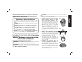
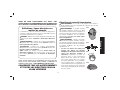
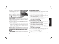
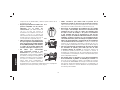
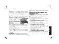
• Actuating tool may result in flying
FIG. A
FIG. B
FIG. C
FIG. D
debris, collation material, or dust
which could harm operator’s eyes.
The operator and all those persons in the
general area should wear safety glasses
with permanently attached side shields.
Approved safety glasses are imprinted
with the characters “Z87.1”. It is the
employer’s responsibility to enforce the
use of eye protection equipment by the
tool operator and other people in the work
area. (Fig. A)
• Always wear appropriate personal
hearing and other protection during
use. Under some conditions and duration
of use, noise from this product may
contribute to hearing loss. (Fig. A)
• Use only clean, dry, regulated air.
Conden sation from an air compressor can
rust and damage the internal workings of
the tool. (Fig. B)
• Regulate air pressure. Use air
pressure compatible with ratings on
the nameplate of the tool. (Not to
exceed 120 psi, 8.3 bar) Do not connect
the tool to a compressor rated at over
200psi. The tool operating pressure must
never exceed 200 psi even in the event of
regulator failure. (Fig. C)
English
1

• Only use air hose that is rated for a maximum working
pressure of at least 150 PSI (10.3 BAR) or 150% of the
maximum system pressure, which ever is greater. (Fig. D)
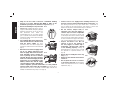
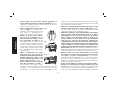
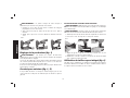
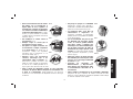
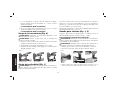
• Do not use bottled gases to power this
FIG. E
FIG. F
FIG. G
tool. Bottled compressed gases such as
oxygen, carbon dioxide, nitrogen, hydrogen,
propane, acetylene or air are not for use
with pneumatic tools. Never use
combustible gases or any other reactive
gas as a power source for this tool. Danger
of explosion and/or serious personal injury
may result. (Fig. E)
• Use couplings that relieve all pressure
from the tool when it is disconnected
from the power supply. Use hose
connectors that shut off air supply from
compressor when the tool is disconnected.
(Fig. F)
• Disconnect tool from air supply when
not in use. Always disconnect tool
from air supply and remove fasteners
from magazine before leaving the
area or passing the tool to another
operator. Do not carry tool to another
work area in which changing location
involves the use of scaffoldings, stairs,
ladders, and the like, with air supply
connected. Do not make adjustments,
remove magazine, perform maintenance or clear jammed
fasteners while connected to the air supply. If the contact trip is
adjusted when the tool is connected to the air supply and nails are
loaded, accidental discharge may occur. (Fig. G)
• Connect tool to air supply before loading fasteners, to
prevent a fastener from being fired during connection. The
tool driving mechanism may cycle when tool is connected to
the air supply. Do not load fasteners with trigger or contact trip
depressed, to prevent unintentional firing of a fastener.
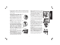
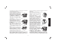
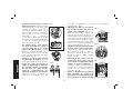
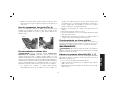
• Do not remove, tamper with, or
FIG. H
FIG. I
FIG. J
otherwise cause the tool, trigger, or
contact trip to become inoperable.
Do not tape or tie trigger or contact trip
in the ON position. Do not remove spring
from contact trip. Make daily inspections
for free movement of trigger and contact
trip. Uncontrolled discharge could result.
• Inspect tool before use. Do not
operate a tool if any portion of
the tool, trigger, or contact trip is
inoperable, disconnected, altered,
or not working properly. Leaking air,
damaged parts or missing parts should
be repaired or replaced before use.
(Fig.H)
• Do not alter or modify the tool in any
way. (Fig. I)
• Always assume that the tool contains
fasteners.
• Do not point the tool at co-workers
or yourself at any time. No horseplay!
Work safe! Respect the tool as a working
implement. (Fig. J)
English
2

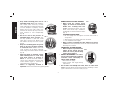
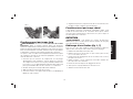
• Keep bystanders, children, and visitors away while operating
a power tool. Distractions can cause you to lose control. When
tool is not in use, it should be locked in a safe place, out of the
reach of children.
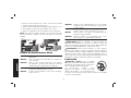
• Remove finger from trigger when
not driving fasteners. Never carry
tool with finger on trigger. Accidental
discharge could result. Using the trigger
lock-off will prevent accidental discharge.
• Do not overreach. Maintain proper
footing and balance at all times. Loss of
balance may cause cause personal injury.
(Fig. K)
• Make sure hose is free of obstructions
or snags. Entangled or snarled hoses
can cause loss of balance or footing.
• Use the tool only for its intended use.
Do not discharge fasteners into open
air, concrete, stone, extremely hard
woods, knots or any material too
hard for the fastener to penetrate.
Do not use the body of the tool or
top cap as a hammer. Discharged
fasteners may follow unexpected path
and cause injury. (Fig. L)
• Always keep fingers clear of contact
trip to prevent injury from inadvertent
release of nails. (Fig. M)
• Refer to the Maintenance and Repairs
sections for detailed information on
the proper maintenance of the tool
• Always operate the tool in a clean,
lighted area. Be sure the work surface
is clear of any debris and be careful not
to lose footing when working in elevated
environments such as rooftops.
• Do not drive fasteners near edge
of material. The workpiece may split
causing the fastener to ricochet, injuring
you or a co-worker. Be aware that the nail
may follow the grain of the wood (shiner),
causing it to protrude unexpectedly from
the side of the work material. Drive the nail
perpendicular to the grain to reduce risk
of injury. (Fig. N)
• Do not drive nails onto the heads
of other fasteners or with the tool
at too steep an angle. Personal injury
from strong recoil, jammed fasteners, or
ricocheted nails may result. (Fig. O)
• Be aware of material thickness when
using the nailer. A protruding nail may
cause injury.
• Be aware that when the tool is being
utilized at pressures on the high end
of its operating range, nails can be
driven completely through thin or
very soft work material. Make sure
the pressure in the compressor is set so
that nails are set into the material and not
pushed completely through. (Fig. P)
FIG. K
FIG. L
FIG. M
FPO
FIG. P
FIG. N
FIG. O
English
3

• Keep hands and body parts clear of
FIG. Q
FIG. R
FIG. S
immediate work area. Hold workpiece
with clamps when necessary to keep
hands and body out of potential harm. Be
sure the workpiece is properly secured
before pressing the nailer against the
material. The contact trip may cause the
work material to shift unexpectedly.
(Fig.Q)
• Do not use tool in the presence of
flammable dust, gases or fumes. The
tool may produce a spark that could
ignite gases causing a fire. Driving a nail
into another nail may also cause a spark.
(Fig.R)
• Keep face and body parts away from
back of the tool cap when working
in restricted areas. Sudden recoil can
result in impact to the body, especially
when nailing into hard or dense material.
(Fig. S)
• Grip tool firmly to maintain control
while allowing tool to recoil away
from work surface as fastener is
driven. In “Contact Actuation Mode” if
contact trip is allowed to recontact work
surface before trigger is released an
unwanted fastener will be fired.
• Choice of triggering method is
important. Check the manual for triggering options.
BUMP/CONTACT ACTION TRIGGER
• When using the contact action
FIG. T
trigger, be careful of unin tentional
double fires resulting from tool
recoil. Unwanted fasteners may be
driven if the contact trip is allowed to
accidentally re-contact the work surface.
(Fig. T)
TO AVOID DOUBLE FIRES:
• Do not engage the tool against the work surface with a
strong force.
• Allow the tool to recoil fully after each actuation.
• Use sequential action trigger.
• When “contact” actuating the nailer, always keep tool in
control. Inaccurate placement of tool can result in misdirected
discharge of a fastener.
SEQUENTIAL ACTION TRIGGER
• When using the sequential action
FIG. U
trigger, do not actuate the tool
unless the tool is placed firmly
against the workpiece.
• DEPTH ADJUSTMENT: To reduce
risk of serious injury from accidental
actuation when attempting to
adjust depth, ALWAYS;
• Disconnect air supply
• Avoid contact with trigger during
adjustments
• Do not drive nails blindly into walls, floors or other work
areas. Fasteners driven into live electrical wires, plumbing, or other
types of obstructions can result in injury. (Fig.U)
English
4

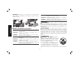
• Stay alert, watch what you are doing and use common
sense when operating a power tool. Do not use tool while
tired or under the influence of drugs, alcohol, or medication.
A moment of inattention while operating power tools may result in
serious personal injury.
WARNING: Some dust created by power sanding, sawing,
grinding, drilling, and other construction activities contains chemicals
known to the State of California to cause cancer, birth defects or other
reproductive harm. Some examples of these chemicals are:
• lead from lead-based paints,
• crystalline silica from bricks and cement and other masonry
products, and
• arsenic and chromium from chemically-treated lumber.
Your risk from these exposures varies, depending on how often you
do this type of work. To reduce your exposure to these chemicals:
work in a well ventilated area, and work with approved safety
equipment, such as those dust masks that are specially designed to
filter out microscopic particles.
WARNING: ALWAYS USE SAFETY GLASSES. Everyday
eyeglasses are NOT safety glasses. Also use face or dust mask
if operation is dusty. ALWAYS WEAR CERTIFIED SAFETY
EQUIPMENT:
• ANSI Z87.1 eye protection (CAN/CSA/Z94.3),
• ANSI S12.6 (S3.19) hearing protection,
• NIOSH/OSHA/MSHA respiratory protection.
SAVE ALL WARNINGS AND INSTRUCTIONS
FOR FUTURE REFERENCE
Tool Specifi cations
MODEL DWFP71917
DESCRIPTION 16 Gauge Finish Nailer
ENGINE TYPE Oil-Free
OPERATION PRESSURE
RANGE
70 – 120 psig (4.9 – 8.43kg/cm
2
)
MAXIMUM OPERATION
PRESSURE
120 psi (8.43 kg/cm
2
)
AIR CONSUMPTION AT A
RATE OF 60 FASTENERS
PER MINUTE*
2.0 cfm (56.6 lt/min @
80 psi (5.6 kg/cm
2
)
FASTENER GAUGE 16 Gauge
FASTENER RANGE 1–1/4" to 2–1/2" (32mm – 64mm)
MAGAZINE CAPACITY up to 100 Nails
LENGTH 12-1/2" (316.6mm)
WIDTH 3-1/3" (84.1mm)
HEIGHT 11-5/16" (288.5mm)
WEIGHT 3.9lbs (1.7kg)
* The DWFP71917 requires 2.0 cubic feet per minute or cfm (56.6liters
per minute or lt/min) of free air at 80 psi (5.6 kg/cm
2
) to operate at a
rate of 60 fasteners per minute. To determine the appropriately sized
air compressor, take the actual rate at which the tool will be run and
compare the required cfm (lt/min) to the compressors free air delivery
(cfm/ lt/min) at 80 psi (5.6 kg/cm
2
).
English
5

For example, if your fastener usage averages 30 fasteners per minute,
you need 50% of the tools cfm required to operate the tool at the
rate of 60 fasteners per minute. In this case, be sure that your air
compressor can deliver a minimum of 1.0 cfm. (28.3 lt/min) at 80psi
(5.6 kg/cm
2
) for optimum performance.
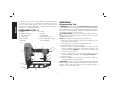
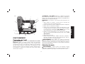
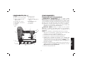
COMPONENTS (FIG. 1)
A. Trigger
B. Trigger mode selector
C. Jam clearing latch
D. Contact trip
E. No-mar pad
F. Magazine
G. Pusher
H. Air inlet
I. Rear exhaust
J. Adjustable belt hook
K. Depth adjustment wheel
L. Pencil sharpener
FIG. 1
H
A
D
I
F
B
C
G
J
E
K
L
OPERATION
Preparing the Tool
WARNING: Read the section titled Important Safety Instructions
at the beginning of this manual. Always wear eye and ear protection
when operating this tool. Keep the nailer pointed away from yourself
and others. For safe operation, complete the following procedures
and checks before each use of the nailer.
CAUTION: NEVER spray or in any other way apply lubricants or
cleaning solvents inside the tool. This can seriously affect the life and
performance of the tool.
NOTE: These nailers are designed to be used without oil.
1. Before you use the nailer, be sure that the compressor tanks
have been properly drained.
2. Wear proper eye, hearing and respiratory protection.
3. Remove all fasteners from the magazine.
4. Check for smooth and proper operation of contact trip and
pusher assemblies. Do not use tool if either assembly is not
functioning properly. NEVER use a tool that has the contact trip
restrained in the up position.
5. Check air supply. Ensure that air pressure does not exceed
recommended operating limits, refer to Tool Specifications.
6. Connect air hose.
7. Check for audible leaks around valves and gaskets. Never use
a tool that leaks or has damaged parts.
WARNING: To reduce the risk of personal injury, disconnect tool
from air supply before performing maintenance, clearing a jammed
fastener, leaving work area, moving tool to another location or
handing the tool to another person.
English
6

Mode Selection
WARNING: Always wear proper eye [ANSI Z87.1 (CAN/CSA
Z94.3)] and hearing protection [ANSI S12.6 (S3.19)] when operating
this tool.
WARNING: Keep fingers AWAY from trigger when not driving
fasteners to avoid accidental firing. NEVER carry tool with finger on
trigger. In contact mode tool will fire a fastener if safety is bumped
while trigger is depressed.
The DWFP71917 features a selectable trigger system that allows the
user to choose between the following modes of operation
Sequential Trip
The Sequential Trip requires the operator to hold the tool against
the work before pulling the trigger. This makes accurate fastener
placement easier. The Sequential Trip allows exact fastener location
without the possibility if driving a second fastener on recoil as
described under Contact Trip. The Sequential Trip Tool has a
positive advantage because it will not accidentally drive a fastener
if the tool is contacted against the work surface - or anything else -
while the operator is holding the trigger pulled.
Contact Trip
The common operation procedure on “Contact Trip” tools is for the
operator to contact the work surface to actuate the trip mechanism
while keeping the trigger pulled, thus driving a fastener each time the
work surface is contacted. This will allow rapid fastener placement
on many jobs. All pneumatic tools are subject to recoil when
driving fasteners. The tool may bounce, releasing the trip, and if
unintentionally allowed to re-contact the work surface with the trigger
still actuated (finger still holding the trigger pulled) an unwanted
second fastener will be driven.
TO CHANGE OPERATING MODES (FIG. 1–3)
WARNING: Disconnect air line from tool and remove fasteners
from magazine before making adjustments or personal injury may
result.
SEQUENTIAL TRIP ACTION
Use sequential action for intermittent nailing where very careful and
accurate placement is desired.
To operate the nailer in sequential action mode:
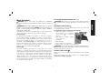
1. Rotate the trigger mode selector
FIG. 2
(B) clockwise to the sequential
action position
, as shown in
Figure 2.
2. Fully depress nosepiece against
the work surface.
3. Pull trigger.
4. Release trigger.
5. Lift nosepiece off work surface.
6. Repeat steps 2 through 4 for next application.
WARNING: The contact trip needs to be depressed followed by a
trigger pull for each fastener followed by a release of both the contact
trip and trigger after each fastener.
CONTACT TRIP ACTION
Bump/contact action is intended for rapid nailing on flat, stationary
surfaces.
When using bump action, two methods are available: place
actuation and bump actuation.
English
7

Rotate the trigger mode selector (B)
FIG. 3
counterclockwise to the contact action
position
, as shown in Figure 3.
To operate the tool using the
PLACE ACTUATION method:
WARNING: A fastener will fire each
time the trigger is depressed as long
as the contact trip remains depressed.
1. Depress the contact trip against
the work surface.
2. Depress the trigger.
To operate the tool using the BUMP ACTUATION method:
1. Depress the trigger.
2. Push the contact trip against the work surface. As long as the
trigger is depressed, the tool will fire a fastener every time the
contact trip is depressed. This allows the user to drive multiple
fasteners in sequence.
WARNING: Do not keep trigger depressed when tool is not in use.
Keep the contact trip lock-off engaged in the locked position when
the tool is not in use.
Tool Operation Check (Fig.1)
WARNING: If the tool is dropped or you suspect tool damage
perform tool operation check.
WARNING: Remove all fasteners from tool before performing tool
operation check.
SEQUENTIAL TRIP ACTION
A. Press the contact trip against the work surface, without touching
the trigger.
THE TOOL MUST NOT CYCLE.
B. Hold the tool off the work surface and pull the trigger.
THE TOOL MUST NOT CYCLE.
C. Pull the trigger and press the contact trip against the work
surface.
THE TOOL MUST NOT CYCLE.
D. With finger off the trigger, press the contact trip against the work
surface. Pull the trigger.
THE TOOL MUST CYCLE.
CONTACT TRIP ACTION
A. With finger off the trigger, press the contact trip against the work
surface.
THE TOOL MUST NOT CYCLE.
B. Hold the tool off the work surface, and pull the trigger.
THE TOOL MUST NOT CYCLE.
C. With the tool off the work surface, pull the trigger. Press the
contact trip against the work surface.
THE TOOL MUST CYCLE.
D. Without touching the trigger, press the contact trip against the
work surface, then pull the trigger.
THE TOOL MUST CYCLE.
Loading the Tool (Fig. 4)
WARNING: Keep tool pointed in a safe direction when loading
nails.
WARNING: Never load nails with the contact trip or trigger
activated.
1. Load nails through the slot in the rear of the magazine and past
retaining clip.
English
8

2. Pull pusher back behind nail stick and release.
3. Ensure magazine pusher is behind the last nail stick.
FIG. 4
Depth Setting (Fig. 1)
WARNING: Disconnect air line from tool and remove fasteners
from magazine before making adjustments or personal injury may
result.
The fastener depth control adjustment feature provides control of
the nail drive depth from flush with or just above the work surface
to shallow or deep countersink.
Rotate depth control adjustment wheel (K) to give the desired depth
of drive.
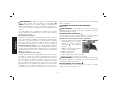
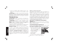
Belt Hook (Fig. 1, 5)
The belt hook (J) can be changed to either side of the tool to
accommodate left- or right-handed users.
INSTALLING THE BELT HOOK
WARNING: Disconnect air line from tool and remove fasteners
from magazine before making adjustments or before attempting any
assembly or disassembly.
WARNING: Always remove the belt hook from the tool when
selecting Contact Trip Mode.
1. Assure that the sequential trip mode is selected.
2. Squeeze the sides of the belt hook body.
FIG. 5
J
3. Align the post on the belt hook body with the alignment hole and
push into position.
4. Release the sides of the belt hook body and check to ensure that
the belt hook is locked in position.
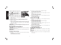
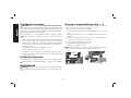
Using The Integrated Pencil Sharpener
(Fig. 6)
A standard pencil sharpener (L) is integrated into the belt hook for
the operator’s convenience. To sharpen a pencil, insert any standard
pencil into the hole and rotate the pencil to the right (clockwise)to
sharpen.
FIG. 6
L
English
9

Cold Weather Operation
WARNING: Read the section titled Important Safety Instructions
at the beginning of this manual. Always wear eye and ear protection
when operating this tool. Keep the nailer pointed away from yourself
and others. For safe operation, complete the following procedures
and checks before each use of the nailer.
When operating tools at temperatures below freezing, complete
preparation procedures outlined above and follow the directions
below.
1. Make sure compressor tanks have been properly drained prior
to use. Always drain the compressor tanks at least once daily
while using the nailer. This is especially important in cold weather
because any moisture in the air in the tanks will condense in the
cold temperature.
2. Keep the tool as warm as possible prior to use.
3. Lower air pressure to 80 psi or less.
4. Actuate the tool 5 or 6 times into scrap lumber to lubricate o-rings.
5. Turn pressure up to operating level (not to exceed 120 psi) and
use tool as normal.
Hot Weather Operation
Tool should operate normally. However, keep tool out of direct sunlight
as excessive heat can damage bumpers, o-rings and other rubber
parts.
MAINTENANCE
WARNING: Disconnect air line from tool and remove fasteners
from magazine before making adjustments or personal injury may
result.
Clearing a Jammed Fastener (Fig. 1, 7)
If a fastener becomes jammed in the nosepiece, keep the tool pointed
away from you and follow these instructions to clear:
1. Disconnect the tool from the air supply.
2. Release the pusher (G) so it is no longer applying force to the nail
sticks.
3. Open the jam clearing nose door by pulling down and then up on
the latch.
4. Remove the jammed fastener. In certain circumstances, pliers
may be required to remove the fastener.
5. Close the jam clearing nose door latch.
6. Pull nail pusher back behind nail sticks.
7. Perform tool operation check.
NOTE: Should fasteners continue to jam frequently in nosepiece,
have tool serviced by an authorized D
EWALT service center.
FIG. 7
English
10

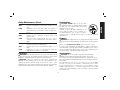
Daily Maintenance Chart
ACTION Drain compressor tanks and hoses daily
WHY Prevents accumulation of moisture in compressor and
nailer
HOW Open petcocks or other drain valves on compressor
tanks. Allow any accumulated water to drain from
hoses
ACTION Clean magazine, pusher, and contact trip mechanism
WHY Permits smooth operation, reduces wear, and
prevents jams
HOW Blow clean with compressed air. The use of oils or
solvents is not recommended as they tend to attract
debris
ACTION Before each use, check to ensure all screws, nuts and
fasteners are tight and undamaged
WHY Prevents jams, leaks and premature failure of tool
parts
HOW Tighten loose screws or other fasteners using the
appropriate hex wrench or screwdriver
Cleaning
WARNING: Blow dirt and dust out of all air vents with clean, dry air
at least once a week. To minimize the risk of eye injury, always wear
ANSI Z87.1 approved eye protection when performing this.
WARNING: Never use solvents or other harsh chemicals for
cleaning the non-metallic parts of the tool. These chemicals may
weaken the plastic materials used in these parts. Use a cloth
dampened only with water and mild soap. Never let any liquid get
inside the tool; never immerse any part of the tool into a liquid.
Lubrication
CAUTION: NEVER spray or in any other
way apply lubricants or cleaning solvents inside
the tool. This can seriously affect the life and
performance of the tool.
D
EWALT tools are properly lubricated at the
factory and are ready for use. However, it is
recommended that, once a year, you take or
send the tool to a certified service center for a thorough cleaning
and inspection.
Repairs
WARNING: To reduce the risk of serious personal injury, remove
nails from magazine before making any adjustments or servicing this
tool.
Refer to the Troubleshooting Guide at the end of this section.
To assure product SAFETY and RELIABILITY, repairs, maintenance
and adjustment should be performed by a D
EWALT factory service
center, a D
EWALT authorized service center or other qualified service
personnel. Always use identical replacement parts.
Accessories
WARNING: Since accessories, other than those offered by
D
EWALT, have not been tested with this product, use of such
accessories with this tool could be hazardous. To reduce the risk of
injury, only D
EWALT, recommended accessories should be used with
this product.
Recommended accessories for use with your tool are available
at extra cost from your local dealer or authorized service center.
If you need assistance in locating any accessory, please contact
DEWALT Industrial Tool Co., 701 East Joppa Road, Towson, MD
21286, call 1-800-4-DEWALT (1-800-433-9258) or visit our website
www.dewalt.com.
English
11

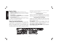
Register Online
Thank you for your purchase. Register your product now for:
• WARRANTY SERVICE: Registering your product will help you
obtain more efficient warranty service in case there is a problem
with your product.
• CONFIRMATION OF OWNERSHIP: In case of an insurance
loss, such as fire, flood or theft, your registration of ownership will
serve as your proof of purchase.
• FOR YOUR SAFETY: Registering your product will allow us to
contact you in the unlikely event a safety notification is required
under the Consumer Product Safety Act.
Register online at www.dewalt.com/register.
Seven Year Limited Warranty
DEWALT will repair, without charge, any defects due to faulty materials
or workmanship for seven years from the date of purchase. This
warranty does not cover part failure due to normal wear or tool
abuse. For further detail of warranty coverage and warranty repair
information, visit www.dewalt.com or call 1-800-4-D
EWALT (1-800-
433-9258). This warranty does not apply to accessories or damage
caused where repairs have been made or attempted by others. This
warranty gives you specific legal rights and you may have other rights
which vary in certain states or provinces.
In addition to the warranty, D
EWALT tools are covered by our:
1 YEAR FREE SERVICE
D
EWALT will maintain the tool and replace worn parts caused by
normal use, for free, any time during the first year after purchase.
Nailer wear items, such as o-rings and driver blades, are not covered.
90 DAY MONEY BACK GUARANTEE
If you are not completely satisfied with the performance of your
D
EWALT Power Tool, Laser, or Nailer for any reason, you can return
it within 90 days from the date of purchase with a receipt for a full
refund – no questions asked.
LATIN AMERICA: This warranty does not apply to products sold
in Latin America. For products sold in Latin America, see country
specific warranty information contained in the packaging, call the
local company or see website for warranty information.
FREE WARNING LABEL REPLACEMENT: If your warning labels
become illegible or are missing, call 1-800-4-D
EWALT (1-800-433-
9258) for a free replacement.
English
12

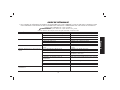
TROUBLESHOOTING GUIDE
MANY COMMON PROBLEMS CAN BE SOLVED EASILY BY UTILIZING THE CHART BELOW.
FOR MORE SERIOUS OR PERSISTENT PROBLEMS, CONTACT A D
EWALT SERVICE CENTER OR CALL 1-(800)-4-DEWALT.
WARNING: To reduce the risk of serious personal injury, remove
fasteners from magazine before making any adjustments or servicing this tool.
SYMPTOM CAUSE FIX
Trigger valve housing leaks air O-ring cut or cracked Replace O-ring
Trigger valve stem leaks air O-ring/seals cut or cracked Replace trigger valve assembly
Frame/nose leaks air O-ring or gasket is cut or cracked Replace O-ring or gasket
Bumper cracked/worn Replace bumper
Frame/cap leaks air Damaged gasket or seal Replace gasket or seal
Cracked/worn head valve Replace head valve
Loose cap screws Tighten and recheck
Failure to cycle Air supply restriction Check air supply equipment
Worn head valve Replace head valve
Broken cylinder cap spring Replace cylinder cap spring
Head valve stuck in cap Disassemble / Check
Failure to complete cycle Debris in nose, door, contact arm area Clean nose, door, contact arm area
Lack of power; slow to cycle Broken cylinder cap spring Replace cap spring
Rings/seals cut or cracked Replace rings/seals
Exhaust blocked Check bumper, head valve spring
Trigger assembly worn/leaks Replace trigger assembly
Dirt/tar build up on driver Disassemble nose/driver to clean
Cylinder sleeve not seated correctly on bottom bumper Disassemble to correct
Air pressure too low Check air supply equipment
Clogged air filter Clean or replace air filter
English
13

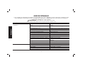
TROUBLESHOOTING GUIDE
MANY COMMON PROBLEMS CAN BE SOLVED EASILY BY UTILIZING THE CHART BELOW.
FOR MORE SERIOUS OR PERSISTENT PROBLEMS, CONTACT A D
EWALT SERVICE CENTER OR CALL 1-(800)-4-DEWALT.
WARNING: To reduce the risk of serious personal injury, remove
fasteners from magazine before making any adjustments or servicing this tool.
SYMPTOM CAUSE FIX
Skipping fasteners; intermittent
feed
Worn bumper Replace bumper
Debris in nose, door, contact arm area Clean nose, door, contact arm area
Air restriction/inadequate air flow through quick disconnect
socket and plug
Replace quick disconnect fittings
Worn piston ring Replace ring, check driver
Damaged pusher spring Replace spring
Low air pressure Check air supply system to tool
Loose magazine nose screws Tighten all screws
Fasteners too short for tool Use only recommended fasteners
Bent fasteners Discontinue using these fasteners
Wrong size fasteners Use only recommended fasteners
Leaking head cap gasket Tighten screws/replace gasket
Trigger valve O-ring cut/worn Replace O-ring
Broken/chipped driver Replace driver (check piston ring)
Dry/dirty magazine Clean
Worn magazine Replace magazine
Clogged air filter Clean or replace air filter
Fasteners jam in tool Driver channel worn Replace nose/check door
Wrong size fasteners Use only recommended fasteners
Bent fasteners Discontinue using these fasteners
Loose magazine/nose screws Tighten all screws
Broken/chipped driver Replace driver
English
14
Page is loading ...
Page is loading ...
Page is loading ...
Page is loading ...
Page is loading ...
Page is loading ...
Page is loading ...
Page is loading ...
Page is loading ...
Page is loading ...
Page is loading ...
Page is loading ...
Page is loading ...
Page is loading ...
Page is loading ...
Page is loading ...
Page is loading ...
Page is loading ...
Page is loading ...
Page is loading ...
Page is loading ...
Page is loading ...
Page is loading ...
Page is loading ...
Page is loading ...
Page is loading ...
Page is loading ...
Page is loading ...
Page is loading ...
Page is loading ...
Page is loading ...
Page is loading ...
Page is loading ...
Page is loading ...
Page is loading ...

DEWALT Industrial Tool Co., 701 East Joppa Road, Towson, MD 21286
(NOV14) Part No. 9R209199 DWFP71917 Copyright © 2014 D
EWALT
The following are trademarks for one or more D
EWALT power tools: the yellow and black color scheme; the “D” shaped air intake grill; the array
of pyramids on the handgrip; the kit box configuration; and the array of lozenge-shaped humps on the surface of the tool.
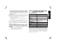
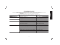
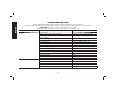
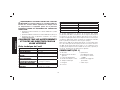
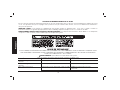
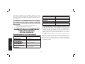
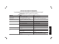
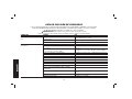
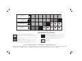
Compressor will be sufficient for tools at all production rates.
Le compresseur sera suffisant pour les outils à tous les taux de production.
El compresor será suficiente para las herramientas a cualquier velocidad de
trabajo
Compressor will be sufficient at slow or moderate production rates, but may
have difficulty at very rapid rates.
Le compresseur est suffisant pour les cadences de production lentes ou
modérées, mais son rendement pourrait être insuffisant pour les cadences
très rapides.
El compresor será suficiente a velocidades de trabajo bajas o moderadas, pero
puede tener dificultades en velocidades muy rápidas.
8+
NUMBER OF TOOLS CONNECTED TO COMPRESSOR
NOMBRE D’OUTILS RACCORDÉS AU COMPRESSEUR
NÚMERO DE HERRAMIENTAS CONECTADAS AL COMPRESOR
1 2 3 4 5
6
7
Portable Handcarry 3.2 - 4 CFM
Portable à la main 3,2 à 4 pieds cubes
par minute
Transportable 3.2 - 4 CFM
5.5 HP Gas/2 HP Elec. 8 - 9 CFM
5.5 HP Essence/ 2 CH Élec. 8 à 9 pieds
cubes par minute
5.5 CV Gas/ 2 CV Elec. 8 -9 CFM
8 HP Gas 14 - 16 CFM
8 CH Essence 14 à 16 pieds cubes par
minute
8 CV Gas 14 -16 CFM
Industrial 23+ CFM
Industriel 23 pieds cubes par minute et +
Industrial 23+ CFM
Compressor will be adequate only when tools are utilized at slow production
rates. (punch-out or occasional use)
Le compresseur est adéquat uniquement quand les outils sont utilisés à des
cadences de production lentes (perforation ou utilisation occasionnelle).
El compresor sólo será adecuado cuando las herramientas se utilicen en
velocidades de trabajo lentas (perforación o uso ocasional).
Not Recommended
Non recommandé
No recomendado
-
 1
1
-
 2
2
-
 3
3
-
 4
4
-
 5
5
-
 6
6
-
 7
7
-
 8
8
-
 9
9
-
 10
10
-
 11
11
-
 12
12
-
 13
13
-
 14
14
-
 15
15
-
 16
16
-
 17
17
-
 18
18
-
 19
19
-
 20
20
-
 21
21
-
 22
22
-
 23
23
-
 24
24
-
 25
25
-
 26
26
-
 27
27
-
 28
28
-
 29
29
-
 30
30
-
 31
31
-
 32
32
-
 33
33
-
 34
34
-
 35
35
-
 36
36
-
 37
37
-
 38
38
-
 39
39
-
 40
40
-
 41
41
-
 42
42
-
 43
43
-
 44
44
-
 45
45
-
 46
46
-
 47
47
-
 48
48
-
 49
49
-
 50
50
-
 51
51
-
 52
52


Ask a question and I''ll find the answer in the document
Finding information in a document is now easier with AI
in other languages
- français: DeWalt DWFP71917 Manuel utilisateur
- español: DeWalt DWFP71917 Manual de usuario
Related papers
Other documents
-
Stanley FMC792 User manual
-
Porter-Cable DA250CC2002 User guide
-
Porter-Cable DA250C User manual
-
Ryobi YG250FS User guide
-
-
-
-
-
Porter Cable NS150C User manual
-