Page is loading ...

Gas Fired Direct Vented Room Heater
Model #: UF-0500
UF-0510
INSTALLATION AND
OPERATING MANUAL
This appliance may be installed in an aftermarket permanently located, manufactured home (USA only)
or mobile home, where not prohibited by local codes.
This appliance is only for use with the type of gas indicated on the rating plate. This appliance is not
convertible for use with other gases, unless a certified kit is used.
June 2015 Rev 1-01
Tested and listed by
Inspiration
Serial Numbers: 600001 - forward
Archgard Industries
7116 Beatty Drive, Mission, B.C.
Canada, V2V-6B4
❖ Do not store or use gasoline or other flammable vapors and liquids in the vicinity of this
or any other appliance.
WHAT TO DO IF YOU SMELL GAS:
❖ Do not try to light any appliance.
❖ Do not touch any electrical switch; do not use any phone in your building.
❖ Leave your building immediately
❖ Immediately call your gas supplier from a neighbor’s phone. Follow the gas supplier’s
instructions.
❖ If you cannot reach your gas supplier, call the fire department.
Installation and service must be performed by a qualified installer, service
agency or the gas supplier.
WARNING:
FIRE OR EXPLOSION HAZARD.
Failure to follow safety warnings exactly could result in serious injury, death or
property damage
INSTALLER: Leave this manual with the appliance.
CONSUMER: Retain this manual for future reference.
200-0500

2
TABLE OF CONTENTS
State of Massachusetts Requirements 3
Safety Information 4
Rating Plate 5
Specifications
Fireplace Dimensions / Clearances 6 - 7
Relocating Valve and Module 7
Leveling the unit 8
Minimum Opening Dimensions / Sealing the vent 8-9
Factory Built Opening requirements 10
Mantle Clearances 11
Gas-line Connections / High Altitude Installation 12
Pressure Testing 13
Electrical Connections / Light Kit Installation 14
Wiring Diagram - Control Module 15
Venting / Vent Restrictor Installation 16 - 18
Logs and Placement 19 - 21
Contemporary Burner Set-up 22-23
Glass Door Removal & Replacement 24
Safety Barrier Installation 25
Surround Installation 26
Final Installation Check 27
Control System Components 28
System Operation 29 - 32
SIT Pilot Ignition Sequence Flowchart 33
SIT Burner Ignition Sequence Flowchart 34
Lighting & Shutdown
First Fire 35
Initial Operation 36
Lighting Instructions 37
Finalizing the Installation
Flame Appearance 38
Checking & Adjusting the pilot 39
Maintenance & Cleaning 40
Adjusting the Primary Air 40
Replacing the Comfort Fan 40
Troubleshooting 41 - 42
Frequently asked questions 43
Conversion Kit Instructions 44 - 45
Replacement Parts List 46
Limited 10 YR Warranty 47
Limited Lifetime Warranty 48

5.08: Modifications to NFPA-54, Chapter 10
(2) Revise 10.8.3 by adding the following additional requirements:
(a) For all side wall horizontally vented gas fueled equipment installed in every dwelling, building or structure used in whole or in part
for residential purposes, including those owned or operated by the Commonwealth and where the side wall exhaust vent termination is
less than seven (7) feet above finished grade in the area of the venting, including but not limited to decks and porches, the following
requirements shall be satisfied:
1. INSTALLATION OF CARBON MONOXIDE DETECTORS. At the time of installation of the side wall horizontal vented gas fueled
equipment, the installing plumber or gasfitter shall observe that a hard wired carbon monoxide detector with an alarm and battery back-
up is installed on the floor level where the gas equipment is to be installed. In addition, the installing plumber or gasfitter shall observe
that a battery operated or hard wired carbon monoxide detector with an alarm is installed on each additional level of the dwelling, build-
ing or structure served by the side wall horizontal vented gas fueled equipment. It shall be the responsibility of the property owner to
secure the services of qualified licensed professionals for the installation of hard wired carbon monoxide detectors
a. In the event that the side wall horizontally vented gas fueled equipment is installed in a crawl space or an attic, the hard wired carbon
monoxide detector with alarm and battery back-up may be installed on the next adjacent floor level.
b. In the event that the requirements of this subdivision can not be met at the time of completion of installation, the owner shall have a
period of thirty (30) days to comply with the above requirements; provided, however, that during said thirty (30) day period, a battery
operated carbon monoxide detector with an alarm shall be installed.
2. APPROVED CARBON MONOXIDE DETECTORS. Each carbon monoxide detector as required in accordance with the above provi-
sions shall comply with NFPA 720 and be ANSI/UL 2034 listed and IAS certified.
3. SIGNAGE. A metal or plastic identification plate shall be permanently mounted to the exterior of the building at a minimum height of
eight (8) feet above grade directly in line with the exhaust vent terminal for the horizontally vented gas fueled heating appliance or
equipment. The sign shall read, in print size no less than one-half (1/2) inch in size, "GAS VENT DIRECTLY BELOW. KEEP
CLEAR OF ALL OBSTRUCTIONS".
4. INSPECTION. The state or local gas inspector of the side wall horizontally vented gas fueled equipment shall not approve the instal-
lation unless, upon inspection, the inspector observes carbon monoxide detectors and signage installed in accordance with the provisions
of 248 CMR 5.08(2)(a)1 through 4.
(b) EXEMPTIONS: The following equipment is exempt from 248 CMR 5.08(2)(a)1 through 4:
1. The equipment listed in Chapter 10 entitled "Equipment Not Required To Be Vented" in the most current edition of NFPA 54 as
adopted by the Board; and
2. Product Approved side wall horizontally vented gas fueled equipment installed in a room or structure separate from the dwelling,
building or structure used in whole or in part for residential purposes.
(c) MANUFACTURER REQUIREMENTS - GAS EQUIPMENT VENTING SYSTEM PROVIDED. When the manufacturer of Prod-
uct Approved side wall horizontally vented gas equipment provides a venting system design or venting system components with the
equipment, the instructions provided by the manufacturer for installation of the equipment and the venting system shall include:
1. Detailed instructions for the installation of the venting system design or the venting system components; and
2. A complete parts list for the venting system design or venting system.
(d) MANUFACTURER REQUIREMENTS - GAS EQUIPMENT VENTING SYSTEM NOT PROVIDED. When the manufacturer of a
Product Approved side wall horizontally vented gas fueled equipment does not provide the parts for venting the flue gases, but identifies
"special venting systems", the following requirements shall be satisfied by the manufacturer:
1. The referenced "special venting system" instructions shall be included with the appliance or equipment installation instructions; and
2. The "special venting systems" shall be Product Approved by the Board, and the instructions for that system shall include a parts list
and detailed installation instructions.
(e) A copy of all installation instructions for all Product Approved side wall horizontally vented gas fueled equipment, all venting in-
structions, all parts lists for venting instructions, and/or all venting design instructions shall remain with the appliance or equipment at
the completion of the installation.
STATE OF MASSACHUSETTS REQUIREMENTS
For the State of Massachusetts, installation and repair must be done by a plumber or gasfitter li-
censed in the Commonwealth of Massachusetts.
For the State of Massachusetts, flexible connectors shall not exceed 36 inches in length.
The State of Massachusetts requires the installation of a carbon monoxide alarm in accordance
with NFPA 720 and a CO alarm with battery back up in the same room where the gas appliance is
installed.
For the State of Massachusetts the appliances individual shut – off must be a t-handle type valve.

4
FOR YOUR SAFETY - Do not install or operate your Inspiration Fireplace without reading and understanding this
manual.
Any installation or operational deviation from this instruction manual voids the warranty and may prove
hazardous.
This appliance must be installed by a qualified gas installer and the installation must conform to the installation
codes.
Provide adequate clearance around air openings. Never obstruct front openings
Provide adequate clearances for proper operation and servicing of the appliance.
This appliance must be properly connected to an approved venting system and must not be connected to a
chimney flue serving a separate solid fuel burning appliance.
Must provide adequate clearance around the intake and exhaust openings
Due to high temperatures, the appliance should be located out of traffic and away from furniture and draperies.
Children and adults should be alerted to the hazards of high surface temperature and stay away to avoid burns or
clothing ignition.
Young children should be carefully supervised when they are in the same room as the appliance. Toddlers,
young children and others may be susceptible to accidental contact burns. A physical barrier is recommended if
there are at risk individuals in the house. To restrict access to a fireplace or stove, install an adjustable safety gate
to keep toddlers, young children and other at risk individuals out of the room and away from hot surfaces.
Clothing or other flammable material should not be placed on or near the appliance.
Do not operate with cracked or broken glass. Be careful not to strike or slam the glass.
Any safety screen or guard removed for servicing an appliance must be replaced prior to operating.
Installation and Repair should be done by a qualified service person. The appliance should be inspected before
use and at least annually by a professional service person. More frequent cleaning may be required due to
excessive lint from carpeting, bedding materials, etc. It is imperative that the control compartments, burners and
circulating air passageways of the appliance are kept clean.
Do not use this appliance if any part has been under water. Immediately call a qualified service technician to
inspect the appliance and to replace any part of the control system and any gas control which has been under
water.
SAFETY INFORMATION
This appliance was listed by LABTEST Certification Inc and complies with:
ANSI Z21.88-2014/CSA 2.33-2014 Vented Gas Fireplace Heaters
CAN/CGA-2.17-M91 Gas-Fired Appliances for Use at High Altitudes
CSA P.4.1-09 testing method for measuring annual fireplace efficiency.
The installation must conform with the local codes or, in the absence of local codes, with the current National Fuel
Gas Code ANSI Z223.1/ NFPA 54 or the Natural Gas and Propane Installation Code, CSA B149.1.
Electrical connections and grounding must conform with local code, or current National Electrical code ANSI/
NFPA No. 70-1987 and in Canada the current Canadian Electrical Code CSA C22.1.

5
RATING PLATE
This appliance must be installed in accordance with local codes, if any; if none, follow the National Fuel Gas Code, ANSI Z223.1/NFPA 54, or
Natural Gas and Propane Installation Codes, CSA B149,1. Electrical connections and grounding must be in accordance with local codes, if any; if
none, follow the current CAN/CSA C22.1 in Canada and ANSI/NFPA 70 in the US. This appliance is certified for installation in a bedroom or a bed
sitting room. This appliance is only for use with the gas indicated on the rating plate and may be installed in an aftermarket, permanently located,
manufactured (mobile) home where not prohibited by local codes. See owner’s manual for details. This appliance is not convertible with other
gases, unless a certified kit is used.
FOR USE WITH GLASS DOOR CERTIFIED WITH THIS APPLIANCE ONLY.
Il faut que cet appareil soit installé selon les codes locaux, s’il y en a; sinon, suivre le CAN/CGA-B149 actuel au Canada et ANSI Z223.1 aux É.-U. Il
faut que le raccordement électrique et la mise à la masse soient en conformité avec les codes locaux, s’il y en a; sinon, suivre le CAN/CSA C22.1
actuel au Canada et ANSI/NFPA 70 aux É.-U. Cet appareil est certifié pour l’installation dans une chambre à coucher ou une pièce qui sert de
chambre.
LISTED VENTED GAS FIREPLACE HEATER and GAS-FIRED APPLIANCES FOR USE AT HIGH ALTITUDES.
RADIATEUR VENTILE, CIRCULATEUR DU TYPE VENTILATEUR. Tested to / Testée selon les normes : ANSI
Z21.88-2014 / CSA 2.33-2014 and CAN/CGA-2.17-M91.
This vented gas fireplace heater is not for use with air filters.
Certified for use in both CANADA and USA. / Certifié pour utilisation dans le Canada et les ÉTATS-UNIS.
DO NOT REMOVE THIS LABEL
NE PAS ENLEVER CETTE ÉTIQUETTE
# de série
Serial # LC
Made in Canada by / Fabrique au Canada par:
Archgard Industries Ltd.
7116 Beatty Dr., Mission, B.C.
NG LPG
Input rating / Entrée assignée 17,500 - 31,500 BTU/hr
(5.1 - 9.2 kW)
15,000 - 29,500 BTU/hr
(4.4 - 8.65 kW)
Manifold pressure / Pression d’admission 3.8 in. W.C. (0.9 kPa) 11.0 in. W.C. (2.5 kPa)
Orifice size / Dimension de l’orifice #33 DMS (2.86 mm dia.) #51 DMS (1.73 mm dia.)
Minimum supply pressure for purpose of input
adjustment
Pression minimale d’alimentation pour le but
d'ajustement de contribution
5.0 in. W.C. (1.2 kPa) 11.0 in. W.C. (2.8 kPa)
Burner Primary Air Setting 1/8” (6 mm) Open 100% Open
Altitude / Elevation 0 - 4500 ft (0 - 1372 m) 0 - 4500 ft (0 - 1372 m)
Electrical rating / Tension électrique 120 VAC, 60 Hz less than 2 A. / 120 V, 60 Hz Moins que 2 A.
Keep burner and control compartment clean. See
Instructions accompanying the heater. Maintenir
propres le brûleur et le compartiment de comman-
de. Voir les instructions relatives à l’installation et
au fonctionnement qui accompagnent le radiateur.
Optional fuel conversion kit : See Manual
Minimum clearances to Combustibles / Distances:
Minimales entre l’appareil et les combustibles:
Sides from glass door frame/ Côtes: 7 ” (178 mm)
Mantle / Manteau: 35” (889 mm) at 8” mantle depth(203 mm) from
bottom of appliance / du pied de l’appareil
See Owner’s Manual for additional clearances
JULY 2014 303-6050
SIT 885
MODEL / MODÈLE:
VENTED GAS FIREPLACE HEATER-NOT FOR USE WITH SOLID FUEL.
LPG / PROPANE
NG / NATURAL
UF 0510
UF 0500
FOR USE ONLY WITH BARRIER part # UA6000. Follow
installation Instructions

6
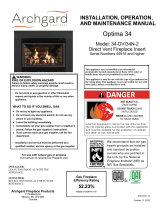
SPECIFICATIONS
FIREPLACE DIMENSIONS
DESCRIPTION Height Width Back
Width
Depth Opening
Width
Glass
Dimensions
FIREPLACE
DIMENSIONS
Inches 20” 28 1/2” 17 5/8” 17 1/4” 30 3/4” 16” x 25 1/4”
Millimeters 508mm 724mm 448mm 438mm 768mm 406mm x 641mm
CLEARANCES
Mantle 8” from top of fireplace (see chart on page #11) 35” 889mm
Sidewall (see page #11) 7” 178mm
Floor ( see page #9) 3” 76mm
Barrier Screen
Fig. 6-C
Fig. 6-D
Fig. 6-B
Fig. 6-A
LEFT
RIGHT
FRONT
LEFT RIGHT
BOTTOM
FRONT
REAR
CONTROLS FORWARD
Exhaust
Intake
25.25
29.75

7
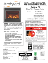
SPECIFICATIONS
As an option, the gas valve and/or control module can be moved to a “rear” position. The fireplace has optional mounting holes/
studs for the valve and module to enable their movement.
By moving the controls to the rear position, it enables you to install the unit into a smaller or irregular opening.
CONTROLS REAR
Exhaust
Intake
Valve and module shown
in “REAR” position
FRONT
Barrier Screen
RELOCATING CONTROLS
If you have a non-standard sized fireplace, the fireplace controls can be relocated to
the rear of the unit to ease installation.
Valve relocate:
1. Remove valve from fireplace. (2) screws on the top and bottom clips. Do not
discard the valve brackets.
2. Remove cable bracket and discard
3. Relocate valve to the pre-punched holes. (use the holes from the cable
bracket)
Module relocate:
1. Remove cable cover and discard. Replace screws after removing the cover.
2. Loosen off the nuts holding the module and move to the real studs.
3. Secure the module using existing nuts. Coil up the control wiring so it does
not impeded the module slide.
29.75
25.25
Remove and discard bracket
Mounting holes

8
MINIMUM OPENING DIMENSIONS
J
SIDE VIEW
TOP VIEW
L
M
K
DIMENSIONS
Controls Forward Controls Back
Inches Millimeters Inches Millimeters
J 20” 508 20” 508
K 18” 457 18” 457
L 17 3/4” 451 22 1/4” 565
M 30 3/4” 781 28 3/4” 730
Min flue size required 4” (102) x 7” (178)
ATTENTI0N
The fireplace flue damper must be fully blocked
open or removed for installation of the gas fire-
place insert.
The fireplace and fireplace chimney must be
clean and in good working order and constructed
of non-combustible materials. The chimney
cleanouts must fit properly.
LEVELING THE UF-0500/ UF-0510
This unit is equipped with front and rear leveling feet. The fireplace has the ability to independently level
left/right and front/back.
The rear leveling is done from inside the firebox. Access the leveling legs under the plugs in the upper cor-
ners of the burner. The legs can be adjusted using a slot head or nut driver. The legs will give a 1 3/4”
height adjustment.
Leveling legs for the front of the unit are included in the manual bag if required.
WARNING DO NOT remove the rear adjusters from the fireplace.
If you do not need to raise the unit. Leave them secured in place
Rear Leg adjustment
access plugs
DO NOT REMOVE

9
SIDE VIEW
WARNING Failure to position the parts in accordance with these diagrams or failure to use only parts specifically approved
with this appliance may result in property damage or personal injury or loss of life.
CAUTION This appliance is designed for use in any masonry or factory built wood-burning fireplace. It cannot be enclosed
by combustible material and used as a built-in gas fireplace.
Non–Combustible Zone
3”
16”
Fig. 9-A
WARNING
Any hearth extending out in front of the insert must not
have any portion above 3” below the bottom of the unit
made from combustible materials. This includes any
type of framing underneath a non-combustible material
such as tile, marble or stone. Any material below 3” can
be combustible.
All specified clearances must be maintained from the top
surface of carpeting, tile, etc.
Non–Combustible Zone
3”
16”
Fig 9-B
NOTE
If existing wood fireplace hearth protection is removed
it must be replaced by a non-combustible hearth protec-
tion 3” thick, extending a minimum of 16” (406 mm)
from the front of the fireplace insert or have a mini-
mum 3” (178 mm) clearance below the level of the bot-
tom of the insert.
All specified clearances must be maintained from
the top surface of carpeting, tile, etc.
SIDE VIEW
MINIMUM OPENING DIMENSIONS

10
FACTORY BUILT - (METAL) WOOD BURNING
FIREPLACE REQUIREMENTS
The metal floor of the firebox may be removed only if the following is strictly adhered to.
The metal floor (J) may be removed to allow additional room for installation of the insert. If the floor is removed the
insert must be placed directly on the metal base of the metal fireplace. Under no circumstance can it be placed
directly on a combustible material.
Any hearth extending out in front of the insert must not have any portion above 3” below the bottom of the unit
made from combustible materials. This includes any type of framing underneath a non-combustible material such as
tile, marble or stone. Any material below 3” can be combustible.
NOTE Any parts that are removed must be saved and re-installed if insert is ever removed.
ATTENTI0N
The fireplace must be permanently marked to indicate that it has been altered and is no
longer suitable for burning any fuel unless the removed parts are reinstalled. Cutting out of
any metal parts is prohibited, except the metal floor (J) as specified.
The damper (A) and grate (B) must be removed
The smoke shelf (C), internal baffles (D), screen
( E), masonry lining or refractory (G and I), and
metal or glass doors (F) may be removed.
BEDROOM INSTALLATIONS
In Canada, bedroom installations require a thermostat to be installed to control the operation of the fireplace. The remote control
supplied with the unit has the ability to manually override the thermostat which is not acceptable for Canadian installations.
The module must be put into “manual” mode (see manual operation on pg#33) to be operated only by the thermostat. In this
mode the fireplace will only operate on high fire and have no fan speed control.

11
7”
(178 mm) Clearances to Door Frame
Sidewalls or Mantle Supports
Minimum 7” (178 mm)
clearance is required from the
glass door frame to a sidewall or
mantle support.
7”
(178 mm)
Fig. 11-B
TOP VIEW
WARNING Failure to position the parts in accordance with these diagrams or failure to use only parts specifically approved
with this appliance may result in property damage or personal injury.
CAUTION Mantle depth maybe increased/decreased 1” (25.4 mm) for each 1” (25.4 mm) change in corresponding
clearance height. Mantle depth of less than 1” is not considered a mantle
MANTLE CLEARANCES
12”
9”
6”
3”
1”
33”
28”
30”
36”
39”
Based on
SMALL SURROUND 27” H
Fig. 11-A

12
This fireplace is manufactured for use with Natural Gas. Follow the instructions included with the conversion kit
if converting to LP gas, (Sold separately).
Adequate clearance for proper installation and checking of the gas connections must be provided. All gas
connections must be checked for gas leaks.
GAS LINE CONNECTIONS
GAS CONVERSION
This fireplace is equipped with a 3/8” (10mm) x 8” (203mm) long flexible gas connector and manual shut-off valve. The gas
line should be run to the point of connection where the shut-off valve and flexible gas line will connect
NOTE
The appliance and its individual shut-off valve must be disconnected from the gas supply piping system during
any pressure testing of that system at pressures in excess of 1/2 psi (3.5 kPa)
The appliance must be isolated from the gas supply piping system by closing its individual manual shut-off valve
during any pressure testing of the gas line at test pressures equal to or less than 1/2 psi (3.5 kPa)
For high altitude installations, consult the local gas distributor or the authority having jurisdiction for proper rat-
ing methods.
IMPORTANT The efficiency rating of this appliance is a product of the thermal efficiency rating determined under
continuous operating conditions and was determined independently of any installed system
CAUTION Installation of the gas line must only be done by a qualified person in accordance with local building
codes, if any. If not, follow ANSI 223.1.
Natural Gas (NG) Propane (LP)
Manifold Pressure 3.8 in. W.C. (0.95 kPa) 11.0 in. W.C. (2.5 kPa)
Min. Supply Pressure 5 in. W.C. (1.25 kPa) 11.0 in. W.C. (2.8 kPa)
Max Supply Pressure 10.5 in. W.C. (3.5 kPa) 13.0 in. W.C. (3.5 kPa)
Orifice Size #33 DMS (2.86 mm dia) #51 DMS (1.73 mm dia)
Nominal Input Rating 17,500 - 31,500 BTU/hr (5.1- 9.2kW) 15,000 - 29,500 BTU/hr (4.4 -8.65kW)
Electrical Rating 120 VAC, 60Hz less than 2 A. / 120 VAC, 60Hz less than 2 A. /
Gas Control SIT 885 Proflame II SIT 885 Proflame II
Altitude 0 - 4,500 ft. (0 - 1372 M) 0 - 4,500 ft. (0 - 1372 M)
Primary Air Opening 1/4” (6 mm) OPEN FULLY OPEN
When installing this appliance beyond 4500 ft. (1372 M) above sea level, the appliance must be properly de-rated
and installed according to local codes, in the absence of local codes, with the current National Fuel Gas Code, ANSI
Z223.1/ NFPA 54, in the US or Installation Code, CAN/CGA-B149, in Canada.
HIGH ALTITUDE INSTALLATION

13
1. Remove the surround.
2. The pressure taps are located on the gas valve front face. The inlet is marked ‘IN’.
3. Loosen the set screw inside the tap and attach a manometer using 1/4” (6 mm) rubber tube to the tap post
4. Light pilot and burner. Check pressure to ensure it is between recommended min-max pressure settings.
5. Turn off burner and pilot
6. Remove manometer and hose. Tighten the set screw inside the tap after you finish taking pressure readings.
7. Check for leaks.
CHECKING INLET PRESSURE
PRESSURE TESTING
GAS VALVE
Outlet pressure tap
Inlet pressure tap
CHECKING OUTLET PRESSURE
1. Light Pilot
2. The pressure test taps are located on the valve. The taps are located in the gas valve front face. The inlet is
marked ‘OUT’.
3. Loosen the set screw inside the tap and connect a 1/4” (6 mm) rubber tube to the tap post and a manometer.
4. Verify that the readings obtained are within specs (as shown on the appliance rating plate)
5. Be sure to tighten the set screw inside the tap after you finish taking pressure readings.
6. Check for leaks.
Pilot adjust screw
0.885.009

14
ELECTRICAL CONNECTIONS
.Do not cut or remove the grounding prong from this plug.
NOTE: This appliance, when installed, must be electrically grounded in accordance with local codes or, in
the absence of local codes, with the National Electrical Code, ANSI / NFPA 70, or the Canadian
Electrical code, CSA C22.1.
LIGHT KIT
CAUTION Disconnect all electrical power from the fireplace before performing this task
NOTE To avoid damage and prolong the life of the halogen bulbs, never touch with bare hands. Always use
a soft cloth when handling.
The UF-0500/0510 comes complete with a variable speed fan wired directly to the main control module
for your protection against shock hazard
This fireplace is equipped with an adjustable accent light feature. For those times when you want to enjoy the ambiance of a soft
glow without having the efficient heat output. The handheld remote gives you the ability to adjust the light in the fireplace to 6
different levels.
Module
Light Light
B
W
The lights are installed below the burner. To replace the bulbs when they
burn out, burner removal is required. Bulbs are a mini candelabra type
and screw out.
Replacement bulbs can be purchased from your installer or from most
lighting supply stores.

15
WIRING SCHEMATICS

16
VENTING
WARNING: Operation of this heater when not connected to a properly installed and maintained venting sys-
tem can result in carbon monoxide (CO) poisoning and possible death. The appliance must not be connected
to a chimney flue serving a separate solid fuel burning appliance.
The flue length must be a minimum of 10’ (3.05 M) and a maximum of 40’ (12.2 M). Refer to the following page for details.
The minimum (chimney) flue size is 4” x 7” (102 mm X 178 mm).
Masonry chimneys may take various contours which the flexible liner will accommodate, however, keep the flexible liner as
straight as possible, avoiding unnecessary bending but at all times keep a minimum of 3” (76 mm) inside bend radius.
The Air Intake Flex Liner must be connected to the inlet air collars of the termination cap and the appliance. The Exhaust Flex
Liner must be connected to the exhaust collars of the termination cap and the appliance.
(DO NOT REVERSE THESE CONNECTIONS).
APPROVED VENT TERMINATIONS / KITS
CAUTION
To ensure that the venting is not accidentally obstructed or punctured, the damper of the host fire-
place must be permanently disabled by either complete removal of the damper, or welding it in its
“open” position. Temporarily disabling the damper with braces, wedges, brackets, etc., is not allowed
NOTE This appliance is designed for both 3” (76 mm) double wall aluminum flex gas liners to run the full
length of the chimney (see page 16) and connect to an approved termination
ATTENTION .NO OTHER VENTING SYSTEM OR COMPONENTS MAY BE USED. Follow manufacturer
instructions for installation of termination.
CAUTION Only 3” (76 mm) UL Listed double wall aluminum flex vent liners (or approved equivalent) and one
of the above vent terminals are approved for use with this appliance.
Manufacturer Vertical Termination Termination Kit
Archgard 999-INS-TK N/A
Dura Vent 46DVA 46DVA-CL33
BDM High wind w/ square base
Rectangle VCL
Round VCL
940033ECHWS
940033EC26SS
9400342RDSS
Ameri-vent 4DCA 4DCAT33
Selkirk 4DT-VT 4DT-CTB

17
VENTING INSTRUCTIONS 999-INS-TK
Instructions for use with Archgard vertical termination cap. Part # 999-INS-TK
Install the termination cap being sure to provide sufficient space (around and on top) so as not to impede the
flow of air, both into and out of the cap. This cap is only to be used for non combustible installations. Do not
recess into the top of the chimney.
1. Mark each end of one liner with “Air Intake”.
2. Mark each end of the second liner with “Exhaust”.
3. Pull the liner through the chimney.
4. Install the flashing.
5. Seal and attach the liner marked “Air Intake” to the vent terminal pipe marked “Air Intake” with the collar
clamp provided.
6. Seal and attach the liner marked “Exhaust” to the vent terminal pipe marked “Exhaust” with the collar clamp
provided.
7. Seal and attach the end of the flex marked “Air Intake” to the collar marked “Air Intake” on the appliance
with the collar clamp provided with the unit.
8. Install exhaust vent restrictors provided with the unit if required. Seal and attach the end of the flex
marked “Exhaust” to the collar marked “Exhaust” on the appliance.
9. Caulk all joints using a high temperature sealant such as milpac. DO NOT USE SILICONE SEALANTS.
Use of silicon sealants voids the warranty of the pilot assembly.
NOTE: The vertical termination cap must be sealed to the liner with suitable high temperature sealant, such as mil-
pac and with the hose clamps fasteners provided. DO NOT USE SILICONE SEALANTS (Use of silicon sealants
voids the warranty of the pilot assembly) The liners must form a complete connection from the appliance flue
collars to the vertical termination cap.
The minimum flue (chimney)
size required to run the two
3” (76 mm) is 4” x7” (100
mm X 178 mm)
Front view of
DV Insert
Exhaust
Collar
Air Intake
Collar
3” (76 mm) Flex Liner
Fresh Air Intake
Min. vent height 10’(2.54 M)
Max. vent height 40’ (12.2 M)
Vertical Termination cap
Fig. 17-A
N O T E
Seal and secure liners on unit and
at roof termination

18
VENTING
VENT RESTRICTOR INSTALLATION
Archgard Termination:
999-INS-TK
3” 3”
Secure the flexible liner at the top of the fireplace and at the termination. DO NOT use
silicone as this will void the flame sensor warranty. Use mil-pac or other non silicone seal-
ant and three (3) screws or gear clamps to seal the liner at each end.
Mil-pac
Roof Termination
Fig. 18-D
Fig. 18-E
Screws or
gear clamp
Mil-pac
Screws or
gear clamp
DO NOT USE SILICONE TO SEAL VENT
SEALING THE VENT
Restrictor installed
in upper baffle.
Center air channel
is closed off with
restrictor
Firebox baffle w/out
restrictor.
All three air channels
in the baffle are open
When the vent is over 18’(5.5m) a vent restrictor may be required. The installation of the restrictor will equalize the vent
stack action that can cause problems with a proper fire set-up.
The vent restrictor is supplied loose in the manual bag. When required, it installs onto the upper baffle in the center portion.
The baffle air openings are located in the top of the firebox just inside the front frame of the fireplace. There are holes al-
ready in the standoffs that will line up with the holes in the restrictor.
Upper Baffle
air channels Upper Baffle
Restrictor

19
UF0500 LOG PLACEMENT
Log# 2
Place log #2 on the lower left front of the burner. Align the hole in
the bottom of the log and set the log into place
Log# 1
Align the holes of log# 1 with the two locater pins at the back of the
burner. Set the log onto the pins with gentle force.
NOTE Installing the fiber logs in any other position other than shown will result in flame
impingement causing sooting of the logs, brick liner and ceramic glass viewing area.
LOCATOR PINS
Pilot Cover
Log# 3
Log #3 locates on the front right side of the burner. Secure log to the
two locator pins.
LOG 2
LOG 1
LOG 3
CAUTION DO NOT block pilot opening with embers or glass media material

20
UF0500 LOG PLACEMENT…. Con’t
Log# 4
Rest the back of Log #4 on the locator pin on the back edge of
Log #3. Place the front of Log #4 onto the burner locator pin.
LOG 4
Log# 5
Rest Log #5 on top of Log #1 along the rear right hand side. The
right side of Log #5 rests in the notch in Log #4
LOG 5
Log# 6
Rest Log #6 on top of Log #1 along the rear left hand side. The left
side of Log #6 rests on the left side of Log #2.
LOG 6
Log# 7
Rest the sculpted hollow end of Log #7 on top of Log #4 and angle
the log back and to the left as shown in the picture.
LOG 7
WARNING Failure to position the logs in accordance with the preceding diagrams or failure to use only parts
specifically approved with this appliance may result in property damage or personal injury.
/