Page is loading ...

Instruction D11000
November 2016
2-36” (50mm—900mm)
KGN-MSU
UNIDIRECTIONAL CAST
STAINLESS STEEL
KNIFE GATE VALVES

DeZURIK
Instruction and Operating Manual Page 2 © 2022 DeZURIK, Inc.
Instructions
These instructions are for use by personnel who are responsible for the installation, operation and
maintenance of DeZURIK valves, actuators or accessories.
Safety Messages
All safety messages in the instructions are identified by a general warning sign and the signal word CAUTION,
WARNING or DANGER. These messages indicate procedures to avoid injury or death.
Safety label(s) on the product indicate hazards that can cause injury or death. If a safety label becomes difficult
to see or read, or if a label has been removed, please contact DeZURIK for replacement label(s).
Personnel involved in the installation or maintenance of valves should be constantly alert to potential
emission of pipeline material and take appropriate safety precautions. Always wear suitable protection
when dealing with hazardous pipeline materials. Handle valves which have been removed from service
with suitable protection for any potential pipeline material in the valve.
Inspection
Your DeZURIK product has been packaged to provide protection during shipment; however, items can be
damaged in transport. Carefully inspect the unit for damage upon arrival and file a claim with the carrier if
damage is apparent.
Parts
Replaceable wear parts are listed on the assembly drawing. These parts can be stocked to minimize
downtime. Order parts from your local DeZURIK sales representative or directly from DeZURIK. When ordering
parts please provide the following information:
If the valve has a data plate: please include the 7-digit part number with either 4-digit revision number
(example: 9999999R000) or 8-digit serial number (example: S1900001) whichever is applicable. The
data plate will be attached to the valve assembly. Also, include the part name, the assembly drawing
number, the balloon number and the quantity stated on the assembly drawing.
If there isn't any data plate visible on the valve: please include valve model number, part name, and
item number from the assembly drawing. You may contact your local DeZURIK Representative to help
you identify your valve.
DeZURIK Service
DeZURIK service personnel are available to maintain and repair all DeZURIK products. DeZURIK also offers
customized training programs and consultation services. For more information, contact your local DeZURIK
sales representative or visit our website at DeZURIK.com.

November 2016 D11000
Description 3
Installation 3
Operation 3
Lubrication 3
Packing 3
Drawings 4
Packing Replacement 5
Removing the Old Packing 5
Installing the New Packing 5
Reassembling the Valve 6
Gate Replacement 6
Troubleshooting 7
Adjustment 3
Table of Contents
DeZURIK
2-36” (50—900mm) KGN-MSU METAL SEATED KNIFE GATE VALVES

Description
The DeZURIK KGN-MSU knife gate valves are bonnetless valves with a stainless steel body and
gate, and an all-metal seat. A choice of several actuators and accessories are available.
Installation
Install the valve between ASME Class 125 or Class 150 pipeline
flanges. Flange gaskets are required. Before installation, remove
foreign material such as weld spatter, oil, grease, and dirt from the
valve and pipeline.
Install the valve so that the side marked "SEAT" is on the lower
pressure side of the valve when the valve is closed; the pipeline
pressure will then help seal the valve in the closed position.
Observe the following points to prevent distortion of the valve body
and gate when the flange bolts are tightened:
Align the mating pipeline flanges.
Select the length of the flange bolts so that the bolts used in
the blind holes do not bottom out when tightened.
Tighten the flange bolts evenly, in a crisscross pattern. Re-
fer to Table A for recommended flange bolt-stud torques.
Operation
The gate in the valve is positioned by the valve actuator. The actua-
tor moves the gate over the valve seat in the closed position, and
withdraws the gate from the seat in the open positions. Refer to the
Actuator Instructions for adjustment and maintenance requirements
for the actuator.
Lubrication
The valve does not require lubrication. If applicable, ensure that
valve threaded stems are maintained with proper lubrication. Refer
to the Actuator Instructions for lubrication requirements for the ac-
tuator.
Packing
The gate packing is contained and compressed by the packing
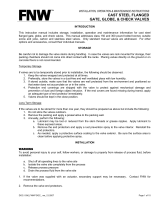
gland. See Figure 1 for component identification.
Adjustment
If packing leaks, tighten the adjustment nuts on top of the packing
gland. Tighten the nuts evenly and gently — just enough to stop the
leak. Over tightening will cause excessive operating forces, and will decrease the life of the packing.
Note: Torque ranges are based on ASME Pressure Vessel Code Calculations and lab test data.
These torques are only for the listed gasket types. For other gasket types listed in ASME, consult
DeZURIK.
D11000 Page 3 November 2016
Valve
Size
ASME Gasket Types;
Rubber, Soft Fabric
Filler, or 1/8” Thick
Hard
2”
50mm 26 - 29
3”
80mm 37 - 41
4”
100mm 26 - 29
6”
150mm 41 - 45
8”
200mm 55 - 61
10”
250mm 56 - 62
12”
300mm 80 - 88
14”
350mm 107 - 118
16”
400mm 103 - 114
18”
450mm 128 - 141
20”
500mm 123 - 136
24”
600mm 188 - 207
Table A: Recommended
Flange Bolt/Stud Torque
Range in ft-lbs (non-
lubricated)
30”
750mm 198 - 218
36”
900mm 289 - 318
DeZURIK
2-36” (50—900mm) KGN-MSU METAL SEATED KNIFE GATE VALVES

Figure 1—Component Identification
Drawings
November 2016 Page 4 D11000
Gate
Nut
Washer
Gland
Bolt
Packing
Body
DeZURIK
2-36” (50—900mm) KGN-MSU METAL SEATED KNIFE GATE VALVES

Packing Replacement
Removing the Old Packing
1. Relieve the pressure in the pipeline and close the valve.
2. If the actuator is powered, disconnect and
lock out power to prevent accidental opera-
tion of the actuator.
3. Remove the two screws and nuts near the top
of the gate and disengage the stem from the
gate by stroking the actuator (not the valve) to
the open position.
5. Remove the gland nuts, washers and the
packing gland.
6. Remove the used packing from the packing
chamber.
Installing the New Packing
It is recommended to use a square-ended wood or
plastic tool, driven by a hammer or mallet for packing
rings.
Note: DO NOT USE ANY SHARP TOOLS TO
PACK THE RINGS.
1. With the gate closed, center the gate in the body below the packing chamber.
2. Cut new packing rings to the length and quantity shown in Table B.
3. Install and pack the rings one at a time in the sequence shown in Figure 2.
Note: Make sure the inside and outside edges of each ring are tightly packed against the gate and
packing chamber, especially in the corner areas. Pack each ring until it is flat and even.
D11000 Page 5 November 2016
WARNING!
Pipeline pressure can cause personal injury or equipment damage. Re-
lieve pipeline pressure before removing gate stem and packing gland
nuts.
WARNING!
Accidental operation of power actuator can cause personal injury or
equipment damage. Disconnect and lock out power to actuator before
servicing.
DeZURIK
2-36” (50—900mm) KGN-MSU METAL SEATED KNIFE GATE VALVES
VALVESIZE#LAY‐
ERSOF
PACKING
PACKING
SIZE[in]
LENGTHOF
PACKINGIN
EACHLAYER[in]
inmm
25033/87.3
38033/88.9
410033/810.6
615033/814.8
820033/818.7
1025033/822.6
1230037/1626.6
1435031/229.9
1640031/234.1
1845031/238.0
2050035/842.9
2460035/850.8
3075041/266.1
3690035/879.9
TABLE B: Packing Ring Lengths

Packing Replacement continued
With standard packing all the rings are the same material. With packing cord the packing cord ring is
the second ring from the bottom. With the scraper ring option the scraper ring is the bottom ring.
Reassembling Valve
1. Replace the packing gland, washers, and nuts. Tighten the nuts evenly and finger tight, plus 1/2
turn.
2. Reconnect the stem to the gate with the two screws and nuts.
3. If the actuator is a powered actuator, reconnect power to the actuator.
4. Pressurize the pipeline and inspect packing for leakage.
5. If packing leaks, tighten the adjustment nuts on top of the packing gland. Tighten the nuts evenly
and slowly, just enough to stop the leak. Over tightening will cause excessive operating forces,
and will decrease the life of the packing.
Gate Replacement
See Figure 1 for component identification
1. Relieve the pressure in the pipeline and close the valve.
November 2016 Page 6 D11000
WARNING!
Pipeline pressure can cause personal injury or equipment damage. Re-
lieve pipeline pressure before removing gate stem and packing gland
nuts.
WARNING!
Accidental operation of power actuator can cause personal injury or
equipment damage. Disconnect and lock out power to actuator before ser-
vicing.
DeZURIK
2-36” (50—900mm) KGN-MSU METAL SEATED KNIFE GATE VALVES
Packing Cord
Figure 2—Packing Ring Sequence
Standard Scraper Ring
PACKING
BODY
GATE
PACKING
BODY
GATE
PACKING
BODY
GATE
CORD
SCRAPER
PACKING
PACKING PACKING
PACKING
GLAND
GLAND
GLAND

Gate Replacement continued
2. If the actuator is powered, disconnect and lock out power to prevent accidental operation of the
actuator.
3. Remove the pipeline flange bolts, and remove the valve from the pipeline.
4. Remove the actuator, actuator yoke, packing gland, and packing from the valve.
5. Remove and inspect the gate. If the gate appears to be scratched or galled due to too-long
flange bolts in the chest area of the body, check for body damage in the tapped flange holes and
within the chest cavity. Repair or replace the body, as appropriate.
6. Inspect the seat components.
7. Replace the body if the seat is worn or damaged.
8. Place the new gate in the body, in the fully closed position.
9. Replace the packing as described in “Packing Replacement”.
10. Replace the yoke and actuator on the valve.
11. Adjust the actuator, yoke, and packing gland so that the valve actuates smoothly full stroke in
both directions, and so that there is no evidence of binding or scratching on the gate when the
gate is visible in the fully open position.
12. Replace the valve in the pipeline as described in the “Installation” section.
13. If the actuator is a powered actuator, reconnect power to the actuator.
14. Pressurize the pipeline and inspect the valve for leaks.
15. If the packing leaks, tighten the adjustment nuts on top of the packing gland. Tighten the nuts
evenly and slowly, just enough to stop the leakage. Over tightening will cause excessive operat-
ing forces, and will decrease the life of the packing.
Troubleshooting
D11000 Page 7 November 2016
Condition Possible Causes
Corrective
Action
Packing is loose Adjust packing gland
Packing is worn or torn Replace packing
Packing leaks and gate is
galled Packing is worn or torn Replace packing and
gate
Valve leaks when fully
closed, with no evidence of
galling on gate
Metal seat is worn Replace valve
Valve leaks when fully closed
and gate is galled Metal seat is worn Replace valve
Packing leaks, with no evi-
dence of galling on gate
DeZURIK
2-36” (50—900mm) KGN-MSU METAL SEATED KNIFE GATE VALVES

Limited Warranty
DeZURIK, Inc. (“Seller”) manufactured products, auxiliaries and parts thereof that we manufacture for a period of twenty-four (24) months from date
of shipment from Seller’s factory, are warranted to the original purchaser only against defective workmanship and material, but only if properly stored,
installed, operated, and serviced in accordance with Seller’s recommendations and instructions.
For items proven to be defective within the warranty period, your exclusive remedy under this limited warranty is repair or replacement of the defective
item, at Seller’s option, FCA Incoterms 2020 Seller’s facility with removal, transportation, and installation at your cost.
Products or parts manufactured by others but furnished by Seller are not covered by this limited warranty. Seller may provide repair or replacement
for other’s products or parts only to the extent provided in and honored by the original manufacturer’s warranty to Seller, in each case subject to the
limitations contained in the original manufacturer’s warranty.
No claim for transportation, labor, or special or consequential damages or any other loss, cost or damage is being provided in this limited warranty.
You shall be solely responsible for determining suitability for use and in no event shall Seller be liable in this respect.
This limited warranty does not warrant that any Seller product or part is resistant to corrosion, erosion, abrasion or other sources of failure, nor does
Seller warrant a minimum length of service.
Your failure to give written notice to us of any alleged defect under this warranty within twenty (20) days of its discovery, or attempts by someone other
than Seller or its authorized representatives to remedy the alleged defects therein, or failure to return product or parts for repair or replacement as
herein provided, or failure to store, install, or operate said products and parts according to the recommendations and instructions furnished by Seller
shall be a waiver by you of all rights under this limited warranty.
This limited warranty is voided by any misuse, modification, abuse or alteration of Seller’s product or part, accident, fire, flood or other Act of God, or
your failure to pay entire contract price when due.
The foregoing limited warranty shall be null and void if, after shipment from our factory, the item is modified in any way or a component of another
manufacturer, such as but not limited to; an actuator is attached to the item by anyone other than a Seller factory authorized service personnel.
All orders accepted shall be deemed accepted subject to this limited warranty, which shall be exclusive of any other or previous warranty, and this
shall be the only effective guarantee or warranty binding on Seller, despite anything to the contrary contained in the purchase order or represented by
any agent or employee of Seller in writing or otherwise, notwithstanding, including but not limited to implied warranties.
THE FOREGOING REPAIR AND REPLACEMENT LIMITED WARRANTY IS IN LIEU OF ALL OTHER WARRANTIES, OBLIGATIONS AND
LIABILITIES, INCLUDING, BUT NOT LIMITED TO, ALL WARRANTIES OF FITNESS FOR A PARTICULAR PURPOSE OR OF MERCHANTABILITY
OR OTHERWISE, EXPRESSED OR IMPLIED IN FACT OR BY LAW, AND STATE SELLER’S ENTIRE AND EXCLUSIVE LIABILITY AND YOUR
EXCLUSIVE REMEDY FOR ANY CLAIM IN CONNECTION WITH THE SALE AND FURNISHING OF SERVICES, GOODS OR PARTS, THEIR
DESIGN, SUITABILITY FOR USE, INSTALLATION OR OPERATIONS. NEITHER ANY PERFORMANCE OR OTHER CONDUCT, NOR ANY ORAL
OR WRITTEN INFORMATION, STATEMENT, OR ADVICE PREPARED BY SELLER OR ANY OF OUR EMPLOYEES OR AGENTS WILL CREATE A
WARRANTY, OR IN ANY WAY INCREASE THE SCOPE OR DURATION OF THE LIMITED WARRANTY.
Disclaimer
Metric fasteners should not be used with ASME Class 150/300 bolt holes and flange bolt patterns. If you use metric fasteners with ASME Class 150/300
bolt holes and flange bolt patterns, it may lead to product failure, injury, and loss of life. DeZURIK Inc. disclaims all liability associated with the use of
metric fasteners with ASME Class 150/300 bolt holes and flange patterns, including but not limited to personal injury, loss of life, loss of product,
production time, equipment, property damage, lost profits, consequential damages of any kind and environment damage and/or cleanup. Use of metric
fasteners with ASME Class 150/300 bolt holes and flange bolt patterns is a misuse that voids all warranties and contractual assurances. If you use
metric fasteners with ASME Class 150/300 bolt holes and flange bolt patterns, you do so at your sole risk and any liability associated with such use shall
not be the responsibility of DeZURIK, Inc. In addition to the foregoing, DeZURIK’s Manufacturer’s Conditions apply.
Limitation of Liability
IN NO EVENT SHALL SELLER BE LIABLE FOR ANY DIRECT, INDIRECT, SPECIAL, PUNITIVE, EXEMPLARY, OR CONSEQUENTIAL DAMAGES
(INCLUDING, BUT NOT LIMITED TO; DAMAGE TO OR LOSS OF OTHER PROPERTY OR EQUIPMENT, BUSINESS INTERUPTION, COST OF
SUBSTITUTE PRODUCTS, LOSS OF TIME, LOSS OF PROFITS OR REVENUE, COST OF CAPTIAL, LOSS OF USE, OR DIMINUTION IN VALUE)
WHATSOEVER, AND SELLER’S LIABILITY, UNDER NO CIRCUMSTANCES, WILL EXCEED THE CONTRACT PRICE FOR THE GOODS AND/OR
SERVICES FOR WHICH LIABILITY IS CLAIMED. ANY ACTION FOR BREACH OF CONTRACT BY YOU, OTHER THAN RIGHTS RESPECTING OUR
LIMITED WARRANTY DESCRIBED ABOVE, MUST BE COMMENCED WITHIN 12 MONTHS AFTER THE DATE OF SALE.
Sales and Service
For information about our worldwide locations, approvals, certifications and local representative:
Web site: www.dezurik.com E-Mail: info@dezurik.com
250 Riverside Ave. N., Sartell, MN 56377 ● Phone: 320-259-2000 ● Fax: 320-259-2227
DeZURIK, Inc. reserves the right to incorporate our latest design and material changes without notice or obligation.
Design features, materials of construction and dimensional data, as described in this manual, are provided for your information only
and should not be relied upon unless confirmed in writing by DeZURIK, Inc. Certified drawings are available upon request.
December 2022
/