13
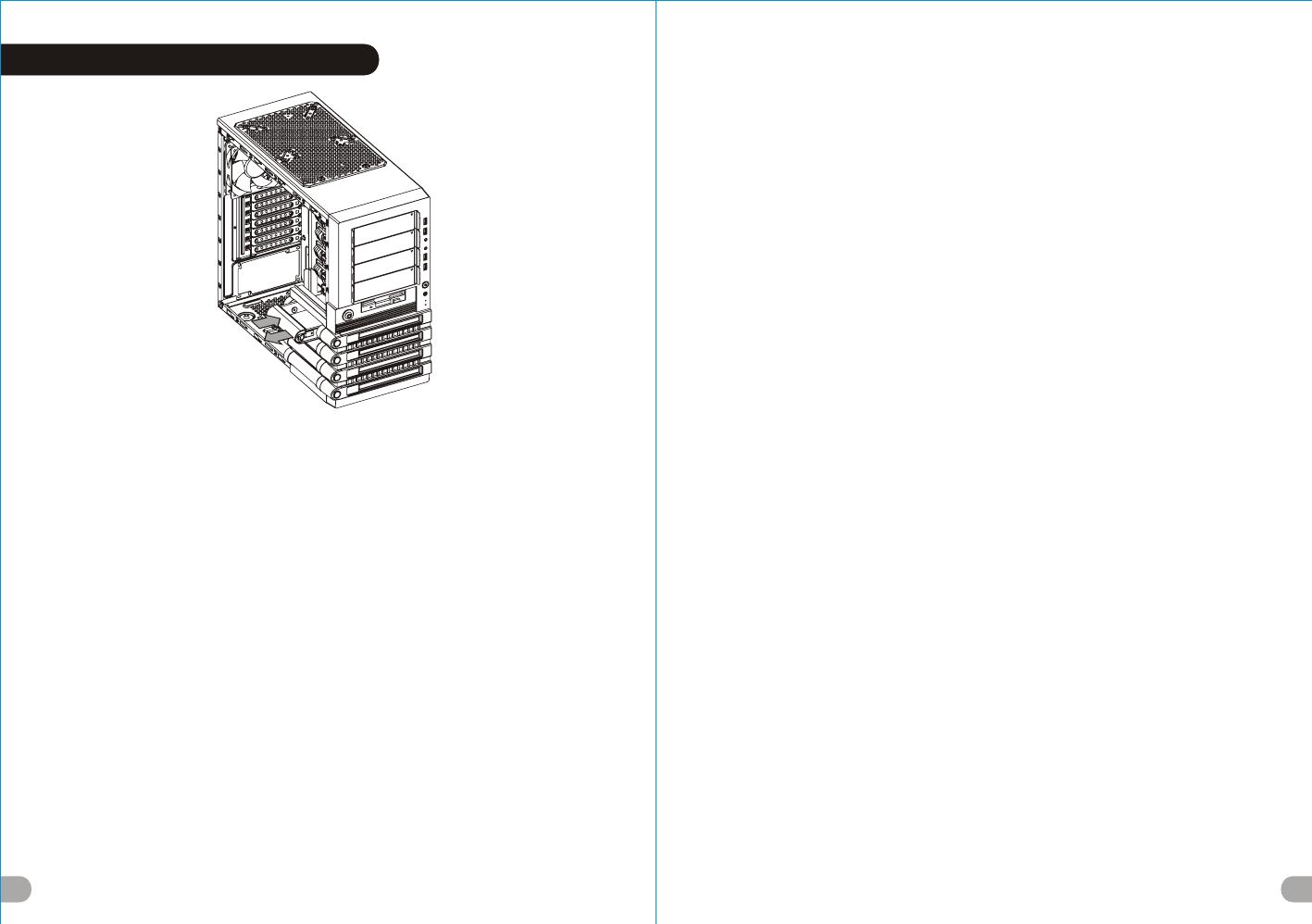
EasySwap HDD Installation
14
English /
The Easy Swap slot is embedded to enable ultra fast
transfer (up to 3.0Gbps) of large data to a SATA hard disk
without having to use an external storage enclosure. To
ensure proper operation, please make sure the following
settings are correct:
1. Ensure all required drivers are installed for your
motherboard or SATA controller card.
2. Squeeze to pull the HDD tray out.
3. Mount the 3.5” HDD into the tray with screws provided.
4. Slide the HDD tray back to the HDD cage.
5. Connect the SATA cable to an available SATA
connector on the motherboard or SATA controller card.
6. Connect the power cable to power supply.
7. Ensure AHCI (Advanced Host Controller Interface) is
enabled on your motherboard or SATA controller card. The
AHCI enables for “hotswap” capability of the SATA hard
drives without having to turn off the computer prior to
connecting or disconnecting of the hard drive. Please
follow instruction provided by your motherboard or SATA
controller card to enable the AHCI function.
If you are using a brand new hard drive, the hard drive will
need to be initialized (formatted) before it is accessible.
For more information on how to initialize (format) a new
hard drive, please refer to the hard drive user manual or
visit
System running on Windows 7:
http://www.thermaltakeusa.com/Faq.aspx?ID=1143
System running on Windows Vista:
http://www.thermaltakeusa.com/Faq.aspx?ID=1079
System running on Windows XP:
http://www.thermaltakeusa.com/Faq.aspx?ID=1073
Deutsch /
Der Easy Swap-Einführungsschlitz st eingelassen, um einen
ultraschnellen Transfer (bis zu 3,0 GB/s) von umfangreichen
Daten zur SATA-Festplatte zu ermöglichen, ohne dafür ein
externes Gehäuse verwenden zu müssen. Um einen
ordnungsgemäßen Betrieb zu gewährleisten, stellen Sie bitte
sicher, dass die folgenden Einstellungen richtig sind:
1. Stellen Sie sicher, dass alle erforderlichen Treiber für Ihr
Mainboard oder SATA Controller-Karte installiert sind.
2. Drücken, um das HDD-Fach herauszuziehen.
3. Montieren Sie die 3,5" HDD mit den mitgelieferten
Schrauben in das Fach.
4. Schieben Sie den HDD-Schacht zurück in den HDD-Käfig.
5. Verbinden Sie das SATA-Kabel mit einen freien SATA-
Anschluss auf dem Mainboard oder der SATA Controller-
Karte.
6. Verbinden Sie das Stromkabel mit dem Netzteil.
7. Stellen Sie sicher, dass AHCI (Advanced Host Controller
Interface) auf dem Motherboard oder der SATA-Controller-
Karte aktiviert ist. AHCI ermöglicht die "HotSwap"-Funktion
der SATA-Festplatten, ohne dass Sie den Computer
ausschalten müssen, bevor Sie die Festplatte anschließen
oder entfernen. Bitte folgen Sie den Anweisungen Ihres
Motherboards oder der SATA-Controller-Karte, um die AHCI-
Funktion zu aktivieren.
Wenn Sie eine neue Festplatte benutzen, muss die Festplatte
initialisiert werden (formatiert), bevor sie nutzbar ist. Weitere
Informationen darüber, wie man eine neue Festplatte
formatiert, entnehmen Sie bitte dem Benutzerhandbuch zur
Festplatte oder besuchen Sie
System läuft unter Windows 7:
http://www.thermaltakeusa.com/Faq.aspx?ID=1143
System läuft unter Windows
Vista:http://www.thermaltakeusa.com/Faq.aspx?ID=1079
System läuft unter Windows XP:
http://www.thermaltakeusa.com/Faq.aspx?ID=1073
Français /
La baie EasySwap est intégrée pour permettre le transfert ultra
rapide (jusqu'à 3,0 Gbits/s) de données volumineuses vers un
disque dur SATA sans devoir utiliser un boîtier de stockage
externe. Pour assurer un bon fonctionnement, veuillez vérifier la
justesse des paramètres suivants :
1.Vérifiez que tous les pilotes requis soient installés pour votre
carte mère ou votre carte contrôleur SATA.
2. Pressez pour enlever le boîtier du disque dur.
3. Fixez le disque dur de 3,5" dans le boîtier avec les vis
fournies.
4. Refaites glisser le boîtier du disque dur dans la cage de
disques durs.
5. Connectez le câble SATA à un connecteur SATA disponible
sur la carte mère ou la carte contrôleur SATA.
6. Connectez le cordon d’alimentation à l’alimentation.
7. Vérifiez que le mode AHCI (Advanced Host Controller
Interface) soit activé sur votre carte mère ou votre carte
contrôleur SATA. Le mode AHCI permet « l’échange à chaud »
des disques durs SATA sans devoir éteindre l'ordinateur avant
de connecter ou de débrancher le disque dur. Veuillez suivre les
directives de votre carte mère ou de votre carte contrôleur SATA
pour activer la fonction AHCI.
Si vous utilisez un disque dur neuf, il devra être initialisé
(formaté) avant de devenir accessible. Pour plus d'informations
sur comment initialiser (formater) un nouveau disque dur,
veuillez vous reporter au manuel de l'utilisateur du disque dur ou
visitez
Pour un système qui exécute Windows 7 :
http://www.thermaltakeusa.com/Faq.aspx?ID=1143
Pour un système qui exécute Windows Vista :
http://www.thermaltakeusa.com/Faq.aspx?ID=1079
Pour un système qui exécute Windows XP :
http://www.thermaltakeusa.com/Faq.aspx?ID=1073
Español /
La ranura de intercambio sencillo se aloja para facilitar la
transferencia ultra rápida (hasta 3,0 Gbps) de muchos datos a
un disco duro SATA sin tener que utilizar una cubierta de
almacenamiento externa. Para garantizar un funcionamiento
adecuado, asegúrese de que los siguientes ajustes son
correctos:
1. Asegúrese de que están instalados todos los controladores
necesarios para la placa base o la tarjeta controladora SATA.
2. Presione para extraer la bandeja del disco duro.
3. Monte el disco duro de 3,5” en la bandeja con los tornillos
proporcionados.
4. Vuelva a meter la bandeja del disco duro en su hueco.
5. Conecte el cable SATA a un conector SATA disponible de la
placa base o la tarjeta controladora SATA.
6. Conecte el cable de alimentación a la fuente de energía.
7. Asegúrese de que AHCI (Interfaz de controlador host
avanzada) está activada en la placa base o la tarjeta
controladora SATA. La AHCI activa la función "intercambio en
caliente” de los discos duros SATA sin tener que apagar el
equipo antes de conectar o desconectar el disco duro. Siga las
instrucciones proporcionadas por la placa base o la tarjeta
controladora SATA para activar la función AHCI.
Si utiliza un disco duro nuevo, éste necesitará inicializarse
(formatearse) antes de acceder a él. Para obtener más
información sobre cómo inicializar (formatear) un disco duro
nuevo, consulte el manual del usuario del disco duro o visite
Sistema ejecutado en Windows 7:
http://www.thermaltakeusa.com/Faq.aspx?ID=1143
Sistema ejecutado en WindowsVista:
http://www.thermaltakeusa.com/Faq.aspx?ID=1079
Sistema ejecutado en Windows XP:
http://www.thermaltakeusa.com/Faq.aspx?ID=1143
Italiano /
Lo slot con swap facile è integrato e consente un
trasferimento ultraveloce (fino a 3,0 Gbps) di grandi quantità
di dati in un disco rigido SATA senza dover usare alcun
dispositivo di archiviazione interno. Per garantire il corretto
funzionamento, verificare che le seguenti impostazioni siano
corrette:
1. Verificare che siano installati tutti i driver richiesti per la
scheda madre o la scheda del controller SATA.
2. Stringere per estrarre il vano HDD.
3. Montare l’HDD da 3,5” nel vano con le viti in dotazione.
4. Fare scorrere l’HDD indietro verso la struttura a gabbia
dell’HDD.
5. Collegare il cavo SATA ad un connettore SATA disponibile
nella scheda madre o nella scheda del controller SATA.
6. Collegare il cavo di alimentazione all’alimentatore.
7. Verificare che l’interfaccia AHCI (Advanced Host Controller
Interface) sia abilitata sulla scheda madre o sulla scheda del
controller SATA. L’interfaccia AHCI consente la funzionalità
“hotswap” delle unità rigide SATA senza dovere spegnere il
computer prima di collegare o scollegare il disco rigido.
Seguire le istruzioni fornite per la scheda madre o la scheda
del controller SATA per abilitare la funzione AHCI.
Se si utilizza il disco rigido di una nuova marca, sarà
necessario inizializzarlo (formattarlo) per renderlo
accessibile. Per ulteriori informazioni sull'inizializzazione
(formattazione) di un nuovo disco rigido, consultare il
manuale utente del disco rigido oppure verificare
il sistema in esecuzione su Windows 7:
http://www.thermaltakeusa.com/Faq.aspx?ID=1143
Sistema in esecuzione su Windows Vista:
http://www.thermaltakeusa.com/Faq.aspx?ID=1079
Sistema in esecuzione su Windows XP:
http://www.thermaltakeusa.com/Faq.aspx?ID=1073
Português/
A ranhura Easy Swap está integrada para permitir uma
transferência ultra rápida (até 3.0Gbps) de grandes dados
para um disco rígido SATA sem utilizar um disco de
armazenamento externo. Para garantir o funcionamento
correcto, certifique-se que as seguintes definições estão
correctas:
1. Certifique-se que todos os drivers necessários estão
instalados na sua motherboard ou placa de controlador SATA.
2. Aperte para remover a bandeja do disco rígido.
3. Monte o disco rígido de 3,5" na bandeja com os parafusos
fornecidos.
4. Deslize a bandeja do disco rígido de volta para a caixa do
disco rígido.
5. Ligue o cabo SATA a um conector SATA disponível na
motherboard ou na placa de controlador SATA.
6. Ligue o cabo de alimentação à fonte de alimentação.
7. Certifique-se que AHCI (Advanced Host Controller
Interface) está activado na sua motherboard ou placa de
controlador SATA. O AHCI permite a capacidade hotswap"
dos discos rígidos SATA sem ter de desligar o computador
antes de ligar ou desligar o disco rígido. Siga as instruções
fornecidas pela sua motherboard ou pela placa de controlador
SATA para activar a função AHCI.
Se estiver a utilizar um disco rígido novo pela primeira vez, o
disco rígido terá de ser iniciado (formatado) antes de estar
藍色線條為尺寸標示,請勿印刷上去!
產品 料號
V O 3 0 0 0 S e r i e s
L e v e l 1 0 G T S 說明 書 12 /0 1 / 02 A
產品 名稱
印刷 項目
子件 料號
發稿 日期
版本
騎馬釘32 8 0 4
雙銅
157G
P X
書寫紙
單色 無無
其他特殊處 理 效果表面處理
2
厚度(g/m )
裝訂方式 材質頁數 印刷色彩
規格樣式
整本
MARKETING CHECK DESIGN
PRODUCT GM
其他特殊處 理 效果表面處理
2
厚度(g/m )
材質印刷色彩
封面樣式( 當 封面與 內頁樣 式 不同時 尚須填 寫)
Poki
刀模線
125 mm
176 mm
色
亮


