11
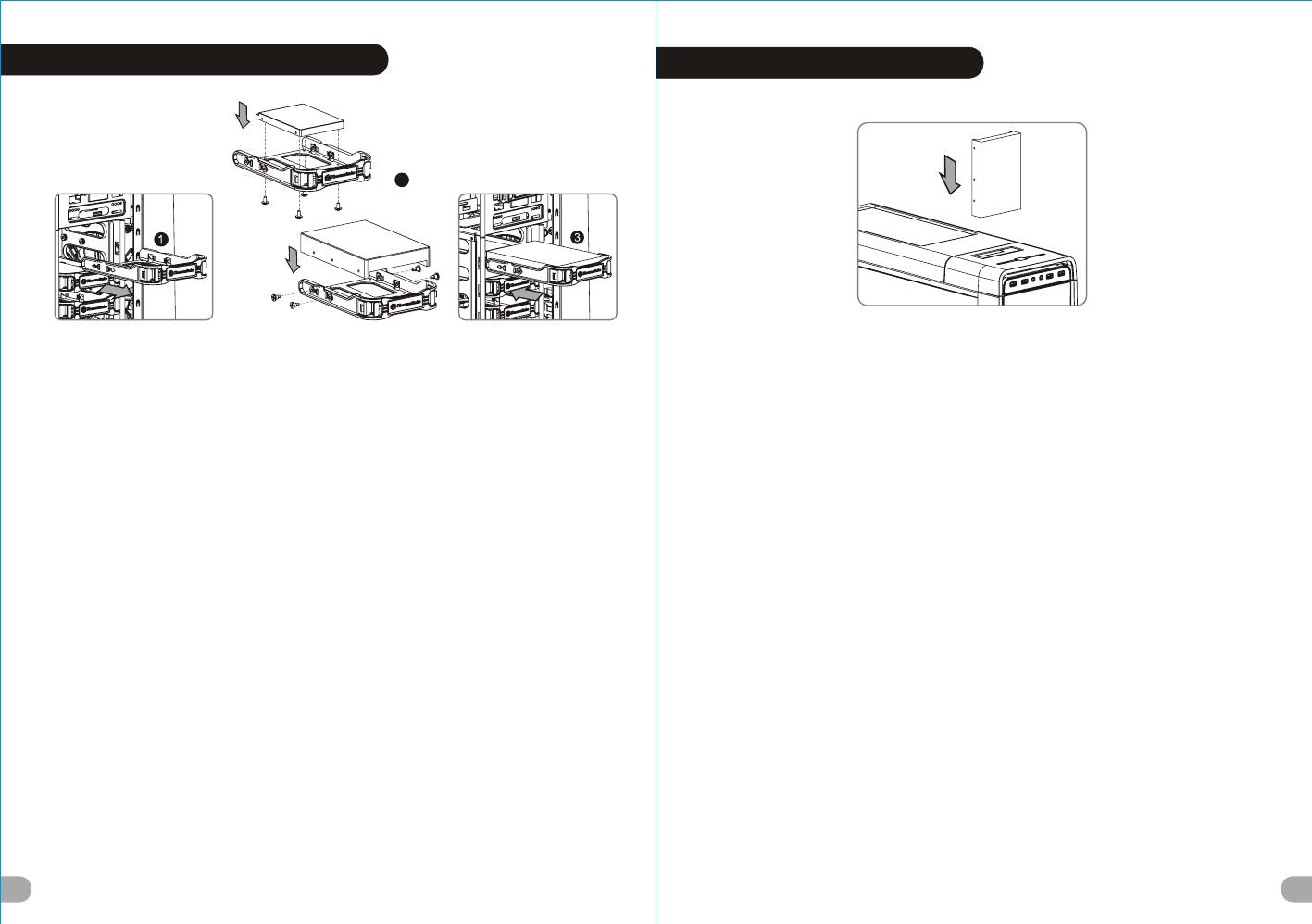
3.5” & 2.5” HDD Installation
12
2
3.5" HDD
2.5" HDD
English / 繁體中文 /
1. Pull the HDD tray out. 1. 將硬碟托盤取出
2. Place the 2.5” or 3.5” hard drive on the tray and 2. 將2.5”或3.5”硬碟放置在硬碟托盤上,用螺絲固定
secure it with screws. 硬碟
3. Slide the HDD tray back to the HDD cage. 3. 將硬碟托盤放回硬碟磁架中
Deutsch / 简体中文 /
1. Ziehen Sie den HD-Schacht heraus. 1. 将硬盘托盘取出
2. Montieren Sie die 2,5 oder 3,5 Zoll Festplatte im 2. 将2.5”或3.5”硬盘放置在硬盘托盘上,
Schacht und sichern Sie sie mit Schrauben.
用螺丝固定硬盘
3. Schieben Sie den Schacht wieder in den
3. 将硬盘托盘放回硬盘磁架中
Festplattenkäfig.
日本語 /
Français /
1.HDDトレイを引き出して外します。
1. Enlevez le boîtier du disque dur.
2.2.5インチHDD、SSD もしくは 3.5インチHDDド
2. Placez le disque dur de 2,5” ou de 3,5” dans le
ライブをトレイにネジで固定します。
boîtier et fixez-le avec des vis.
3. HDDトレイをHDDケージに戻します。
3. Refaites glisser le boîtier du disque dur dans la
cage de disques durs.
Русский /
1. Вытяните лоток для жестких дисков.
Español /
2. Установите 2,5- или 3,5-дюймовый жесткий
1. Extraiga la bandeja del disco duro.
диск в лоток и закрепите его винтами.
2. Coloque el disco duro de 2’5 ó 3'5” en la bandeja
3. Установите лоток для жестких дисков
y fíjelo con los tornillos.
обратно в каркас.
3. Vuelva a meter la bandeja del disco duro en su
hueco.
Türkçe /
1. HDD tepsisini dışarı çekin.
Italiano /
2. 2,5” veya 3,5” sabit disk sürücüsünü tepsinin
1. Estrarre il vano HDD.
üzerine yerleştirin ve vidalarla sabitleyin.
2. Posizionare il disco fisso da 2,5” o 3,5” nel vano
3. HDD tepsisini HDD kafesine geri yerleştirin.
e fissarlo con le viti.
3. Fare scorrere l’HDD indietro verso la struttura a
ภาษาไทย /
gabbia HDD.
1. ดึงถาด HDD ออกมา
2. วางฮาร์ดไดร์ฟขนาด 2.5” หรือ 3.5”
Português /
ลงบนถาดแล้วขันสกรูยึดให้แน่น
1. Puxe a bandeja do disco rígido para fora.
3. เลื่อนถาด HDD กลับเข้าในโครง HDD
2. Coloque o disco rígido de 2,5” ou 3,5” na bandeja
e fixe com parafusos.
3. Deslize a bandeja do disco rígido de volta para a
caixa do disco rígido.
HDD Docking Station
English /
The top HDD Docking slot is embedded to enable ultra fast transfer (up to 6.0Gbps) of large data to a SATA
hard disk without having to use an external storage enclosure. To ensure proper operation, please make sure
the following settings are correct:
- Ensure all required drivers are installed for your motherboard or SATA controller card.
- Connect the SATA cable to an available SATA connector on the motherboard or SATA controller card.
- Connect the power cable to power supply.
- Ensure AHCI (Advanced Host Controller Interface) is enabled on your motherboard or SATA controller card.
The AHCI enables for “hotswap” capability of the SATA hard drives without having to turn off the computer
prior to connecting or disconnecting of the hard drive. Please follow instruction provided
by your motherboard or SATA controller card to enable the AHCI function.
If you are using a brand new hard drive, the hard drive will need to be initialized (formatted) before it is
accessible. For more information on how to initialize (format) a new hard drive, please refer to the hard drive
user manual or visit
System running on Windows 7: http://www.thermaltakeusa.com/Faq.aspx?ID=1143
System running on Windows Vista: http://www.thermaltakeusa.com/Faq.aspx?ID=1079
System running on Windows XP: http://www.thermaltakeusa.com/Faq.aspx?ID=1073
Deutsch /
Der obere Einführungsschlitz der HDD-Dockingstation ist eingelassen, um einen ultraschnellen Transfer (bis
zu 6,0 GB/s) von umfangreichen Daten zur SATA-Festplatte zu ermögichen, ohne dafür ein externes Gehäuse
verwenden zu müssen. Um einen ordnungsgemäßen Betrieb zu gewährleisten, stellen Sie bitte sicher, dass
die folgenden Einstellungen richtig sind:
- Stellen Sie sicher, dass alle erforderlichen Treiber für Ihr Mainboard oder SATA Controller-Karte installiert
sind.
- Verbinden Sie das SATA-Kabel mit einen freien SATA-Anschluss auf dem Mainboard oder der SATA
Controller-Karte.
- Verbinden Sie das Stromkabel mit dem Netzteil.
- Stellen Sie sicher, dass AHCI (Advanced Host Controller Interface) auf dem Motherboard oder der SATA-
Controller-Karte aktiviert ist. AHCI ermöglicht die "HotSwap"-Funktion der SATA-Festplatten, ohne dass
Sie den Computer ausschalten müssen, bevor Sie die Festplatte anschließen oder entfernen. Bitte folgen
Sie den Anweisungen Ihres Motherboards oder der SATA-Controller-Karte, um die AHCI-Funktion zu
aktivieren.
Wenn Sie eine neue Festplatte benutzen, muss die Festplatte initialisiert werden (formatiert), bevor sie
nutzbar ist. Weitere Informationen darüber, wie man eine neue Festplatte formatiert, entnehmen Sie bitte
dem Benutzerhandbuch zur Festplatte oder besuchen Sie
System läuft unter Windows 7: http://www.thermaltakeusa.com/Faq.aspx?ID=1143
System läuft unter Windows Vista:http://www.thermaltakeusa.com/Faq.aspx?ID=1079
System läuft unter Windows XP: http://www.thermaltakeusa.com/Faq.aspx?ID=1073
藍色線條為尺寸標示,請勿印刷上去!
產品料號
V P 5 0 0 S e r i e s
U r b a n S 7 1 說明書 13 /03 /2 2 B
產品名稱
印刷項目
子件料號
發稿日期
版本
騎馬釘2 8 8 0
XXXXX
書寫紙
單色 無無
其他特殊處理效 果表面處理
2
厚度(g/m )
裝訂方式 材質頁數 印刷色彩
規格樣式
整本
MARKETING CHECK DESIGN
PRODUCT GM
其他特殊處理效 果表面處理
2
厚度(g/m )
材質印刷色彩
封面樣式(當封 面 與 內 頁 樣式不同時尚須填寫)
Poki
刀模線
125 mm
176 mm


