Installation Instructions
5
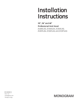
CONNECTING APPLIANCE USING 4-WIRE
CONNECTION (MUST BE USED FOR
MOBILE HOME INSTALLATION)
NOTES: SInce January 1,1996, the National Electric code
requires that the new constructions utilize a 4-wire
connection to an electric dryer.
WARNING:Only a 4-conductor cord shall be
used when the appliance is installed in a location where
grounding through the neutral conductor is prohibited.
Grounding through the neutral is prohibited for the new
branch-circuit installations, mobile homes, recreational
vehicles, and areas where local codes prohibit grounding
through the neutral conduction.
7XUQRȺWKHFLUFXLWEUHDNHUVDPSRUUHPRYHWKH
dryer’s circuit fuse at the electrical box.
%HVXUHWKHDSSOLDQFHFRUGLVXQSOXJJHGIURPWKHZDOO
receptacle.
5HPRYHWKHSRZHUFRUGFRYHUORFDWHGDWWKHORZHUEDFN
4. Remove and discard ground strap. Keep the green
ground screw for step 7.
,QVWDOOLQ8/UHFRJQL]HGVWUDLQUHOLHIWRSRZHUFRUG
HQWU\KROH%ULQJSRZHUFRUGWKURXJKVWUDLQUHOLHI
L1
N
L2
RELOCATE GREEN
GROUND SCREW
HERE
STRAIN
RELIEF
BRACKET
GREEN OR
YELLOW WIRE
3/4", UL
RECOGNIZED
STRAIN RELIEF
HOT
WIRE
SCREWS
(3)
HOT
WIRE
COVER
NEUTRAL
(White)
REMOVE GROUND STRAP
AND DISCARD. KEEP GREEN
GROUND SCREW
4 #10 AWG MINIMUM COPPER
CONDUCTORS OR 120/240V 30A POWER
SUPPLY CORD KIT MARKED FOR USE
WITH DRYERS & PROVIDED WITH
CLOSED LOOP OR SPADE TERMINALS
WITH UPTURNED ENDS (NOT SUPPLIED).
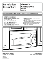
CONNECTING DRYER USING 3-WIRE
CONNECTION
3-wire Connection
1RWIRUXVHLQ&DQDGD
'2127XVHIRU0RELOH+RPH,QVWDOODWLRQV
127IRUXVHRQQHZFRQVWUXFWLRQ
127IRUXVHRQUHFUHDWLRQDOYHKLFOHV
127IRUXVHLQDUHDVZKHUHORFDOFRGHVSURKLELWJURXQGLQJ
through the neutral conduction.
7XUQ RȺ WKH FLUFXLW EUHDNHUV DPS RU UHPRYH WKH
dryer’s circuit fuse at the electrical box.
%HVXUHWKHappliance cord is unplugged from the wall.
5HPRYHWKHSRZHUFRUGFRYHUORFDWHGDWWKHORZHUEDFN
,QVWDOOLQ8/UHFRJQL]HGVWUDLQUHOLHIWRSRZHUFRUG
HQWU\KROH%ULQJSRZHUFRUGWKURXJKVWUDLQUHOLHI
L1
L2
STRAIN RELIEF
BRACKET
3/4", UL
RECOGNIZED
STRAIN RELIEF
HOT
WIRE
HOT
WIRE
GROUND
STRAP
GREEN
GROUND
SCREW
NEUTRAL
(White)
SCREWS
(3)
COVER
3 #10 AWG MINIMUM COPPER
CONDUCTORS OR 120/240V 30A POWER
SUPPLY CORD KIT MARKED FOR USE
WITH DRYERS & PROVIDED WITH CLOSED
LOOP OR SPADE TERMINALS WITH
UPTURNED ENDS (NOT SUPPLIED).
GROUNDING INSTRUCTIONS (Cont.)
Do not modify the plug provided with the appliance. If it
ZLOOQRW¿WWKH RXWOHW KDYHDSURSHURXWOHWLQVWDOOHGE\ D
TXDOL¿HGHOHFWULFLDQ
B.)RUGLUHFWZLUHFRQQHFWHGDSSOLDQFH
This appliance must be connected to a grounded, metal,
SHUPDQHQWZLULQJ V\VWHPRU DQHTXLSPHQWJURXQGLQJ
conductor must be run with the circuit conductors and
connected to the equipment grounding terminal or lead
on the appliance.
&RQQHFWSRZHUFRUGDVIROORZV
A. Connect the 2 hot lines to the outer screws of the
WHUPLQDOEORFNPDUNHG/DQG/
%&RQQHFWWKHQHXWUDOZKLWHOLQHWRWKHFHQWHURIWKH
WHUPLQDOEORFNPDUNHG1
%HVXUHJURXQGVWUDSLVFRQQHFWHGWRQHXWUDOFHQWHU
terminal of block and to green ground screw on cabinet
UHDU7LJKWHQDOOWHUPLQDOEORFNVFUHZVVHFXUHO\
7. Properly secure power cord to strain relief.
8. Reinstall the cover.
ELECTRICAL CONNECTION LOCATION
24” MODELS
27” MODELS
7(50,1$/
%/2&.
WARNING: NEVER LEAVE THE
COVER OFF OF THE TERMINAL BLOCK.