Broan-NuTone CF389 User manual
- Category
- Vacuum cleaners
- Type
- User manual

BUILT-IN
CENTRAL CLEANING SYSTEM
HOMEOWNER'S OPERATING INSTRUCTIONS
For Power Unit Models
VX475, VX550, VX1000, VX475C, VX550C, and VX1000C
Broan-NuTone LLC
Hartford, Wisconsin
www.nutone.com
888-336-3948
To register this product, visit www.nutone.com
30042318 rev. 09

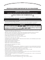
IMPORTANT SAFETY INSTRUCTIONS
SAVE THESE INSTRUCTIONS
READ ALL INSTRUCTIONS BEFORE USING THIS APPLIANCE
When using an electrical appliance, basic precautions should always be followed, including the following:
• Do not use on wet surfaces or outdoors.
• Do not allow to be used as a toy. Close attention is necessary when used by or near children.
• Use only as described in this manual. Use only manufacturer's recommended attachments.
• Do not put any object into openings. Do not use with any opening blocked; keep free of dust, lint, hair, and anything that may
reduce air flow.
• Keep hair, loose clothing, fingers and all parts of body away from openings and moving parts.
• Do not pick up anything that is burning or smoking, such as cigarettes, matches, or hot ashes.
• Do not use without dustbag or filter in place, depending on the model.
• Do not use to blow leaves or debris.
• Do not vacuum liquids or fine powders (such as drywall dust).
• Do not put any object on the unit.
• Ensure air flows freely to both side intake vents and exhausts unobstructed from top outlet.
• Do not install the unit horizontally.
• Do not use the pail as a wash bucket.
• Do not use the pail as a stool.
• Turn off all controls before unplugging.
• Use extra care when cleaning on stairs.
• Avoid picking up sharp objects.
• Do not use to pick up flammable or combustible liquids such as gasoline or use in areas where they may be present.
• Do not use with damaged cord or plug. If appliance is not working as it should, if it has been dropped, damaged, left
outdoors, or dropped into water, return it to a service center.
• Do not unplug the unit by pulling on cord. To unplug, grasp the plug, not the cord.
• Do not handle plug or appliance with wet hands.
• Connect to a properly grounded outlet only. See grounding instructions shown on page 11.
• Any servicing other than that recommended in this manual should be performed by an authorized service facility.
• We recommend that your unit be inspected by a specialized technician once a year.
• When performing installation, servicing or cleaning the unit, it is recommended to wear safety glasses and gloves.
2
CAUTION
On vacuum models VX475, VX550 and VX1000, DO NOT REMOVE either of the BOTTOM red cap plugs. Removing
these glued plugs will damage the unit. Only remove and use the outlets covered by the green TOP plugs. For VX475C
,
VX550C
& VX1000C models, DO NOT REMOVE either of the TOP red cap plugs that are glued to the unit. Removing
these glued plugs will damage the unit. Only remove and use the outlets covered by the green BOTTOM plugs.
WARNING
To reduce the risk of fire, electric shock, or injury:
!
FOR HOUSEHOLD USE ONLY
!
!

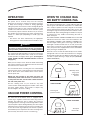
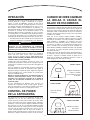
OPERATION
The power unit is located away from the everyday
living areas of your home—usually in the garage, basement,
or utility room. Through a network of strong, lightweight
tubing, the power unit connects to inlets strategically placed
throughout your home. To clean, attach cleaning tools to the
system's hose and insert the hose into an inlet. The system
is turned on by a power switch on the hose. As you vacuum,
dirt and dust are transported to the power unit where they
remain in a debris pail (depending on model type) until
emptied.
• This device has been evaluated by the appropriate
listing agencies and is intended for household use only.
The system status indicator light(s) on the front of the power
unit indicate that the power unit is ready for use. Under
normal operation, the light(s) will be green.
(A red light on
VX550, VX550C, VX1000 & VX1000C indicates a need to
empty pail.)
When you are ready to clean, attach the wand and cleaning
tool onto the end of the hose. Open the inlet cover and insert
the end of the hose into the inlet.
For non-switched hoses, inserting the hose automatically
turns the power unit on; removing the hose shuts the power
unit off. Some hoses have switches which can be used to
activate power unit.
NOTE: The inlet located on the power unit does not
automatically work when the hose is inserted. To turn
on the power unit inlet, use the rocker switch located on
the side of the power unit.
Use the cleaning tools as you would for any other
vacuum cleaner. Avoid picking up pine needles, coffee sticks
and other similar objects. These kinds of objects may
become lodged in the hose or tubing.
VACUUM POWER CONTROL
The wand end of the deluxe hoses is equipped with a
control ring to regulate suction. The control ring covers a
“bleeder” hole. Open the hole to reduce the suction for
cleaning draperies, small rugs, and other light fabrics. Some
very thick, plush carpets with high density yarns also require
reduced suction to make the nozzle easier to push. Be sure
to close the control ring completely over the hole to produce
the maximum power required for most other cleaning tasks.
(The economy hose does not have a control ring.)
WHEN TO CHANGE BAG
OR EMPTY DEBRIS PAIL
The VX475 and VX475C have a single indicator light that
remains green. This indicates that power is on and that the
unit is ready to operate. The level of bag fill for the VX475
can be determined by opening the direct door access and
checking the bag. The level of pail fill for the VX475C can be
determined by either viewing through the window on the pail
or releasing the carry handles and checking the level of
debris in the pail.
The VX550, VX550C, VX1000 & VX1000C all have the LED
indicator that shows the status of the level of debris in the
bag (VX550 & VX1000) or pail (VX550C & VX1000C). The
first three lights remain green as the bag or pail fills. The
fourth light is amber and will come on to alert you that the
bag or pail is nearly full. For the VX550 & VX1000 bagged
units, your power unit is equipped with sensors which detect
when your bag is completely full.
When this occurs, the unit will automatically turn off and the
red light will come on. Follow the instructions for changing
the bag and resetting the unit. When the fifth light turns red
it is time to replace the bag or empty the pail (CONTROL
PANEL DIAGRAM A).
3
WARNING
To avoid electric shock, never use hose and tools on a
wet surface. To avoid fire hazard, do not use vacuum to
pick up matches, fireplace ashes, or smoking material.
!
AC0002
CONTROL PANEL DIAGRAM A
GREEN AMBER RED RESET
VX550C & VX1000C
Timed pail
full recorder.
GREEN AMBER RED RESET
VX550 & VX1000
True bag full
pressure sensor.
GREEN ONLY
VX475 & VX 475C
Manually check
bag or pail
to determine
fill level.

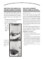
EMPTYING THE DEBRIS PAIL
(VX475C, VX550C & VX1000C)
Your power unit has a permanent filter that is self cleaning
under normal conditions. The filter protects the motor and
stops small dirt particles from escaping to the outside of the
power unit. The filter cleans itself by moving up when the
power unit starts, and dropping down when the unit is turned
off. The filter can be removed by means of a pull-tab for
cleaning if desired. Be sure to reinstall properly. Correct
placement is critical to insure proper protection for the
motor.
1. Release both carry handles on side of the unit by pulling
out and then pushing up. (FIGURE 1). Holding the pail by
the handles, lower it from unit (FIGURE 2).
2. Carry pail to trash receptacle and empty.
3. Reattach pail using handles.
4. Close door
and push
Reset
button
on control
panel. Light on
control panel
will change to
green on the
VX550 and
VX1000.
BAG REPLACEMENT
(VX475, VX550 & VX1000)
Under normal conditions the bag requires changing
approximately twice a year.
When the amber light on front of the VX550 or VX1000
power unit illuminates, it indicates that the soil bag has been
in use for 24 hours, and should be changed. Red light can
illuminate at any time indicating bag is full. When the red light
illuminates, it is absolutely necessary to change the bag. Red
light will turn off motor on bagged units, preventing
premature bag burst. If your installation uses indicating
inlets or indication hoses, the light on the interior faceplate
of the inlet will also have changed to amber at this time as a
reminder to change the bag in the power unit. Follow
directions below to change the bag. Once you have changed
the bag and replaced the debris pail, press the reset
button on the control panel. The first green light on the light
indicator will come on.
If you have been vacuuming large quantities of pet hair, etc.,
you may need to replace your bag more frequently. If you
notice a loss of vacuum prior to the light changing to amber,
check your disposable bag and replace as needed. If
changing the bag does not correct the loss of vacuum, see
Troubleshooting Guide section on pages 8-9.
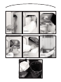
REMOVING A FULL BAG
1. Open the door on front of unit (FIGURE 3).
2. Lower bag holder by grasping tab and pulling out and
down (FIGURE 4). Holder will drop into bag removal
position (FIGURE 5).
3. Grasp top cardboard section of the full bag and slide bag
out approximately halfway until it detaches (FIGURE 6).
The dust trap at top of bag will automatically engage to
prevent any dust from escaping from bag. Slide bag
down and in and allow it to fall into debris pail (FIGURE 7).
4. Release both handles on each side of the unit by pulling
them out and pushing up. (FIGURE 8). Holding the pail
by the handles, lower it from unit.
5. Carry pail to trash receptacle and dispose of empty bag
(FIGURE 9).
4
FIGURE 1
FIGURE 2
Utility valve (circled
in FIGURE 2),
next to power
unit, can be used
to service area
around where
power unit is
installed.
Page is loading ...

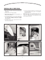
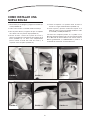
INSTALLING A NEW BAG
1. Open bag out at pleats and drop into detached pail
(FIGURE 10).
2. Reattach pail to unit using the handles.
3. Open the direct door and make sure bag holder is in
down position (FIGURE 11).
4. Reach bag through door access and slide cardboard tab
on to bag holder (FIGURE 12). Bag is fully engaged
when front edge of cardboard and holder are aligned
flush (FIGURE 13).
5. Lift holder back into place, bag will lock into place
automatically (FIGURE 14).
6. Close door and push
Reset
button on control panel. Light
on unit will change back to green on the VX550 &
VX1000 (FIGURE 15).
Replacement bags may be purchased from your local
NuTone Sales Outlet. For a NuTone Sales Outlet near you,
call toll free 1-800-543-8687 or visit www.nutone.com and
click on Dealer Locator tab.
6
FIGURE 10 FIGURE 11 FIGURE 12
FIGURE 13 FIGURE 14 FIGURE 15

7
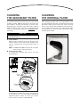
CLEANING
THE SECONDARY FILTER
A secondary safety filter, located at the top of the vacuum
chamber, provides additional protection to the motor. This
filter should be checked and cleaned if necessary, when
disposable bag is changed or when debris pail is emptied.
Simply brush filter clean. If the filter is excessively soiled,
wash in a mild detergent and let it dry completely
before
reinstalling.
A. FILTER REMOVAL
Open the door located on the front of the power unit.
Reach inside the unit and remove both locking sleeves
from the retaining hooks. Carefully pull filter down to
remove.
NOTE: VX1000 and VX1000C units have two secondary
filters. Ensure to remove both filters.
B. FILTER REINSTALLATION
To reinstall the secondary filter, reverse the steps
described above.
A replacement secondary filter (part no. 10941310) may
be purchased from your local NuTone independent
Authorized Service Center. To locate your nearest
Service Center, call toll free 1-888-336-3948.
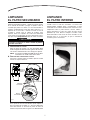
CLEANING
THE INTERNAL FILTER
When emptying the debris pail, it is recommended to clear
any dust and dirt that may have accumulated on the internal
filter media. Simply open the direct door, reach in and tap
the top of the internal filter (FIGURE 16). This will release
any loose debris into the pail. You may empty the pail again
at this point but it is not necessary as any amounts of dirt
and dust will be minimal.
CAUTION
Operating the power unit without the secondary filter
will void the warranty.
AO0066
SECONDARY
FILTER
RETAINING
HOOKS
LOCKING
SLEEVES
UNIT DOOR
FIGURE 16
Page is loading ...

9
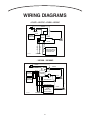
WIRING
This section refers to Figures 17 and 18.
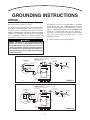
This appliance must be grounded. If it should malfunction or
break down, grounding provides a path of least resistance
for electric current, to reduce the risk of electric shock. This
appliance is equipped with a cord having an equipment-grounding
conductor and grounding plug. The plug must be plugged
into an appropriate outlet that is properly installed and
grounded in accordance with all local codes and ordinances.
This appliance is for use on a standard 120 V a.c., dedicated
20-amp branch circuit with a NEMA 5-20R receptacle for
VX475 and VX550 models. For VX1000 models a nominal
240 V a.c., dedicated 20-amp branch circuit with NEMA 6-20R
receptacle is required. Make sure that the appliance is
connected to an outlet and has a grounding attachment plug
that looks like the plug shown in either Figure 17 or 18,
depending on model.
No adapter should be used with this appliance.
TO
OTHER
INLETS
NOTE: INLET LEADS TO BE CONNECTED TO POWER UNIT
TERMINALS USING CRIMP
CONNECTORS AND LOW VOLTAGE
WIRE HARNESS
INLET
LEADS
MODEL V133 18/2 WIRE
POWER
UNIT
POWER
CORD
NORTH AMERICA
AC ELECTRIC
OUTLET
120 VOLT GROUNDED
OUTLET BOX
NEMA 5-20R
GROUND PIN
CRIMP CONNECTORS
LOW VOLTAGE WIRE
LOW VOLTAGE
WIRE HARNESS
AE0003A
VX475 & VX550 SERIES
FIGURE 17
TO
OTHER
INLETS
NOTE: INLET LEADS TO BE CONNECTED TO POWER UNIT
TERMINALS USING CRIMP
CONNECTORS AND LOW VOLTAGE
WIRE HARNESS
INLET
LEADS
MODEL V133 18/2 WIRE
POWER
UNIT
POWER
CORD
NORTH AMERICA
AC ELECTRIC
OUTLET
GROUND PIN
NEMA 6-20R
240 VOLT GROUNDED
OUTLET BOX
AE0004A
CRIMP CONNECTORS
LOW VOLTAGE WIRE
LOW VOLTAGE
WIRE HARNESS
VX1000 SERIES
FIGURE 18
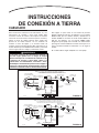
GROUNDING INSTRUCTIONS
WARNING
Improper connection of the equipment-grounding
conductor can result in a risk of electric shock. Check
with a qualified electrician or service person if you are
in doubt as to whether the outlet is properly grounded.
Do not modify the plug provided with the appliance—if
it will not fit the outlet, have a proper outlet installed by
a qualified electrician.
!

10
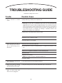
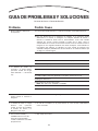
Trouble
1. Loss or decrease of vacuum
occurs.
2. Power unit does not start, or
shuts off during normal operation
with no LED showing red or
illuminated.
3. Power unit fails to stop when the
hose is removed.
4. Power unit shuts off during
normal operation, lights on unit,
wall valve and hose are all red.
5. For VX550 & VX1000 Series. All
lights on control panel flash
when unit is first plugged in.
Possible Cause
1a.Disposable bag or debris pail is completely full.
1b.Obstruction in the hose. A blockage in the hose can be determined by
inserting the hose into any wall inlet and, while power unit is running, check each
additional inlet for normal suction by holding the palm of your hand over the open
inlet. If normal suction is felt at all other inlets, insert the hose into a second inlet. If
the blockage still exists it is located in the hose. However, if the blockage does not
occur when the hose is changed, the blockage is probably located in the
tubing system leading to the original inlet.
1c. Obstruction in the tubing system inside the walls.
1d.Wall inlet cover not properly sealed.
1e.Exhaust tubing or vent clogged.
2a.Defective inlet. Check other wall inlets.
2b.Thermoprotector has been activated OR there is a tripped circuit breaker on the
unit.
2c. Blown fuse or tripped circuit breaker on house electrical panel.
2d.Defective hose.
2e.Microprocessor lockup.
NOTE: This applies only to the VX550 & VX1000 Series.
2f. Low-line voltage.
3. An electrical short in the low voltage control line.
4. Bag full sensing has been activated. Disposable bag is competely full.
5. Low-line voltage.
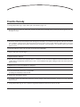
TROUBLESHOOTING GUIDE
Read before calling Service Center

11
Possible Remedy
1a.Change disposable bag or empty debris pail as described in pages 4-5.
1b.Insert handle end of hose into utility valve at power unit. Turn unit on. This will reverse normal air flow through the hose and
dislodge any clogs.
1c. Insert hose end into any inlet with power unit running, place the palm of your hand over the opposite end of the hose. When
you can feel the suction increase, hold your hand over the hose end for a few seconds and then quickly remove your hand.
This procedure repeated several times should clear the obstruction. If the blockage is not cleared, contact your nearest
Service Center.
1d.Check all wall inlet covers to be sure they are closed and sealed tightly.
1e.Inspect and remove any blockages.
2a.Replace defective wall inlet.
2b.Turn unit off for 20 minutes then plug unit back in. If unit does not start, look for the tripped circuit breaker behind the unit,
a white button has popped up, push it back to reset it. If circuit breaker trips again, unplug your unit and contact your local
Service Center.
2c. Replace fuse or reset circuit breaker on wall panel.
2d.Replace hose as required.
2e.1) Push
Reset
button while unit is engaged OR
2) Unplug unit completely for 60 seconds.
2f. Contact your local Service Center.
3. A complete check of all wall inlets and power unit low voltage control lead connections. Contact your local authorized
Service Center.
4. Change disposable bag. Be sure to push the bag full
Reset
button located on the front of the unit.
5. Contact your local authorized Service Center.

12
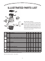
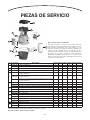
ILLUSTRATED PARTS LIST
Order service parts by “Part No.” - not by “Key No.”
Key No. Part No. Description VX475 VX550 VX1000 VX475C VX550C VX1000C
1
10941189 Pail assembly VS X X
10941191 Pail assembly TS X X X X
2 10941190 Door assembly X X X X X X
3 10941199 Latch kit (with screws) X X X X X X
4
10941232 VS PCB’s assembly (including mother, daughter and screws)* X X
10941233 TS1 PCB’s assembly (including mother, daughter and screws)* X X
10941195 TS2 PCB’s assembly (including mother, daughter and screws)* X X
5
10941235 VS motor with motor harness, fuse with fuse harness and circuit breaker* X X
10941236 TS1 motor with motor harness, fuse with fuse harness and circuit breaker* X X
10941231 TS2 motor with motor harness, fuse with fuse harness and circuit breaker* X X
6
30100528 Pail gasket TS X X X X
30100527 Pail gasket VS X X
7
30010272 Cyclonic filter VS X
30010270 Cyclonic filter TS X X
8
10941215 Motor chamber VS with logo* X X
10941216 Motor chamber TS with logo* X X X X
9
10941212 Top cap VS with logo X X
10941214 Top cap TS with logo X X X X
10 30111112 Mount bag plate X X X
11
VX3918 Filter bag ass’y TS (3 per pack) X X
VX3916 Filter bag ass’y VS X
*This part MUST be removed and installed by a qualified technician.
9
8
4
2
5
6
7
1
11
3
10
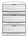
REPLACEMENT PARTS AND REPAIR
In order to ensure your unit remains in good working condition,
you must use Broan-NuTone genuine replacement parts only.
Broan-NuTone genuine replacement parts are specially designed
for each unit and are manufactured to comply with all the
applicable certification standards and maintain a high standard of
safety. Any third party replacement part used may cause serious
damage and drastically reduce the performance level of your
unit, which will result in premature failing. Broan-NuTone also
recommends to contact a Broan-NuTone certified service depot
for all replacement parts and repairs.

Eight-Year Limited Warranty
WARRANTY OWNER: NuTone warrants to the original consumer purchaser of its products that such products will be free from defects in materials and workmanship for a
period of eight (8) years from the date of original purchase. T
HERE ARE NO OTHER WARRANTIES, EXPRESSED OR IMPLIED, INCLUDING, BUT NOT LIMITED TO, IMPLIED WARRANTIES OF
MERCHANTABILITY OR FITNESS FOR A PARTICULAR PURPOSE
.
During this time period, NuTone will, at its option, repair or replace, without charge, any product or part which is found to be defective under normal use and service. T
HIS
WARRANTY DOES NOT EXTEND TO FLUORESCENT LAMP STARTERS OR TUBES
, FILTERS, DUCT, ROOF CAPS, WALL CAPS AND OTHER ACCESSORIES FOR DUCTING. This warranty does not cover
(a) normal maintenance and service or (b) any products or parts which have been subject to misuse, negligence, accident, improper maintenance or repair (other than by
NuTone), faulty installation or installation contrary to recommended installation instructions.
The duration of any implied warranty is limited to the eight-year period as specified for the express warranty. Some states do not allow limitation on how long an implied
warranty lasts, so the above limitation may not apply to you.
N
UTONE’S OBLIGATION TO REPAIR OR REPLACE, AT NUTONE’S OPTION, SHALL BE THE PURCHASER'S SOLE AND EXCLUSIVE REMEDY UNDER THIS WARRANTY. NUTONE SHALL NOT BE LIABLE FOR
INCIDENTAL
, CONSEQUENTIAL OR SPECIAL DAMAGES ARISING OUT OF OR IN CONNECTION WITH PRODUCT USE OR PERFORMANCE. Some states do not allow the exclusion or limitation of
incidental or consequential damages, so the above limitation or exclusion may not apply to you. This warranty gives you specific legal rights, and you may also have other
rights, which vary from state to state. This warranty supersedes all prior warranties.
W
ARRANTY SERVICE: To qualify for warranty service, you must (a) notify NuTone at the address stated below or telephone 1-800-543-8687, (b) give the model number
and part identification and (c) describe the nature of any defect in the product or part. At the time of requesting warranty service, you must present evidence of
the original purchase date.
Date of Installation Builder or Installer
Model Number and Product Description
IF YOU NEED ASSISTANCE OR SERVICE: For the location of your nearest NuTone independent Authorized Service Center:
Residents of the contiguous United States Dial Free: 1-800-543-8687
Please be prepared to provide: Product model number • Date and proof of purchase • The nature of the difficulty
Residents of Alaska or Hawaii should write to: NuTone Inc. Attn: Department of National Field Service, 926 West State Street, Hartford, WI 53027
Four-Year Limited Warranty
WARRANTY OWNER: NuTone warrants to the original consumer purchaser of its products that such products will be free from defects in materials and workmanship for a
period of four (4) years from the date of original purchase. T
HERE ARE NO OTHER WARRANTIES, EXPRESSED OR IMPLIED, INCLUDING, BUT NOT LIMITED TO, IMPLIED WARRANTIES OF
MERCHANTABILITY OR FITNESS FOR A PARTICULAR PURPOSE
.
During this time period, NuTone will, at its option, repair or replace without charge, any product or part which is found to be defective under normal use and service. T
HIS
WARRANTY DOES NOT EXTEND TO FLUORESCENT LAMP STARTERS OR TUBES
, FILTERS, DUCT, ROOF CAPS, WALL CAPS AND OTHER ACCESSORIES FOR DUCTING. This warranty does not cover
(a) normal maintenance and service or (b) any products or parts which have been subject to misuse, negligence, accident, improper maintenance or repair (other than by
NuTone), faulty installation or installation contrary to recommended installation instructions.
The duration of any implied warranty is limited to the four-year period as specified for the express warranty. Some states do not allow limitation on how long an implied
warranty lasts, so the above limitation may not apply to you.
N
UTONE’S OBLIGATION TO REPAIR OR REPLACE, AT NUTONE’S OPTION, SHALL BE THE PURCHASER'S SOLE AND EXCLUSIVE REMEDY UNDER THIS WARRANTY. NUTONE SHALL NOT BE LIABLE FOR
INCIDENTAL
, CONSEQUENTIAL OR SPECIAL DAMAGES ARISING OUT OF OR IN CONNECTION WITH PRODUCT USE OR PERFORMANCE. Some states do not allow the exclusion or limitation of
incidental or consequential damages, so the above limitation or exclusion may not apply to you. This warranty gives you specific legal rights, and you may also have other
rights, which vary from state to state. This warranty supersedes all prior warranties.
W
ARRANTY SERVICE: To qualify for warranty service, you must (a) notify NuTone at the address stated below or telephone 1-800-543-8687, (b) give the model number
and part identification and (c) describe the nature of any defect in the product or part. At the time of requesting warranty service, you must present evidence of
the original purchase date.
Date of Installation Builder or Installer
Model Number and Product Description
IF YOU NEED ASSISTANCE OR SERVICE: For the location of your nearest NuTone Independent Authorized Service Center:
Residents of the contiguous United States Dial Free: 1-800-543-8687
Please be prepared to provide: Product model number • Date and proof of purchase • The nature of the difficulty
Residents of Alaska or Hawaii should write to: NuTone Inc. Attn: Department of National Field Service, 926 West State Street, Hartford, WI 53027
13
Two-Year Limited Warranty
W
ARRANTY OWNER: NuTone warrants to the original consumer purchaser of its products that such products will be free from defects in materials and workmanship for a
period of two (2) years from the date of original purchase. T
HERE ARE NO OTHER WARRANTIES, EXPRESSED OR IMPLIED, INCLUDING, BUT NOT LIMITED TO, IMPLIED WARRANTIES OF
MERCHANTABILITY OR FITNESS FOR A PARTICULAR PURPOSE
.
During this time period, NuTone will, at its option, repair or replace without charge, any product or part which is found to be defective under normal use and service.
THIS
WARRANTY DOES NOT EXTEND TO FLUORESCENT LAMP STARTERS OR TUBES
, FILTERS, DUCT, ROOF CAPS, WALL CAPS AND OTHER ACCESSORIES FOR DUCTING. This warranty does
not cover (a) normal maintenance and service or (b) any products or parts which have been subject to misuse, negligence, accident, improper maintenance or repair (other
than by NuTone), faulty installation or installation contrary to recommended installation instructions.
The duration of any implied warranty is limited to the two-year period as specified for the express warranty. Some states do not allow limitation on how long an implied
warranty lasts, so the above limitation may not apply to you.
NUTONE’S OBLIGATION TO REPAIR OR REPLACE, AT NUTONE’S OPTION, SHALL BE THE PURCHASER'S SOLE AND EXCLUSIVE REMEDY UNDER THIS WARRANTY. NUTONE SHALL NOT
BE LIABLE FOR INCIDENTAL
, CONSEQUENTIAL OR SPECIAL DAMAGES ARISING OUT OF OR IN CONNECTION WITH PRODUCT USE OR PERFORMANCE. Some states do not allow the
exclusion or limitation of incidental or consequential damages, so the above limitation or exclusion may not apply to you. This warranty gives you specific legal rights, and
you may also have other rights, which vary from state to state. This warranty supersedes all prior warranties.
W
ARRANTY SERVICE: To qualify for warranty service, you must (a) notify NuTone at the address stated below or telephone 1-800-543-8687, (b) give the model number
and part identification and (c) describe the nature of any defect in the product or part. At the time of requesting warranty service, you must present evidence of
the original purchase date.
Date of Installation Builder or Installer
Model Number and Product Description
IF YOU NEED ASSISTANCE OR SERVICE: For the location of your nearest NuTone Independent Authorized Service Center:
Residents of the contiguous United States Dial Free: 1-800-543-8687
Please be prepared to provide: Product model number • Date and proof of purchase • The nature of the difficulty
Residents of Alaska or Hawaii should write to: NuTone Inc. Attn: Department of National Field Service, 926 West State Street, Hartford, WI 53027
For Models VX1000 & VX1000C
For Models VX550 & VX550C
For Models VX475 & VX475C
Rev. 06/2009
Rev. 06/2009
Rev. 06/2009

14
WARRANTY
All VX power units are covered by a NuTone 2, 4, or 8-year warranty. Refer to your model number for which
warranty you have. Tools and accessories warranted for 1 year from date of purchase. See page 13 for details.
Product specifications subject to change without notice.
926 WEST STATE STREET, HARTFORD, WI 53027
WWW.NUTONE.COM

SISTEMA INCORPORADO
DE LIMPIEZA CENTRAL
INSTRUCCIONES DE OPERACION PARA
LOS PROPIETARIOS
Para modelos de unidades de poder
VX475, VX550, VX1000, VX475, VX475C, VX550C, VX1000C
Broan-NuTone LLC
Hartford, Wisconsin
www.nutone.com
888-336-3948
Para registrar este producto, visite a www.nutone.com
30042318 rev. 09
Page is loading ...
Page is loading ...
Page is loading ...
Page is loading ...
Page is loading ...
Page is loading ...

8
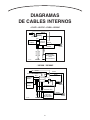
DIAGRAMAS
DE CABLES INTERNOS
• VX475 • VX475C • VX550 • VX550C
AE0025E
BLANCO
BLANCO
NEGRO
NEGRO
NEGRO
NEGRO
VERDE
VERDE
120 VOLTIOS
MOTOR
CONTROL
AMARILLO
AMARILLO
PRESOSTATO
UNIDAD DE PODER
VX550
SÓLO CON BOLSA
PROTECCIÓN
TÉRMICA
PLACA DE
CONTROL
AZUL
AZUL
AE0026E
ROJO O BLANCO
ROJO O BLANCO
ROJO O BLANCO
NEGRO
NEGRO
NEGRO
NEGRO
AZUL
NEGRO
NEGRO
VERDE
VERDE
VERDE
VERDE
AMARILLO
AMARILLO
MOTOR
MOTOR
CONTROL
PLACA DE
CONTROL
PROTECCIÓN
TÉRMICA
240 VOLTIOS
PRESOSTATO
UNIDAD DE
PODER VX1000
SÓLO CON BOLSA
AZUL
AZUL
AZUL
PROTECCIÓN
TÉRMICA
• VX1000 • VX1000C
Page is loading ...
Page is loading ...
Page is loading ...
Page is loading ...
Page is loading ...
Page is loading ...
-
 1
1
-
 2
2
-
 3
3
-
 4
4
-
 5
5
-
 6
6
-
 7
7
-
 8
8
-
 9
9
-
 10
10
-
 11
11
-
 12
12
-
 13
13
-
 14
14
-
 15
15
-
 16
16
-
 17
17
-
 18
18
-
 19
19
-
 20
20
-
 21
21
-
 22
22
-
 23
23
-
 24
24
-
 25
25
-
 26
26
-
 27
27
-
 28
28


Broan-NuTone CF389 User manual
- Category
- Vacuum cleaners
- Type
- User manual
Ask a question and I''ll find the answer in the document
Finding information in a document is now easier with AI
in other languages
- español: Broan-NuTone CF389 Manual de usuario
Related papers
Other documents
-
Broan Vacuum Cleaner VX12000C User manual
-
NuTone VX1040CC Operating Instructions Manual
-
NuTone VX550C User manual
-
-
Electrolux Afuera User manual
-
-
-
-
NuTone VX550 Installation Instructions Manual
-