
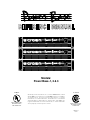
Models:
Power Base-1, 2 & 3
OFF
POWER
OFF
POWER
OFF
POWER
© 1996 by Crown International, Inc., P.O. Box 1000, Elkhart, Indiana
46515-1000 U.S.A. Telephone: 219-294-8000. Power-Tech amplifiers
are produced by the Professional Audio Division of Crown
International, Inc. Trademark Notice:
Power Base-3
™
is a trademark
and
Power Base-1
®
, Power Base-2
®
, Crown
,
®
IOC
®
and
ODEP
®
are
registered trademarks of Crown International, Inc. Other trademarks
are the property of their respective owners.
™
®
E106377
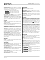
Applies only to 120 VAC,
North American PB-1,
PB-2 and PB-3 units.
101229-1
12/96
Applies only to 120 VAC,
North American PB-1
and PB-2 units.
®
LL 32521C

WORLDWIDE
SUMMARY OF WARRANTY
The Crown Audio Division of Crown International, Inc., 1718 West
Mishawaka Road, Elkhart, Indiana 46517-4095 U.S.A. warrants to you, the
ORIGINAL PURCHASER and ANY SUBSEQUENT OWNER of each
NEW Crown
1
product, for a period of three (3) years from the date of
purchase by the original purchaser (the “warranty period”) that the new
Crown product is free of defects in materials and workmanship, and we
further warrant the new Crown product regardless of the reason for failure,
except as excluded in this Crown Warranty.
1
Note: If your unit bears the name “Amcron,” please substitute it for the
name “Crown” in this warranty.
ITEMS EXCLUDED FROM THIS CROWN WARRANTY
This Crown Warranty is in effect only for failure of a new Crown product
which occurred within the Warranty Period. It does not cover any product
which has been damaged because of any intentional misuse, accident,
negligence, or loss which is covered under any of your insurance contracts.
This Crown Warranty also does not extend to the new Crown product if the
serial number has been defaced, altered, or removed.
WHAT THE WARRANTOR WILL DO
We will remedy any defect, regardless of the reason for failure (except as
excluded), by repair, replacement, or refund. We may not elect refund
unless you agree, or unless we are unable to provide replacement, and
repair is not practical or cannot be timely made. If a refund is elected, then
you must make the defective or malfunctioning product available to us free
and clear of all liens or other encumbrances. The refund will be equal to the
actual purchase price, not including interest, insurance, closing costs, and
other finance charges less a reasonable depreciation on the product from
the date of original purchase. Warranty work can only be performed at our
authorized service centers. We will remedy the defect and ship the product
from the service center within a reasonable time after receipt of the
defective product at our authorized service center. All expenses in
remedying the defect, including surface shipping costs to the nearest
authorized service center, will be borne by us. (You must bear the expense
of all taxes, duties and other customs fees when transporting the product.)
HOW TO OBTAIN WARRANTY SERVICE
You must notify us of your need for warranty service not later than ninety
(90) days after expiration of the warranty period. All components must be
shipped in a factory pack. Corrective action will be taken within a
reasonable time of the date of receipt of the defective product by our
authorized service center. If the repairs made by our authorized service
center are not satisfactory, notify our authorized service center
immediately.
DISCLAIMER OF CONSEQUENTIAL AND INCIDENTAL DAMAGES
YOU ARE NOT ENTITLED TO RECOVER FROM US ANY INCIDENTAL
DAMAGES RESULTING FROM ANY DEFECT IN THE NEW CROWN
PRODUCT. THIS INCLUDES ANY DAMAGE TO ANOTHER PRODUCT
OR PRODUCTS RESULTING FROM SUCH A DEFECT.
WARRANTY ALTERATIONS
No person has the authority to enlarge, amend, or modify this Crown
Warranty. This Crown Warranty is not extended by the length of time which
you are deprived of the use of the new Crown product. Repairs and
replacement parts provided under the terms of this Crown Warranty shall
carry only the unexpired portion of this Crown Warranty.
DESIGN CHANGES
We reserve the right to change the design of any product from time to time
without notice and with no obligation to make corresponding changes in
products previously manufactured.
LEGAL REMEDIES OF PURCHASER
No action to enforce this Crown Warranty shall be commenced later than
ninety (90) days after expiration of the warranty period.
THIS STATEMENT OF WARRANTY SUPERSEDES ANY OTHERS
CONTAINED IN THIS MANUAL FOR CROWN PRODUCTS.
9/90
NORTH AMERICA
SUMMARY OF WARRANTY
The Crown Audio Division of Crown International, Inc., 1718 West Mishawaka
Road, Elkhart, Indiana 46517-4095 U.S.A. warrants to you, the ORIGINAL
PURCHASER and ANY SUBSEQUENT OWNER of each NEW Crown product,
for a period of three (3) years from the date of purchase by the original purchaser
(the “warranty period”) that the new Crown product is free of defects in materials
and workmanship. We further warrant the new Crown product regardless of the
reason for failure, except as excluded in this Warranty.
ITEMS EXCLUDED FROM THIS CROWN WARRANTY
This Crown Warranty is in effect only for failure of a new Crown product which
occurred within the Warranty Period. It does not cover any product which has
been damaged because of any intentional misuse, accident, negligence, or loss
which is covered under any of your insurance contracts. This Crown Warranty
also does not extend to the new Crown product if the serial number has been
defaced, altered, or removed.
WHAT THE WARRANTOR WILL DO
We will remedy any defect, regardless of the reason for failure (except as
excluded), by repair, replacement, or refund. We may not elect refund unless you
agree, or unless we are unable to provide replacement, and repair is not practical
or cannot be timely made. If a refund is elected, then you must make the defective
or malfunctioning product available to us free and clear of all liens or other
encumbrances. The refund will be equal to the actual purchase price, not
including interest, insurance, closing costs, and other finance charges less a
reasonable depreciation on the product from the date of original purchase.
Warranty work can only be performed at our authorized service centers or at the
factory. We will remedy the defect and ship the product from the service center
or our factory within a reasonable time after receipt of the defective product at our
authorized service center or our factory. All expenses in remedying the defect,
including surface shipping costs in the United States, will be borne by us. (You
must bear the expense of shipping the product between any foreign country and
the port of entry in the United States and all taxes, duties, and other customs fees
for such foreign shipments.)
HOW TO OBTAIN WARRANTY SERVICE
You must notify us of your need for warranty service not later than ninety (90)
days after expiration of the warranty period. All components must be shipped in
a factory pack, which, if needed, may be obtained from us free of charge.
Corrective action will be taken within a reasonable time of the date of receipt of
the defective product by us or our authorized service center. If the repairs made
by us or our authorized service center are not satisfactory, notify us or our
authorized service center immediately.
DISCLAIMER OF CONSEQUENTIAL AND INCIDENTAL DAMAGES
YOU ARE NOT ENTITLED TO RECOVER FROM US ANY INCIDENTAL
DAMAGES RESULTING FROM ANY DEFECT IN THE NEW CROWN
PRODUCT. THIS INCLUDES ANY DAMAGE TO ANOTHER PRODUCT OR
PRODUCTS RESULTING FROM SUCH A DEFECT. SOME STATES DO
NOT ALLOW THE EXCLUSION OR LIMITATIONS OF INCIDENTAL OR
CONSEQUENTIAL DAMAGES, SO THE ABOVE LIMITATION OR
EXCLUSION MAY NOT APPLY TO YOU.
WARRANTY ALTERATIONS
No person has the authority to enlarge, amend, or modify this Crown Warranty.
This Crown Warranty is not extended by the length of time which you are
deprived of the use of the new Crown product. Repairs and replacement parts
provided under the terms of this Crown Warranty shall carry only the unexpired
portion of this Crown Warranty.
DESIGN CHANGES
We reserve the right to change the design of any product from time to time without
notice and with no obligation to make corresponding changes in products
previously manufactured.
LEGAL REMEDIES OF PURCHASER
THIS CROWN WARRANTY GIVES YOU SPECIFIC LEGAL RIGHTS, YOU
MAY ALSO HAVE OTHER RIGHTS WHICH VARY FROM STATE TO STATE.
No action to enforce this Crown Warranty shall be commenced later than ninety
(90) days after expiration of the warranty period.
THIS STATEMENT OF WARRANTY SUPERSEDES ANY OTHERS
CONTAINED IN THIS MANUAL FOR CROWN PRODUCTS.
9/90
Telephone: 219-294-8200. Facsimile: 219-294-8301
Telephone: 219-294-8200. Facsimile: 219-294-8301
THREE YEAR
FULL WARRANTY
YEAR
3
YEAR
3

Printed on
recycled paper.
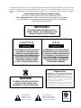
The lightning bolt
triangle is used to
alert the user to the
risk of electric shock.
The exclamation point
triangle is used to alert the
user to important operating
or maintenance instructions.
WARNING
TO REDUCE THE RISK OF ELECTRIC
SHOCK, DO NOT EXPOSE THIS
EQUIPMENT TO RAIN OR MOISTURE!
Magnetic Field
CAUTION! Do not locate sensitive high-gain
equipment such as preamplifiers or tape decks
directly above or below the unit. Because this
amplifier has a high power density, it has a strong
magnetic field which can induce hum into unshielded
devices that are located nearby. The field is stron-
gest just above and below the unit.
If an equipment rack is used, we recommend locat-
ing the amplifier(s) in the bottom of the rack and the
preamplifier or other sensitive equipment at the top.
IMPORTANT
THE POWER BASE-3 REQUIRES CLASS 1
OUTPUT WIRING. THE POWER BASE-1 AND
2 REQUIRE CLASS 2 OUTPUT WIRING.
The information furnished in this manual does not include all of the details of design, production, or variations of the
equipment. Nor does it cover every possible situation which may arise during installation, operation or mainte-
nance. If you need special assistance beyond the scope of this manual, please contact our Technical Support
Group.
Crown Audio Division Technical Support Group
Plant 2 SW, 1718 W. Mishawaka Rd., Elkhart, Indiana 46517 U.S.A.
Phone: 800-342-6939 (North America, Puerto Rico and Virgin Islands) or 219-294-8200
Fax: 219-294-8301 Fax Back: 800-294-4094 (North America only) or 219-293-9200
Internet: http://www.crownintl.com
C A U T I O N
RISK OF ELECTRIC SHOCK
DO NOT OPEN
TO PREVENT ELECTRIC SHOCK DO
NOT REMOVE TOP OR BOTTOM
COVERS. NO USER SERVICEABLE
PARTS INSIDE. REFER SERVICING TO
QUALIFIED SERVICE PERSONNEL.
DISCONNECT POWER CORD BE-
FORE REMOVING BACK PANEL
COVER TO ACCESS GAIN SWITCH.
A V I S
RISQUE DE CHOC ÉLECTRIQUE
N’OUVREZ PAS
À PRÉVENIR LE CHOC ÉLECTRIQUE
N’ENLEVEZ PAS LES COUVERCLES. IL
N’Y A PAS DES PARTIES SERVICEABLE
À L’INTÉRIEUR. TOUS REPARATIONS
DOIT ETRE FAIRE PAR PERSONNEL
QUALIFIÉ SEULMENT. DÉBRANCHER
LA BORNE AVANT D’ENLEVER LA
COVERTURE EN ARRIÈRE.

Power Base Series Power Amplifiers
Page 4
CONTENTS
1 Welcome .......................................................................... 7
1.1 Unpacking ................................................................. 7
1.2 Features .................................................................... 7
2 Installation ....................................................................... 9
2.1 Stereo ........................................................................ 9
2.2 Mono ......................................................................... 9
2.3 Input Sensitivity Adjustment...................................... 10
2.4 Additional Load Protection ....................................... 10
2.5 Required AC Mains .................................................. 10
3 Operation ....................................................................... 11
3.1 Precautions .............................................................. 11
3.2 Power Indicator ........................................................ 11
3.3 Protection Systems ................................................... 11
3.3.1
ODEP ............................................................
11
3.3.2 Ultrasonic and RF Protection .......................... 11
3.3.3 Drive Protection ............................................. 11
3.3.4 Transformer Thermal Protection ..................... 12
3.3.5 Fuses and Circuit Breakers ............................ 12
3.4 Controls ................................................................... 12
3.5 Filter Cleaning .......................................................... 12
4 Specifications ................................................................ 13
5 Accessories ................................................................... 19
5.1 MT-XLR .................................................................... 19
5.2 MT-BB ..................................................................... 19
6 Service ........................................................................... 20
6.1 Worldwide Service ................................................... 20
6.2 North American Service ........................................... 20
6.2.1 Service at a North American Service Center ... 20
6.2.2 Factory Service .............................................. 20

Power Base Series Power Amplifiers
Page 5
ILLUSTRATIONS
1.1 Power Base Front and Back Panels .................................... 7
2.1Three System Connection Methods ....................................... 8
2.2Do NOT Block Air Flow .......................................................... 9
2.3Power Base Input Wiring ....................................................... 9
2.4Input Sensitivity Switch ........................................................ 10
2.5Loudspeaker Fuse Nomograph ........................................... 10
3.1Back Panel Level Controls ................................................... 12
4.1Power Base-1 Minimum Power Matrix .................................. 15
4.2Power Base-2 Minimum Power Matrix .................................. 16
4.3Power Base-3 Minimum Power Matrix .................................. 16
4.4Power Base-1 Maximum Power Matrix ................................. 17
4.5Power Base-2 Maximum Power Matrix ................................. 18
4.6Power Base-3 Maximum Power Matrix ................................. 18
5.1The MT-XLR ........................................................................ 19
5.2The MT-BB .......................................................................... 19

Power Base Series Power Amplifiers
Page 6

Power Base Series Power Amplifiers
Page 7
1 Welcome
Congratulations on choosing a
Power Base
amplifier.
Power Base
amplifiers are compact, professional ste-
reo power amplifiers engineered to meet the most de-
manding sound reinforcement needs. They compare
very favorably to more expensive amplifiers, providing
uncolored sound and signal-to-noise ratios commonly
associated with recording studios.
This manual will help you successfully install and use
your amplifier—we strongly recommend you read all
instructions, warnings and cautions. If you plan to oper-
ate in one of the two mono modes, be sure to read Sec-
tion 2.2. Also for your protection, please save your bill
of sale as it is your official proof of purchase.
1.2 Features
❏ Rugged, professional power amplifier built for the road.
Mounts in a standard 19 inch (48.3 cm) rack.
❏ Crown’s patented
grounded bridge
circuitry gener-
ates large voltage swings while avoiding electrical
stress on the output stages. This results in low distortion
and high reliability.
❏ Front panel power switch with turn-on delay for loud-
speaker protection.
❏ Patented Output Device Emulation Protection (
ODEP
®
)
keeps the amplifier working when others would fail.
❏ High damping factor provides superior control over low
frequency drivers for a clean, accurate low end.
❏ Safe with any load. Bridge-Mono and Parallel-Mono
modes offer optimal load-matching performance.
❏ Complete protection against shorted outputs, mis-
matched loads, overheating, DC input/output and high-
frequency overload; full internal fault protection.
❏ Balanced phone jack inputs with internal three-position
sensitivity switch. Optional XLR or barrier block input
connectors are available with the
MT-XLR
or
MT-BB
ac-
cessories.
❏ Ground lift switch is provided to isolate the chassis
ground from the phone jack input ground.
❏ Efficient heat sinks and self-contained forced air cool-
ing system dissipate heat quickly and evenly for extra
amplifier protection and greater power output.
❏ Three year “No-Fault” full warranty and guaranteed
specifications protect your investment.
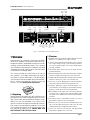
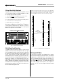
Fig. 1.1 Power Base Front and Back Panels
CAUTION:
THIS COVER IS NECESSARY FOR
EFFICIENT COOLING OF THE AMPLIFIER.
REMOVE ONLY TO ACCESS GAIN SWITCH.
REG. U.S. PAT. OFF.
4,330,809
4,611,180
CAUTION:
TURN OFF AMPLIFIER
BEFORE CHANGING THIS SWITCH!
STEREO
BRIDGE
MONO
PARALLEL
MONO
BRIDGE-MONO WIRING
TURN AMPLIFIER OFF.
SET STEREO/MONO
SWITCH TO
BRIDGE-MONO.
OUTPUT ACROSS
RED TERMINALS
ONLY. (CH-1
IS POSITIVE.)
PARALLEL-MONO WIRING
TURN AMPLIFIER OFF.
SET STEREO/MONO SWITCH
TO PARALLEL-MONO.
ADD JUMPER (14
GAGE OR LARGER)
ACROSS RED TERMINALS.
OUTPUT ACROSS CH-1
TERMINALS ONLY.
1
2
3
4
1
2
3
CH-2 CH-1
+
–
–
+
THIS AMPLIFIER IS EQUIPPED WITH SELECTABLE INPUT SENSITIVITY. REMOVE COVER PLATE (ABOVE) TO ACCESS SENSITIVITY SWITCH.
CH-2
INPUT GROUND LIFT
(AFFECTS PHONE INPUTS ONLY.)
(MONO)
MODEL: POWER-BASE™ 3 12.5 AMPS
AC VOLTS: 120 60 Hz
MAXIMUM OUTPUT: 700 WATTS
PER CHANNEL INTO 4 OHMS AT 1 KHz
WITH NO MORE THAN 0.1% THD.
INPUT
GAIN
CH-1
INPUT
GAIN
CLASS 2
OUTPUT
WIRING
REQUIRED.
OUTPUTS
CAUTION:
TO PREVENT ELECTRIC
SHOCK DO NOT REMOVE TOP OR BOTTOM
COVERS. NO USER SERVICEABLE PARTS
INSIDE. REFER SERVICING TO QUALIFIED
SERVICE PERSONNEL. DISCONNECT POWER
CORD BEFORE REMOVING REAR COVER
PLATE TO ACCESS SENSITIVITY SWITCH.
ATTENTION:
DÉBRANCHER AVANT
D'OUVRIR.
WARNING:
TO
REDUCE THE RISK OF
FIRE OR ELECTRIC
SHOCK, DO NOT EXPOSE
THIS EQUIPMENT TO
RAIN OR MOISTURE.
LIFT
PUSH TO RESET
BALANCED
INPUT WIRING
+
–
TIP
RING
SLEEVE
GND
UNBALANCED
INPUT WIRING
+
TIP
SLEEVE
GND
0
1
2
3
4
5
6
7
8
9
10
11
12
0
1
2
3
4
5
6
7
8
9
10
11
12
®
INTERNATIONAL, INC.
ELECTRONIC EQUIPMENT
ELKHART, IN 46517
MADE IN U.S.A.
SERIAL NUMBER
0000
000000
P
R
E
S
S
R
E
S
E
T
OFF
POWER
Removable grille
and dust filter
Power
Indicator
Power
Switch
Stereo/Mono
Switch
Ch.1
¼ Inch
Phone
In
p
ut
Ch.2
¼ Inch
Phone
In
p
ut
Ground
Lift
Switch
Ch.1
Level
Control
Ch.2
Level
Control
5-Way Binding Post
Output Connectors
Access
Cover
Reset
Switch
(Power Base–3 Only)
Power
Cord
1.1 Unpacking
Please unpack and inspect your new amplifier for any
damage that may have occurred during transit. If dam-
age is found, notify the transportation company imme-
diately. Only you, the consignee, may initiate a claim
with the carrier for damage resulting during shipment.
Even if the unit arrived in perfect condition, as most do,
save all packing materials so you will have them if you
ever need to transport the unit. NEVER SHIP THE
UNIT WITHOUT THE FACTORY PACK.

Power Base Series Power Amplifiers
Page 8
MIXER
LOUDSPEAKERS
+
–
+
–
CHANNEL 1
CHANNEL 2
CHANNEL 1
CHANNEL 2
STEREO MODE
BRIDGE-MONO MODE
STEREO
BRIDGE
MONO
PARALLEL
MONO
PARALLEL-MONO MODE
MIXER
LOUDSPEAKER
–
+
ONLY USE THE CHANNEL 1 INPUT
ONLY USE THE CHANNEL 1 INPUT
STEREO
BRIDGE
MONO
PARALLEL
MONO
MIXER
LOUDSPEAKER
–
+
POWER BASE AMPLIFIER
POWER BASE AMPLIFIER
POWER BASE AMPLIFIER
STEREO
BRIDGE
MONO
PARALLEL
MONO
CAUTION:
TURN OFF AMPLIFIER
BEFORE CHANGING THIS SWITCH.
STEREO
BRIDGE
MONO
PARALLEL
MONO
CH.2
LEVEL
CONTROL
GROUND
LIFT
SWITCH
CH.1
LEVEL
CONTROL
ADD A 14 GAUGE
(OR LARGER)
JUMPER BETWEEN
THE RED CHANNEL 1
AND CHANNEL 2
BINDING POSTS.
DO NOT
USE BLACK
TERMINALS
TURN CHANNEL 2
OFF (FULLY CCW)
IN THIS MODE.
CAUTION:
TURN OFF AMPLIFIER
BEFORE CHANGING THIS SWITCH.
STEREO
BRIDGE
MONO
PARALLEL
MONO
CHANNEL 2 IS
NOT USED IN
THIS MODE.
CAUTION:
TURN OFF AMPLIFIER
BEFORE CHANGING THIS SWITCH.
STEREO
BRIDGE
MONO
PARALLEL
MONO
CH-2 CH-1
CH-2 CH-1
CH-2 CH-1
CHANNEL 2 IS
NOT USED IN
THIS MODE.
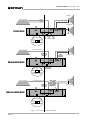
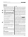
Fig. 2.1 Three System Connection Methods

Power Base Series Power Amplifiers
Page 9
2 Installation
Always remove power from the unit and turn the level
controls off (fully counterclockwise) when making or
breaking connections. This reduces the chance of
blasts that can cause loudspeaker damage.
The guidelines below are provided to help you quickly
get your amplifier installed and ready to go. Be sure to
follow the instructions in Sections 2.1 and 2.2 for the
selected mode of operation. Additional information on
input sensitivity, load protection and required AC
mains is provided in Sections 2.3, 2.4 and 2.5.
1. Install the amplifier in a standard 19 inch (48.3 cm) rack
or place it on a stable surface. The mounting dimensions
are 19 inches (48.3 cm) wide, 3.5 inches (8.9 cm) tall
and 16 inches (40.6 cm) deep behind the mounting sur-
face. IMPORTANT! Allow for adequate ventilation.
2.1 Stereo
1. Turn down the level controls (fully counterclockwise) and
turn off the amplifier.
2. Set the back panel stereo/mono switch to Stereo.
3. If present, remove the Parallel-Mono jumper.
4. Connect the input and output cables as shown in the first
example in Figure 2.1.
5. Turn on the amplifier and adjust the level for each chan-
nel using the back panel level controls.
CAUTION: Never parallel the two outputs by di-
rectly tying them together, and never parallel them
with the output of another amplifier.
2.2 Mono
Your amplifier’s mono modes provide double the
power of Stereo mode in a single channel. In Bridge-
Mono mode, the outputs are wired in series for twice
the output voltage. In Parallel-Mono mode, the outputs
are paralleled for twice the current capacity.
Bridge-Mono mode is provided for loads with an im-
pedance greater than 4 ohms. Parallel-Mono mode
should be used with loads of 4 ohms or less.
B R I D G E - M O N O
1. Turn down the level controls (fully counterclockwise) and
turn off the amplifier.
2. Set the back panel stereo/mono switch to Bridge-Mono.
3. If present, remove the Parallel-Mono jumper.
4. Connect the input and output cables as shown in the sec-
ond example in Figure 2.1. Only use the channel 1 input.
5. Make sure the load is balanced (neither side shorted to
ground) and do not use the black (–) binding posts.
6. Turn on the amplifier and adjust the level. Only use the
channel 1 level control.
P A R A L L E L - M O N O
1. Turn down the level controls (fully counterclockwise) and
turn off the amplifier.
2. Set the back panel stereo/mono switch to Parallel-Mono.
3. Install a solid, 14-gauge (2 mm
2
) or heavier jumper wire
across the two red (+) binding post outputs.
4. Connect the input and output cables as shown in the third
example in Figure 2.1. Only use the channel 1 input.
5. Turn on the amplifier and adjust the level. Only use the
channel 1 level control.
CAUTION: With Parallel-Mono wiring, do not switch
to Stereo or Bridge-Mono mode until the output
jumper wire is removed.
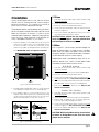
AIR
FLOW
AIR FLOW
AMPLIFIER
(TOP VIEW)
RACK
CABINET
16 in
40.6 cm
2 in
MIN.
17 in
43.2 cm
AIR
FLOW
IMPORTANT: Be sure the back of
the amplifier is supported.
–
+
3
1
2
GND
FROM
PREAMPLIFIER
INPUT
BALANCED
+
–
SHIELD
FROM
PREAMPLIFIER
INPUT
UNBALANCED
+
SHIELD
+
3
1
2
SHIELD
Fig. 2.3 Power Base Input Wiring
2. Use high-quality loudspeaker cables to connect the load
to the amplifier’s outputs. Do not use shielded cable.
3. Use shielded cables to connect audio sources to the
amplifier inputs. Either balanced or unbalanced wiring
can be used as shown below. (XLR connectors are avail-
able with the MT-XLR accessory. See Section 5.)
Fig. 2.2 Do NOT Block Air Flow

Power Base Series Power Amplifiers
Page 10
2.3 Input Sensitivity Adjustment
The input sensitivity switch inside the amplifier is set to
0.775 volts at the factory. It can be changed to 1.4 volts
or a voltage gain of 26 dB as follows:
1. Turn off and unplug the amplifier from the AC source.
2. Remove the access cover on the back panel.
3. Locate the labeled access hole for the sensitivity switch.
4. Set the switch to the desired position.
5. Replace the access cover plate.
When set to 26 dB gain, the
Power Base-1
®
requires a
2.0 volt input, the
Power Base-2
®
requires a 2.5 volt in-
put and the
Power Base-3
™
requires a 3.2 volt input to
deliver full output into an 8 ohm load.
0.77 V
26 dB
SENSITIVITY SWITCH INSIDE ACCESS HOLE
1.4 V
THIS AMPLIFIER IS EQUIPPED WITH SELECTABLE INPUT SENSITIVITY. REMOVE COVER PLATE (ABOVE) TO ACCESS SENSITIVITY SWITCH.
CH-2
INPUT GROUND LIFT
(AFFECTS PHONE INPUTS ONLY.)
(MONO)
INPUT
GAIN
CH-1
INPUT
GAIN
LIFT
BALANCED
INPUT WIRING
+
–
TIP
RING
SLEEVE
GND
UNBALANCED
INPUT WIRING
+
TIP
SLEEVE
GND
0
1
2
3
4
5
6
7
8
9
10
11
12
0
1
2
3
4
5
6
7
8
9
10
11
12
Fig. 2.4 Input Sensitivity Switch
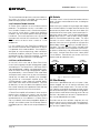
2.4 Additional Load Protection
To protect against excessive power, a fuse can be
added in series with each loudspeaker cable. A single
fuse can protect the entire system, or one can be used
for each driver. High-frequency drivers (tweeters) are
usually more sensitive to large voltage peaks, while
low-frequency drivers (woofers) are typically most sen-
sitive to the heat from average (RMS) output power. To
protect your tweeters, we recommend that you use a
high-speed instrument fuse like the Littlefuse 361000
series. To protect your woofers, we recommend using a
slow-blow fuse that more closely represents the thermal
response of your woofer. Use Figure 2.5 to find the cor-
rect value for either type of fuse.
Example: (A) Find the peak music power of your loudspeaker
(such as 75 watts). (B) Find the loudspeaker impedance (8
ohms). (C) Draw a line between points A and B. The line inter-
sects the middle scale at the correct fuse value (1.5 amps).
1.0
1.2
1.4
1.6
2.5
3
4
5
6
7
8
9
10
12
14
16
20
25
30
20
15
10
8
6
5
4
3
2
1.5
1
.8
.6
.5
.4
.3
.2
.15
.1
.08
3000
2000
1500
1000
800
600
400
300
200
150
100
80
60
40
30
20
15
10
8
6
4
3
2
1.5
1
LOUDSPEAKER IMPEDANCE
(ohms)
FUSE
(amps)
LOUDSPEAKER RATING
PEAK MUSIC POWER
(watts)
(Typically 4 times the continuous average power)
Answer: Fuse = 1.5 A
2
40
Example:
Impedance = 8 ohms.
Peak Power = 75 W
Fig. 2.5 Loudspeaker Fuse Nomograph
2.5 Required AC Mains
All
Power Base
amplifiers are shipped with an appro-
priate line cord and plug. When possible, use a power
receptacle on a dedicated circuit, and always make
sure it will provide the right voltage and sufficient cur-
rent. We do not recommend operating your amplifier
with voltages greater than 10% above or below the
unit’s rated voltage. For example, if your amplifier is
rated for 120 VAC, the line voltage should not exceed
132 VAC.

Power Base Series Power Amplifiers
Page 11
3.3.1
ODEP
Crown invented
ODEP
to keep the amplifier working
under demanding conditions and to increase output
efficiency. To do this, Crown established a rigorous pro-
gram to measure each transistor’s
safe operating area
(SOA). Intelligent circuitry was then designed to simu-
late the instantaneous conditions of the output transis-
tors. Its name describes what it does: Output Device
Emulation Protection, or
ODEP
. In simple terms,
ODEP
compares transistor conditions to their known SOA. If
more power will be asked of them than they can deliver
under the existing conditions,
ODEP
limits the drive
until conditions fall within the SOA. Limiting is propor-
tional and kept to an absolute minimum—only what is
required to prevent output transistor damage. Under
normal conditions, no limiting is required and
ODEP
is
transparent to the audio signal.
ODEP
makes possible a quantum leap in output effi-
ciency and reliability—with
ODEP
, the show goes on.
3.3.2 Ultrasonic and Radio Frequency Protection
An amplifier’s slew rate only needs to be large enough
to deliver the maximum voltage at the highest required
frequency. Higher slew rates actually allow undesirable
ultrasonic and radio frequencies to be reproduced. By
design,
Power Base
amplifiers have a controlled slew
rate to limit the highest frequencies that they reproduce.
Limiting occurs well above 20 kHz so there is no au-
dible effect on performance. This approach protects
the amplifier from radio frequencies and can even pro-
tect some sensitive loads (including some tweeters).
3.3.3 Drive Protection
The drive protection system temporarily removes output
drive to protect the amplifier and its loads. Drive protec-
tion can be activated in two situations. First, if dangerous
subsonic frequencies or direct current (DC) is detected
in the amplifier’s output, the unit will activate its DC/low-
frequency protection circuitry which puts the amplifier in
drive protection mode. This protects the loads and pre-
vents oscillations. The unit resumes normal operation as
soon as the amplifier no longer detects dangerous out-
put. Although it is extremely unlikely that you will ever
activate the amplifier’s DC/low frequency protection
system, improper source materials like subsonic square
waves or input overloads that excessively clip the input
signal can activate this system.
The amplifier’s fault protection system will put the am-
plifier in drive protection mode in rare situations where
heavy common-mode current is detected in the output.
3 Operation
3.1 Precautions
Although your amplifier is protected from external faults,
the following safety precautions are recommended:
1. There are important differences among the Stereo,
Bridge-Mono and Parallel-Mono operating modes.
Please refer to Sections 2 for additional information.
2. WARNING: Do not change the position of the
stereo/mono switch unless the amplifier is first
turned off.
3. CAUTION: In Parallel-Mono mode, a jumper is
used to connect the red binding post outputs.
Be sure to remove this jumper for Bridge-Mono
or Stereo mode, or high distortion and excessive
heating will occur. Also, make sure the stereo/
mono switch is set to the proper position.
4. Use care when making connections, selecting sig-
nal sources and controlling the output level. The
load you save may be your own!
5. Do not short the ground lead of an output cable to
the input signal ground. This will form a ground loop
and may cause oscillations.
6. Operate the amplifier from AC mains of not more
than 10% variation above or below the selected line
voltage and only at the specified line frequency.
7. Never connect the output to a power supply out-
put, battery or power main. Such connections
may result in electrical shock.
8. Tampering with the circuitry by unqualified person-
nel or making unauthorized circuit changes may be
hazardous and invalidates all agency listings.
Remember: Crown is not liable for any damage that re-
sults from overdriving other system components.
3.2 Power Indicator
When lit, the amber power indicator (to the left of the
power switch) shows that the amplifier has been turned
on. It is driven only by the low-voltage power supply
and does not indicate the status of the high-voltage
supplies.
3.3 Protection Systems
Power Base
amplifiers have extensive protection sys-
tems, including
ODEP
, ultrasonic/RF protection, drive
protection, transformer thermal protection and fuses or
circuit breakers that protect the power supplies.

Power Base Series Power Amplifiers
Page 12
The unit should never output heavy common-mode cur-
rent unless its circuitry is damaged. Activating drive
protection helps prevent further damage.
3.3.4 Transformer Thermal Protection
All
Power Base
amplifiers have transformer thermal
protection. This protection circuitry is activated in un-
usual situations where the unit’s transformer tempera-
ture rises to unsafe levels. Under these abnormal
conditions, the unit removes power to the high-voltage
transformer. The fan will continue to run in all units ex-
cept those with 220/240 VAC transformers. The ampli-
fier will return to normal after it cools to a safe
temperature.
It is very unlikely that your
Power Base
amplifier will
ever activate transformer thermal protection as long as
it is operated within rated conditions. Your amplifier is
designed to continue operating under conditions
where other amplifiers would fail. But even when you
exceed the limits of a
Power Base
amplifier, it still pro-
tects itself—and your investment—from damage.
3.3.5 Fuses and Circuit Breakers
All 120 VAC, 60 Hz units and all
Power Base-3
units
have a fuse that protects the low-voltage power supply
and cooling fan. The
Power Base-1
and
Power Base-2
high-voltage power supplies are protected by fuses,
while the
Power Base-3
high-voltage power supplies
are protected by a circuit breaker. With rated loads
and output levels, these fuses (or the circuit breaker)
should only shut down the amplifier in the incredibly
rare instance of a catastrophic amplifier failure. The
ODEP
protection system keeps the amplifier opera-
tional under most other severe conditions. The fuses
(or breaker) can also shut down the amplifier in situa-
tions where extremely low-impedance loads and high
output levels result in excessive current draw.
A
Power Base
amplifier will not blow its fuses or trip its
breaker unless something is wrong. In the rare event
that an internal fuse blows, please refer the unit to a
qualified technician. If the breaker in a
Power Base-3
trips, try to identify and correct the problem before re-
setting it with the back panel Circuit Breaker Reset. If
the problem persists, refer the unit to a qualified techni-
cian.
3.4 Controls
The Power switch is th only control located on the front
panel. All others are located on the rear, including the
level controls.
When making any setup or wiring changes, don’t forget
to turn off the amplifier, turn down the level controls and
disconnect the power cord. Be sure to turn down (full
counterclockwise) the channel 2 level control when us-
ing either mono mode. The Parallell Mono/Stereo/
Bridge Mono switch is used to select Stereo, Bridge-
Mono or Parallel-Mono operating modes. The Input
Ground Lift switch isolates the phone jack input
grounds from the chassis ground to help prevent
ground loops. It does not affect any installed input ac-
cessories. The Input Sensitivity Switch, located inside
the back cover plate, sets the amplifier’s input sensitiv-
ity (refer to subsection 2.3 for information on changing
this switch). And the
Power Base-3
has a back panel
Circuit Breaker Reset button that resets the circuit
breaker (refer to subsection 3.3.5).
CH-2
INPUT GROUND LIFT
(AFFECTS PHONE INPUTS ONLY.)
(MONO)
INPUT
GAIN
CH-1
INPUT
GAIN
LIFT
0
1
2
3
4
5
6
7
8
9
10
11
12
0
1
2
3
4
5
6
7
8
9
10
11
12
CHANNEL 2
LEVEL CONTROL
CHANNEL 1
LEVEL CONTROL
3.5 Filter Cleaning
A dust filter is provided on the unit’s air intake. If it be-
comes clogged, the unit will cool less efficiently and
may produce lower output levels. To clean the filter,
use a phillips screwdriver to remove the three screws
the secure the front grille. Use mild dishwashing deter-
gent and warm water for best cleaning results. Be sure
the filter is dry before you reinstall it. Replacement fil-
ters may be ordered from the factory.
Dust filters are not 100% efficient—long term this may
require internal heat-sink cleaning by a qualified tech-
nician. Internal cleaning information is available from
our Technical Support Group.
Fig. 3.1 Back Panel Level Controls

Power Base Series Power Amplifiers
Page 13
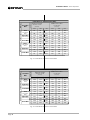
4 Specifications
All specifications apply to units in Stereo mode with 8-ohm loads
and an input sensitivity of 26 dB unless otherwise specified.
Standard 1 kHz Power: refers to maximum average power in
watts at 1 kHz with 0.1% THD+noise.
Full Bandwidth Power: refers to maximum average power in
watts from 20 Hz to 20 kHz with 0.1% THD+noise.
120 VAC, 60 Hz Units: refers to amplifiers with dedicated trans-
formers for 120 VAC, 60 Hz power mains.
Performance
Frequency Response: ±0.1 dB from 20 Hz to 20 kHz
at 1 watt.
Phase Response: ±10 degrees from 10 Hz to 20 kHz
at 1 watt.
Signal-to-Noise: A-weighted, better than 105 dB be-
low full bandwidth power. Better than 100 dB below full
bandwidth power from 20 Hz to 20 kHz.
Total Harmonic Distortion (THD): Less than 0.05%
at full bandwidth power from 20 Hz to 1 kHz increas-
ing linearly to 0.1% at 20 kHz.
Intermodulation Distortion (IMD): (60 Hz and 7 kHz
4:1) Less than 0.05% from less than 158 milliwatts to full
bandwidth power.
Damping Factor: Greater than 1,000 from 10 Hz to 400 Hz.
Crosstalk
Power Base-1
: Greater than 75 dB below full band-
width power from 50 Hz to 2 kHz, rising linearly to
greater than 60 dB at 20 kHz.
Power Base-2
: Greater than 90 dB below full band-
width power from 50 Hz to 2 kHz, rising linearly to
greater than 66 dB at 20 kHz.
Power Base-3
: Greater than 90 dB below full band-
width power from 50 Hz to 4 kHz, rising linearly to
greater than 70 dB at 20 kHz.
Common Mode Rejection (CMR): Better than 70 dB
below rated full bandwidth power from 20 Hz to 1 kHz
falling linearly to better than 50 dB at 20 kHz.
Controlled Slew Rate: Greater than 13 volts/ms.
Voltage Gain: 20:1 ±3% or 26 dB ±0.25 dB at the maxi-
mum level setting (Input Sensitivity switch set to its 26
dB position).
Power Base-1
: 51:1 ±12% or 34.3 dB ±1 dB at 0.775
volt sensitivity; 28:1 ±12% or 29.1 dB ±1 dB at 1.4 volt
sensitivity.
Power Base-2
: 64:1 ±12% or 36.2 dB ±1 dB at 0.775
volt sensitivity; 35:1 ±12% or 31.0 dB ±1 dB at 1.4 volt
sensitivity.
Power Base-3
: 83:1 ±12% or 38.4 dB ±1 dB at 0.775
volt sensitivity; 46:1 ±12% or 33.3 dB ±1 dB at 1.4 volt
sensitivity.
Power
Output Power:
The following specifications are guaran-
teed minimums for standard 1 kHz power. For more infor-
mation, see the power matrices in Figures 4.1 through 4.6
(maximum average power @ 0.1% THD + N).
Power Base-1
Stereo mode (both channels driven):
240 watts into 4 ohms.
200 watts into 8 ohms.
Bridge-Mono mode:
455 watts into 8 ohms.
395 watts into 16 ohms.
Parallel-Mono mode:
455 watts into 2 ohms.
400 watts into 4 ohms.
Power Base-2
Stereo mode (both channels driven):
460 watts into 4 ohms.
325 watts into 8 ohms.
Bridge-Mono mode:
910 watts into 8 ohms.
660 watts into 16 ohms.
Parallel-Mono mode:
920 watts into 2 ohms.
655 watts into 4 ohms.
Power Base-3
Stereo mode (both channels driven):
760 watts into 4 ohms.
540 watts into 8 ohms.
Bridge-Mono mode:
1525 watts into 8 ohms.
1090 watts into 16 ohms.
Parallel-Mono mode:
1530 watts into 2 ohms.
1080 watts into 4 ohms.
Load Impedance: Safe with all types of loads. Rated
for 4 to 8 ohms in Stereo, 8 to 16 ohms in Bridge-
Mono and 2 to 4 ohms in Parallel-Mono mode.

Power Base Series Power Amplifiers
Page 14
Required AC Mains: Current, frequency and voltage
requirements are provided on each unit’s back panel.
All models draw 90 watts or less at idle.
Power Base-1
: Draws up to 6 amps of current.
Power Base-2
: Draws up to 10 amps of current.
Power Base-3
: Draws up to 15 amps of current.
Low-Voltage Power Supply: A ±24 VDC fanformer
supply (fan motor winding) regulated to ±15 VDC.
AC Connector: An appropriate AC line cord and plug
are provided. 120 VAC, 60 Hz units have a standard
3-wire, 15-amp grounded connector (NEMA 5-15P).
Controls
Power: A front panel rocker switch used to turn the
amplifier on and off.
Level: A back panel rotary potentiometer for each chan-
nel used to control the output level.
Stereo/Mono: A three-position back panel switch used
to select Stereo, Bridge-Mono or Parallel-Mono mode.
Sensitivity: A three-position switch inside the back
cover plate used to select the input sensitivity for both
channels: 0.775 volts or 1.4 volts for standard 1 kHz
power, or 26 dB voltage gain (see Section 2.3).
Input Ground Lift: A two-position back panel switch
used to isolate the phone jack and chassis grounds.
Reset (
Power Base-3
only): A back panel push but-
ton used to reset the circuit breaker that protects the
power supplies.
Indicators
Power: This amber indicator shows the on/off status of
the low voltage power supply.
Input/Output
Input Connector: Balanced ¼ inch phone jacks. See
Section 5 for XLR and barrier block accessories.
Input Impedance: Nominally 20 K ohms, balanced;
10 K ohms, unbalanced.
Output Connector: Two sets of color-coded 5-way bbinding
posts (for banana plugs, spade lugs or bare wire).
Output Impedance: Less than 10 milliohms in series
with less than 2 microhenries.
DC Output Offset: Less than 10 millivolts.
Output Signal
Stereo: Unbalanced, two-channel.
Bridge-Mono: Balanced, single-channel. Channel 1
controls are active; Channel 2 controls should be
turned down and not used.
Parallel-Mono: Unbalanced, single-channel. Channel
1 controls are active; Channel 2 controls should be
turned down and not used.
Protection
Power Base
amplifiers are protected against shorted,
open or mismatched loads; overloaded power supplies;
excessive temperature, chain destruction phenomena,
input overload and high-frequency blowups. They also
protect loudspeakers from input and output DC, as well
as providing protection from turn-on/turn-off transients.
If operating conditions are unreasonable, the patented
ODEP
circuitry proportionally limits the drive level to pro-
tect the output transistors, particularly in the case of el-
evated temperature. A thermal switch imbedded in the
transformer protects the power supplies from overload.
In the rare event that a transformer overheats, the ther-
mal switch removes power, waits until the unit has cooled
to a safe temperature and then resets itself.
Turn On: Four second delay with no dangerous tran-
sients. Contact us if you need to change the delay.
Construction
Durable black finish on steel chassis with special “flow-
through” ventilation from front to side panels.
Cooling: Internal heat sinks with forced-air cooling
for rapid, uniform heat dissipation.
Dimensions: Standard 19-inch (48.3 cm) rack mount
width (EIA RS-310-B), 3.5-inch (8.9 cm) height and
16-inch (40.6 cm) depth behind the mounting surface.
Approximate Weight: Center of gravity is 6 inches
(15.2 cm) behind front mounting surface.
120 VAC, 60 Hz Units:
Power Base-1
: 30 pounds (13.6 kg) net; 34 pounds
(15.4 kg) shipping weight.
Power Base-2
: 34 pounds (15.4 kg) net; 38 pounds
(17.2 kg) shipping weight.
Power Base-3
: 36 pounds (16.3 kg) net; 40 pounds
(18.2 kg) shipping weight.

Power Base Series Power Amplifiers
Page 15
8
Power Base-1 – Minimum Guaranteed Power (Watts)
Stereo-Mono
Mode
Stereo
(both channels
driven)
Bridge-Mono
(balanced output)
Parallel-Mono
16
4
0.1% THD + Noise
(See note 4)
1 kHz 20Hz-20kHz
180
350
175
350
200
390
390
200
390
390
Maximum Average
Load (Ohms)
AC Mains120 VAC, 60 Hz Units
1 kHz
0.1% THD+N
(See note 1)
0.1% THD+N
(See note 2)
240
200
455
395
455
400
230
205
465
410
440
410
20Hz-20kHz
175
185
360
370
165
185
355
375
4
2
8
0.05% THD+N
(See note 3)
1 kHz
8
Stereo
(both channels
driven)
Bridge-Mono
(balanced output)
Parallel-Mono
16
International Units
4
2
8
235
200
455
390
445
395
225
200
455
405
430
405
4
FTC Continuous Average
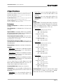
Fig. 4.1 Power Base-1 Minimum Power Matrix
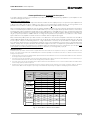
Crown specifications are guaranteed for three years.
In an effort to provide you with as much information as possible about the high power-producing capabilities of your amplifier, we have
created the following power matrices.
Minimum Power Specifications
Crown’s minimum power specifications represent the absolute smallest amount of output power you can expect from your amplifier when it
is driven to full output under the given conditions. Some spaces in each matrix may be left blank because the same guarantee is not
provided for those conditions—however, your amplifier will perform well under all conditions listed in each matrix.
When measuring power, 0.1% THD appears to be the industry standard for distortion. Two of the maximum average power specifications
shown in each minimum power matrix are measured at 0.1% THD so you can easily compare Crown specifications to those of other manu-
facturers. But this high level of distortion actually allows for some clipping which is undesirable. Because of this, a maximum average power
spec at 0.05% THD is included in each minimum power matrix which represents non-clipped conditions. Although most manufacturers do
not give you power specifications at 0.05% THD, we encourage them to provide these specifications so you will have a more realistic
representation of the way amplifiers should be used in the real world—without a clipped output signal.
Many manufacturers publish power specs with a tolerance of ±1 dB or worse. This means their amplifier can deviate more than 20% in
output! A 100 watt amplifier would meet their specification if it only produced 79.4 watts. Other manufacturers qualify their specs by saying
they are “typical,” “subject to manufacturing tolerances,” “single channel driven” or that they are specified with “fuses bypassed.” Each of
these statements effectively removes any performance guarantee. In fact, some manufacturers use these tactics to generate large power
numbers, and they don’t even print a disclaimer. We take a different approach at Crown—our amplifiers are
guaranteed
to meet or exceed
their specifications for three years. Further, because our published specs are set below our “in-house” measurements, you can expect
every
Crown amplifier to
exceed
its published minimum power specs. We believe you should get what you pay for.
Minimum Power Notes:
All minimum power specifications are based on 0.1% regulated AC mains and an ambient room temperature of 70° F (21° C). A 100V, 50Hz model was used
because of its higher current demand. The standard EIA power measurement (RS-490) is not identified here because it is identical to the FTC Continuous
Average Power specification.
1. A 1 kHz sine wave is presented to the amplifier and the output monitored for nonlinear distortion. The level is increased until the THD reaches 0.1%. At this level
the average power per channel is reported.
2. A sine wave is presented to the amplifier over the range from 20 Hz to 20 kHz and the output monitored for nonlinear distortion. The level at each frequency is
increased until the THD reaches 0.1%. At this level the average power per channel is reported.
3. A 1 kHz sine wave is presented to the amplifier and the output monitored for nonlinear distortion. The level is increased until the THD reaches 0.05%. At this
level the average power per channel is reported.
4. Continuous power in the context of Federal Trade Commission testing is understood to be a minimum of five minutes of operation. Harmonic distortion is
measured as the RMS sum total and given as a percentage of the fundamental output voltage. This applies for all wattages greater than 0.25 watts.

Power Base Series Power Amplifiers
Page 16
8
Power Base-2 –
Minimum Guaranteed Power (Watts)
Stereo-Mono
Mode
Stereo
(both channels
driven)
Bridge-Mono
(balanced output)
Parallel-Mono
16
4
FTC Continuous Average
0.1% THD + Noise
(See note 4)
1 kHz 20Hz-20kHz
265
530
325
275
640
545
385
310
815
625
805
630
395
305
790
615
785
610
Maximum Average
Load (Ohms)
AC Mains120 VAC, 60 Hz Units
1 kHz
0.1% THD+N
(See note 1)
0.1% THD+N
(See note 2)
460
325
910
660
920
655
425
310
855
620
850
620
20Hz-20kHz
425
310
830
615
390
290
775
575
4
2
8
0.05% THD+N
(See note 3)
1 kHz
460
325
905
655
915
650
425
305
850
615
845
615
8
Stereo
(both channels
driven)
Bridge-Mono
(balanced output)
Parallel-Mono
16
International Units
4
2
8
4
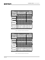
Fig. 4.2 Power Base-2 Minimum Power Matrix
8
Power Base-3 –
Minimum Guaranteed Power (Watts)
Stereo-Mono
Mode
Stereo
(both channels
driven)
Bridge-Mono
(balanced output)
Parallel-Mono
16
4
FTC Continuous Average
0.1% THD + Noise
(See note 4)
1 kHz 20Hz-20kHz
495
985
485
470
1085
930
530
1055
1065
555
510
1115
1025
1115
1030
Maximum Average
Load (Ohms)
AC Mains120 VAC, 60 Hz Units
1 kHz
0.1% THD+N
(See note 1)
0.1% THD+N
(See note 2)
760
540
1525
1090
1530
1080
680
510
1335
1025
1365
1015
20Hz-20kHz
715
525
1430
1045
630
495
1240
980
4
2
8
0.05% THD+N
(See note 3)
1 kHz
755
540
1500
1075
1520
1080
660
505
1305
1000
1340
1010
8
Stereo
(both channels
driven)
Bridge-Mono
(balanced output)
Parallel-Mono
16
International Units
4
2
8
4
Fig. 4.3 Power Base-3 Minimum Power Matrix

Power Base Series Power Amplifiers
Page 17
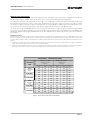
Maximum Power Specifications
Crown’s maximum power specifications represent the largest amount of output power you can expect from your amplifier when it is driven to
full output under the given conditions. These specifications can be used to prevent loudspeaker and hearing damage.
The maximum power matrices include specifications for single cycle and 40 millisecond burst sine waves. Burst signals act like large
transient peaks that are present in common source signals. Loudspeakers can respond to a single cycle burst, so the single cycle burst
specifications should be used to help you protect your loudspeakers. In contrast, a 40 millisecond burst represents the typical response time
of the human ear. Your ear will not respond to the entire dynamic change of a burst that lasts less than 40 milliseconds.
The specifications are provided at 0.05% THD because this represents a low distortion condition. To help you operate your amplifier within
these tolerances, Crown’s premium amplifiers include an input/output comparator that shows when the amplifier has exceeded 0.05% THD.
Operating the amplifier at levels higher than 0.05% THD can result in output power levels that are higher than those listed in the maximum
power matrices.
Maximum Power Notes:
All maximum power specifications are based on 0.1% regulated AC mains and an ambient room temperature of 70° F (21° C). A 100V, 50Hz model was used
because of its higher current demand. Although it is an unusual condition, your amplifier can function well with AC mains voltages up to 10% over the specified
line voltage. With overvoltage conditions, your amplifier may be capable of delivering instantaneous power levels up to 20% greater than the specifications in the
matrix.
1. A single cycle sine wave is presented to the amplifier and monitored for nonlinear distortion. The average power during the burst is reported. Loudspeakers
must be able to withstand this level if they are to be safely used with this amplifier.
2. A 40 millisecond sine wave burst (10 percent duty cycle) is presented to the amplifier and monitored for nonlinear distortion. The average power during the
burst is reported. This power level is a measurement of the amplifier’s maximum transient power that can be perceived by the human ear.
8
Power Base-1 – Maximum Power (Watts)
Stereo-Mono
Mode
Stereo
(both channels
driven)
Bridge-Mono
(balanced output)
Parallel-Mono
16
4
40 Millisecond Tone Burst
0.05% THD + Noise
(See note 2)
7 kHz 50 Hz
315
230
600
470
620
465
320
260
635
520
615
515
335
300
620
610
640
600
330
335
670
670
625
670
Single Cycle Tone Burst
Load (Ohms)
AC Mains120 VAC, 60 Hz Units
At less than 0.05% THD
(See note 1)
50 Hz
325
265
630
540
635
530
325
290
640
580
620
580
4
2
8
1 kHz
335
310
640
630
645
615
330
345
650
690
625
690
8
Stereo
(both channels
driven)
Bridge-Mono
(balanced output)
Parallel-Mono
16
International Units
4
2
8
4
1 kHz 7 kHz
295
220
565
440
580
430
315
235
625
470
615
475
310
230
580
455
605
450
330
250
655
495
625
490
Fig. 4.4 Power Base-1 Maximum Power Matrix

Power Base Series Power Amplifiers
Page 18
8
Power Base-2 –
Maximum Power (Watts)
Stereo-Mono
Mode
Stereo
(both channels
driven)
Bridge-Mono
(balanced output)
Parallel-Mono
16
4
40 Millisecond Tone Burst
0.05% THD + Noise
(See note 2)
7 kHz 50 Hz
550
400
1190
795
1185
805
605
410
1200
820
1185
820
790
515
1805
1020
1645
1020
885
510
1785
1020
1655
1015
Single Cycle Tone Burst
Load (Ohms)
AC Mains120 VAC, 60 Hz Units
At less than 0.05% THD
(See note 1)
50 Hz
655
460
1410
915
1440
915
720
465
1440
920
1390
915
4
2
8
1 kHz
805
525
1850
1060
1685
1055
900
530
1770
1055
1670
1055
8
Stereo
(both channels
driven)
Bridge-Mono
(balanced output)
Parallel-Mono
16
International Units
4
2
8
4
1 kHz 7 kHz
500
375
1090
755
1085
750
545
380
1075
750
1065
750
520
395
1125
780
1120
775
565
395
1120
785
1110
775
Fig. 4.5 Power Base-2 Maximum Power Matrix
Fig. 4.6 Power Base-3 Maximum Power Matrix
8
Power Base-3 –
Maximum Power (Watts)
Stereo-Mono
Mode
Stereo
(both channels
driven)
Bridge-Mono
(balanced output)
Parallel-Mono
16
4
40 Millisecond Tone Burst
0.05% THD + Noise
(See note 2)
7 kHz 50 Hz
910
610
1780
1250
1790
1225
970
675
1945
1360
1940
1360
1525
838
3040
1675
3015
1665
1695
920
3380
1840
3345
1825
Single Cycle Tone Burst
Load (Ohms)
AC Mains120 VAC, 60 Hz Units
At less than 0.05% THD
(See note 1)
50 Hz
1090
715
2155
1415
2140
1420
1190
785
2355
1540
2330
1570
4
2
8
1 kHz
1575
870
3140
1740
3135
1735
1750
960
3490
1915
3485
1895
8
Stereo
(both channels
driven)
Bridge-Mono
(balanced output)
Parallel-Mono
16
International Units
4
2
8
4
1 kHz 7 kHz
815
570
1615
1135
1605
1135
870
625
1725
1235
1720
1235
855
595
1690
1180
1680
1170
920
645
1805
1285
1800
1270

Power Base Series Power Amplifiers
Page 19
5 Accessories
There are two accessories available at the time of this
printing: the
MT-XLR
and the
MT-BB
. Important: The
MT-XLR
and
MT-BB
must be installed at a Crown
Factory Service Center or the Crown factory.
5.1 MT-XLR
The
MT-XLR
is an accessory panel that provides two
standard 3-pin female XLR input connectors. The
MT-XLR
accessory makes it easy to quickly change
connections in a system that uses standard XLR con-
nectors. It can also be used in systems that need to
daisy chain an input signal from one amplifier to an-
other. Because the
MT-XLR
connectors are wired in
parallel with the amplifier’s built in phone jack connec-
tors, an input signal fed to either input can be fed to
another amplifier from the unused connector for that
channel.
5.2 MT-BB
The
MT-BB
is an accessory panel that provides barrier
strip input connectors. An
MT-BB
accessory might be
desirable in applications requiring bare wire connec-
tions. It can also be used to daisy chain an input signal
from one amplifier to another just like the
MT-XLR
.
Fig. 5.1 The MT-XLR
MT
-
BB
– +– +
CH-2 INPUT CH-1 INPUT
Fig. 5.2 The MT-BB
MT
-
XLR
CH-2 INPUT CH-1 INPUT
PUSHPUSH
3
12
GND
THESE XLR INPUTS ARE CONNECTED IN PARALLEL WITH THE PHONE JACK INPUTS.

Power Base Series Power Amplifiers
Page 20
6 Service
This unit has very sophisticated circuitry which should
only be serviced by a fully trained technician. This is
one reason why each unit bears the following label:
CAUTION: To prevent electric shock, do not re-
move covers. No user serviceable parts inside. Re-
fer servicing to a qualified technician.
6.1 Worldwide Service
Service may be obtained from an authorized service
center. (Contact your local Crown/Amcron representa-
tive or our office for a list of authorized service centers.)
To obtain service, simply present the bill of sale as
proof of purchase along with the defective unit to an
authorized service center. They will handle the neces-
sary paperwork and repair.
Remember to transport your unit in the original factory
pack. We will pay the surface shipping costs both
ways for warranty service to the authorized service
center nearest you after receiving copies of all ship-
ping receipts. You must bear the expense of all taxes,
duties, and customs fees when transporting the unit.
6.2 North American Service
Service may be obtained in one of two ways: from an
authorized service center or from the factory. You may
choose either. It is important that you have your copy of
the bill of sale as your proof of purchase.
6.2.1 Service at a North American Service Center
This method usually saves the most time and effort.
Simply present your bill of sale along with the defective
unit to an authorized service center to obtain service.
They will handle the necessary paperwork and repair.
Remember to transport the unit in the original factory
pack. A list of authorized service centers in your area
can be obtained from our Technical Support Group.
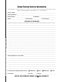
6.2.2 Factory Service
To obtain factory service, fill out the service informa-
tion page that follows and send it along with your proof
of purchase and the defective unit to the Crown factory.
For warranty service, we will pay for ground shipping
both ways in the United States after receiving copies of
the shipping receipts. Shipments should be sent “UPS
ground.” (If the unit is under warranty, you may send it
C.O.D. for the cost of freight via UPS ground.) The fac-
1. When sending a Crown product to the factory for
service, be sure to fill out the service information
form that follows and enclose it inside your unit’s
shipping pack. Do not send the service informa-
tion form separately.
2. To ensure the safe transportation of your unit to
the factory, ship it in an original factory packing
container. If you don’t have one, call or write
Crown’s Parts Department. With the exception of
polyurethane or wooden crates, any other pack-
ing material will not be sufficient to withstand the
stress of shipping. Do not use loose, small size
packing materials.
3. Do not ship the unit in any kind of cabinet (wood
or metal). Ignoring this warning may result in ex-
tensive damage to the unit and the cabinet. Ac-
cessories are not needed—do not send the
instruction manual, cables and other hardware.
If you have any questions, please call or write the
Crown Technical Support Group.
Always use the
original factory pack
to transport the unit.
tory will return it via UPS ground. Please contact us if
other arrangements are required.
Factory Service Shipping Instructions:
Crown Audio Division
Technical Support / Factory Service
Plant 2 SW, 1718 W. Mishawaka Rd., Elkhart,
Indiana 46517 U.S.A.
Telephone:
219-294-8200
800-342-6939 (North America,
Puerto Rico, and Virgin Islands only)
Facsimile:
219-294-8301 (Technical Support)
219-294-8124 (Factory Service)
Fax Back:
219-293-9200
800-294-4094 (North America only)
Internet:
http://www.crownintl.com
Page is loading ...
-
 1
1
-
 2
2
-
 3
3
-
 4
4
-
 5
5
-
 6
6
-
 7
7
-
 8
8
-
 9
9
-
 10
10
-
 11
11
-
 12
12
-
 13
13
-
 14
14
-
 15
15
-
 16
16
-
 17
17
-
 18
18
-
 19
19
-
 20
20
-
 21
21


Ask a question and I''ll find the answer in the document
Finding information in a document is now easier with AI
Related papers
-
Crown CSL Series User manual
-
-
Crown Macro-Tech MA-5002VZ User manual
-
Crown Audio MA-5002VZ User manual
-
-
 Crown Audio POWER-TECH 3 User manual
-
-
-
-
Crown Com-Tech CT-210 User manual

Other documents
-
 Crown Audio MA-3600VZ User manual
-
 Crown Audio Stereo Amplifier 1201, 2401 User manual
-
 Crown Audio Stereo Amplifier 1202 & 2402 User manual
-
 Crown Audio MA-2402 User manual
-
 Crown Audio 133472-1A User manual
-
 Crown Audio CE SERIES User manual
-
 Crown Audio CE SERIES User manual
-
 Crown Audio ce 4000 User manual
-
 Crown Audio XS1200 User manual
-
 Crown Audio PT 2.1 User manual


