Page is loading ...

Installation & Maintenance Data IM 812
Group: PTAC/PTHP
Part Number: TBD
Date: July 2004
McQuay/Remington
Packaged Terminal Air Conditioners and Heat Pumps – B+ Model
®
©2004 McQuay/Remington Air Conditioning
For Parts & Support Call 800-411-7822

IM 812 / Page 2 of 24
General Description ............................................................ 2
Warning ............................................................................... 2
Inspection ........................................................................... 2
Nomenclature...................................................................... 3
Control Features .............................................................. 4-5
Wall Opening Requirements and Unit Dimensions ............. 6
Installation of Optional Condensate Drain Kit ..................... 7
Subbase Installation............................................................ 8
Power Supply and Control Wiring....................................... 8
Wall Sleeve Installation
Thin Wall Construction ................................................. 9
Medium Thick Wall Construction ............................... 10
Table of Contents
The installer must determine and follow all applicable
codes and regulations. This equipment presents hazards
of electricity, rotating parts, sharp edges, heat and weight.
Failure to read and follow these instructions can result in
property damage, severe personal injury or death. This
equipment must be installed by experienced, trained
personnel only.
Thick Wall Construction ............................................. 11
Wall Sleeve Extension and Louver Frame......................... 12
Outdoor Louvers ............................................................... 13
Installation of Louvers and Chassis .................................. 14
Equipment Start-up .......................................................... 15
Remote Mounted Thermostat ........................................... 17
Wiring Diagrams................................................................ 18
Scheduled Maintenance ................................................... 19
Spare Parts ....................................................................... 19
Shipping Weights .............................................................. 20
Refrigeration Cycle ........................................................... 20
Trouble Shooting .......................................................... 21-23
General Description
McQuay
®
/Remington
®
Packaged Terminal Air Conditioners and
Heat Pumps are designed and built for through-the-wall
installation in either new or existing buildings. The self-con-
tained refrigerant system delivers cooling to the desired space.
Heating can be accomplished with electric resistance or with
reverse cycle technology (heat pump models only). Generally,
an estimate for capacity selection is 35 BTUH per square foot
of floor space (cooling) and 4 BTUH (1.25 watts) per cubic
foot (heating). The architect or engineer must verify the selec-
tion. Note that the heat pump reverse cycle generates ap-
proximately 10 BTUs per electrical watt as compared to 3.4
BTUs per watt with resistance electric heat. The unit will re-
start at it’s last setting after a power interruption. A complete
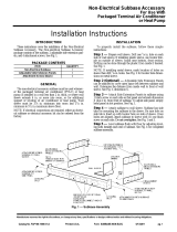
unit consists of the following components, ordered and
shipped separately.
1. Heating/Cooling Chassis and Front Panel.
2. Wall Sleeve.
3. Outdoor Louver.
4. Subbase – Optional for 208V and 230V units but manda-
tory for all 265V.
5. Separate plug-in power cord (selects heater size).
NOTE: PTAC/HP 09 & 012, 208/230 V, 2.9/3.5 Kw heaters
are also available with factory installed power cords.
6. Electrical receptacle – Optional for 208V and 230V units
but mandatory for all 265V.
7. Plug cord cover – Optional for 208V and 230V units but
mandatory for all 265V.
WARNING
!
This product was carefully packed and thoroughly
inspected before leaving the factory. Responsibility
for its safe delivery was assumed by the carrier upon
acceptance of the shipment. Claims for loss or damage
sustained in transit must therefore be made upon the
carrier, as follows:
VISIBLE LOSS OR DAMAGE
Any external evidence of loss or damage must be
noted on the freight bill or carrier’s receipt, and signed
by the carrier’s agent. Failure to adequately describe
such external evidence of loss or damage may result
in the carrier’s refusing to honor a damage claim. The
form required to file such a claim will be supplied by
the carrier.
CONCEALED LOSS OR DAMAGE
Concealed loss or damage means loss or damage
which does not become apparent until the product
has been unpacked. The contents may be damaged in
transit due to rough handling even though the carton
may not show external damages. When the damage is
discovered upon unpacking, make a written request
for inspection by the carrier’s agent within fifteen (15)
days of the delivery date. File a claim with the carrier
since such damage is the carrier’s responsibility.
Inspect unit nameplate to be certain the voltage is the
same as the voltage that will be delivered to the unit. The
receptacle must match the plug on the unit cord. Improper
electrical wiring can cause property damage, severe per-
sonal injury or death.
NOTICE
WARNING
!
Disconnect all electrical power before servicing
unit to prevent injury or death due to electrical
shock.
Hazardous Voltage!
Disconnect all electric power including remote
disconnects before servicing. Failure to disconnect power
before servicing can cause severe personal injury
or death.
Use copper conductors only. Unit terminals are not
designed to accept other types of conductors.
Failure to do so may cause damage to the
equipment.
WARNING
!
CAUTION
!
DANGER
!

IM 812 / Page 3 of 24
Figure 1. Exploded View of Complete Unit (Shown without subbase or power cord)
Louver
Wall Sleeve
Chassis
Front Panel
▲
▲
▲
▲
Product Nomenclature
PTAC : Packaged Terminal Air-Conditioner
PTHP : Packaged Terminal Heat-Pump
07 = 7,000 Btuh Nominal Cooling Capacity
09 = 9,000 Btuh Nominal Cooling Capacity
12 = 12,000 Btuh Nominal Cooling Capacity
15 = 15,000 Btuh Nominal Cooling Capacity
PTAC 07 B 208 KX B A*
B = Vintage B
208 = 208/230v
265 = 265v
B = B Control
C = C Control
KX = 208/230v
MX = 265v
A = Universal Heater
B = Fixed Heater
* Fixed heater is 2.9/3.5 Kw, 208/230V only, with factory installed 20 amp power cord - available on unit size 09 and 012 only.
Universal heater is nominal 2, 3, or 5 Kw (or no heat for cooling only applications), determined by power cord selection. See
Table 2, page 15.
Now that you have made an investment in modern, efficient McQuay
®
/Remington
®
equipment, its care and
operation should be a high priority. For training information on all McQuay HVAC products, please visit us at
www.mcquay.com and click on Training or phone 540-248-0711 and ask for the Training Department.

IM 812 / Page 4 of 24
CAUTION
!
Control Features
Standard Control
Control Pad – Can remain unit-mounted as shipped, or can
be remote wall mounted. Remote mounting requires an
accessory 20´, 35´ or 50´ low-voltage wire harness, control
pad mounting plate and snap-in decorative cover to replace
the control pad at the unit. The mounting location must be
away from cold drafts, discharge air, outside walls, etc., be-
cause the room temperature sensor is mounted in the control
pad (dip switch #2 of 4 on front of control box must be “ON”).
A wireless hand-held remote controller is also available as an
accessory, which allows control of the conditioner from any-
where in the room.
Heat – Select by pressing the ON/OFF key to “ON” and the
MODE key to “HEAT.” Use the
왕
+
or 왓
-
key to set the desired
room temperature (60-85
O
F).
NOTE: Heat pumps will not operate in reverse cycle un-
less temperature setting is within 2
o
F of room tempera-
ture. Otherwise, unit will heat with electric heaters until
satisfied. The next call for heat will be reverse cycle, pro-
vided the outdoor temperature is above the 30-40
o
F range.
When the outdoor temperature is less than 25
o
F, most of
the heating will be with electric resistance. Between 25
o
F
and 40
o
F, the primary heat will be reverse cycle with occa-
sional resistance heat as required to maintain room tem-
perature. Above 40
o
F, all heating will be by reverse cycle.
Cool – Select by pressing the ON/OFF key to “ON” and the
MODE key to “COOL.” Use the
왕
+
or 왓
-
key to set the desired
room temperature (60-85
O
F).
Fan – Select by pressing the ON/OFF key to “ON” and the
MODE key to “FAN”. Press the FAN key to select high or low
speed. In this mode, only the indoor fan will operate and there
will be no heating or cooling.
Cool/Dry – Press the ON/OFF key to “ON” and the MODE key
to “COOL”. Press and hold the MODE key for 15 seconds to
activate “COOL/DRY”. Use the
왕
+
or 왓
-
key to set the desired
room temperature. Select this mode when the standard Cool
mode does not provide sufficient dehumidification. The com-
pressor and indoor low fan will cycle together and will operate
for longer periods of time to provide up to 70% more dehu-
midification. As a result, the room temperature differential may
increase slightly.
NOTE: COOL/DRY can not be used with SLEEP.
Fan Speed – Select fan speed by pressing the FAN key to
“AUTO”, “HIGH” or “LOW” while the unit is operating in
“HEAT”, or “COOL” mode. “AUTO” gives high fan if unit set-
ting is more than 2
o
F from room temperature and low fan if
less than 2
o
F from room temperature.
Continuous/Cycle Fan – When dip switch #8, located on the
front of the control box, is “OFF”, the indoor fan will operate
continuously. When dip switch #8 is “ON”, the indoor fan will
cycle on and off with the compressor or heater. In cycle fan,
the fan will start every 7 minutes to sample the room tempera-
ture. Fan will turn off again after 2 minutes unless heating or
cooling is required.
Room Freeze Protection
– When dip switch #4 of 4, located
on front of the control box, is “OFF”, a unit mount sensor will
be activated that will bring on the electric heater and indoor
fan as required to maintain a 40
o
-50
o
F minimum temperature.
This will override “OFF”, remote “OFF”, “COOL”, “COOL/DRY”,
“FAN” and “UNOCCUPIED” modes. When dip switch #4 of 4
is “ON”, there is no freeze protection.
Absence of freeze protection can result in equipment and
property damage.
Wired Remote ON/OFF
– The unit may be turned on by open-
ing or off by closing a set of dry contacts located up to 325´
from the unit using a pair of 22 ga. low voltage wires. The 22
ga. wires are connected to the unit using a plug and recep-
tacle connection under the small electrical cover on the front
of the control box. (A plug with 2 short wires is included with
the chassis.) The dry contacts can be a toggle switch at the
front desk, a time clock, etc. When the dry contact is closed,
the unit control goes to memory P1 which is set from the fac-
tory at 75
o
F in COOL mode and high fan. If desired, P1 can be
programmed for a different setting. See instructions under
“Motion Sensor & Door Switch”, page 5. When the dry con-
tact is opened and the unit restarts, the control will automati-
cally index to a Heat setting of 68
o
F (if room temperature is
below 68
o
F) or a Cool setting of 75
o
F if the room temperature
is above 68
o
F.
NOTE: If the unit has been turned OFF by remote dry con-
tacts and the room occupant presses the ON/OFF key on
the control pad, the indicator lights will come on and the
control will start beeping but the unit will not heat or cool.
Temperature Limiting
– The control temperature range as
shipped from the factory is from 60
o
-85
o
F. By using dip switches
#1-#4 of 8 (located on front of the control box), the range can
be changed per the following charts:
Dip Switch Description (front of control box)
Min. Set Point SW #1 SW #2
60
o
F OFF OFF
64
o
FONOFF
68
o
F OFF ON
72
o
FONON
Max. Set Point SW #3 SW #4
75
o
FONON
78
o
F OFF ON
82
o
FONOFF
85
o
F OFF OFF

IM 812 / Page 5 of 24
While room is occupied, the motion sensor keeps the control
“normal” so the occupant has full control of the unit. Fifteen
minutes after the occupant leaves the room, the unit goes into
memory P2. 14 hours later, if no one has entered the room,
the unit goes into memory P1. Both P1 and P2 can be pro-
grammed for temperature and mode by using a G11 hand
held remote controller available from your sales
representative.
Programming P1 using the G11 control – press and hold
the
button for 3 seconds until P1 starts flashing on the G11
display. While P1 is still flashing, press the buttons to select
temperature and mode for P1. Wait until P1 stops flashing,
then press and release
button to send the P1 program to
the unit control. P1 will flash on the unit display to show it was
accepted.
Programming P2 using the G11 control – press and hold
button for 3 seconds until P1 starts flashing. While P1 is still
flashing, press and release the
button again to start P2 flash-
ing. While P2 is still flashing, select temperature and mode
desired for P2. Wait until P2 has stopped flashing, then press
and release
button twice in rapid succession to send the P2
program to the unit control. P2 will flash on the unit display to
show it was accepted.
Control Lockout – The unit control has an electrical lockout
feature to discourage anyone from changing the mode, tem-
perature or fan speed. To activate this lockout, press and hold
the unit FAN key for 10 seconds until LO shows on display. To
unlock the control, press and hold the FAN key for 10 sec-
onds until UL shows.
Remote Wall Thermostat
Location – Remove the control pad from the unit by unsnap-
ping it from its base and unplugging it from the LH receptacle
on the control box front. The snap-in decorative cover (or-
dered separately) now mounts in place of the control pad. To
modify the controls for Remote Wall Thermostat, slide dip
switch #1 of 4 to ON. Also, unplug the power cord from the
receptacle and plug back in again to reset the circuit. Four to
seven low-voltage wires, as determined by the wall thermo-
stat selected, connect to the 7 pin receptacle on the control
box front using the plug and wire assembly provided. Mount
the thermostat on an inside wall but not in the unit discharge
air stream.
Operation
– The 24V wall thermostat should have the normal
R, W, Y, and G terminals plus C if it requires 24V AC power
from the unit. By using all 7 low voltage connections, wall stats
with 2 stage heat & fan speed selection can also be used.
They can be MCO, ACO, MCO/ACO or programmable. With
the exception of “wired Remote ON/OFF”, the control fea-
tures listed for the standard control pad will not be available
with the wall thermostat unless the wall stat chosen includes
them. Low fan speed is standard for stats without speed
selection.
Dip SWI #1–#8
#1–#4 = Temperature Limiting – see chart, page 4.
#5–#6 = Outdoor coil temperature when unit will change from
reverse cycle heating to electric.
#5-OFF & #6-OFF = 15
o
F (factory setting)
#5-ON & #6-OFF = 10
o
F
#5-ON & #6-ON = 5
o
F
#7-OFF = Normal HP operation, ON = electric heat only.
#8-OFF = Constant indoor fan, ON = Cycle
Dip SW2 #1–#4
#1-OFF = Control pad activated, ON = 24V wall stat activated.
#2-OFF = Room temperature sensor on chassis, ON = sensor
on control pad.
#3-OFF = Motion & Door sw. activated, Timer & Sleep deacti-
vated.
#4-OFF = Room freeze protection is activated, ON = deacti-
vated.
NOTE: All dip switches ship from factory in the OFF posi-
tion except #8 of 8 and #3 of 4 which are shipped turned
ON. Any switch changes must be followed by unplugging
and plugging in the power cord to activate the change.
Quick Heat & Cool
– This feature provides extra comfort for
the occupant during start up of an unconditioned space. When
off for more than 2 hours, the unit setting will automatically
raise 2
o
F in Heat or drop 2
o
F in Cool to offset the radiation felt
from the cold or warm walls, ceiling and floor. The 2
o
F offset is
maintained for the first cycle only. After that, the setting re-
verts to that shown on the digital display.
NOTE: Timer & Sleep features require the use of an
optional control pad to replace the standard one.
These may be ordered from your sales representative.
Timer (activated by dip switch #3 of 4 turned ON) – To turn
the unit off, press the TIMER key repeatedly to select the num-
ber of hours (1-15) after which the unit will turn off. To turn the
unit on, preset the unit controls to the desired mode and tem-
perature you want, then turn it off. Press the TIMER key re-
peatedly to select the number of hours (1-15) after which the
unit will turn on.
Sleep –
(enable by dip switch #3 of 4 turned ON) – Press the
SLEEP key to activate this function. In the heat mode, over a
two-hour period, the unit temperature setting will gradually
drop 5.4
o
F. In cooling, over a two-hour period, the unit tem-
perature setting will gradually raise 3.6
o
F. Six hours after press-
ing the SLEEP key, the setting will return to that shown on the
display.
Motion Sensor & Door Switch –
(activate by dip switch #3 of
4 turned ON)
– Two receptacles under metal cover on front of
control box, provide connections for motion sensor and door
switch by others. Two plug and wire assemblies are included
with each chassis to match the receptacles. Connect recep-
tacle CN7 to motion sensor and CN4 to door switch.

IM 812 / Page 6 of 24
opening can start right at the finished floor level (208/230V
only). Leave enough space for carpeting, etc.
Heat pump models will generate condensate during the
heating season. If it is not desirable for this condensate
to exit outdoors from the wall sleeve drain holes, install
indoor or outdoor drain kits, available from your sales
representative (see page 7).
NOTICE
Notes:
1. Unit pictured with subbase installed. Subbase is optional on 208V/230V units but required on all 265V units. See pages 8, 9,
10, and 11 for subbase dimensions, and details.
2. Opening needs to be 16
5
⁄8˝ x 42
5
⁄8˝ when using a louver frame. See page 12, Figure B.
Figure 2. Unit Dimensions
42˝
(1067mm)
Top View
13
3
⁄4˝
(349mm)
20
3
⁄4˝
(527mm)
16˝
(406mm)
13
3
⁄4˝
(349mm)
16˝
(406mm)
1/2˝
(13mm)
3/8˝ (Stamped Louver)
1
1
⁄8˝ (Architectural Louver)
Front View
Side View
See Note 1
41
1
⁄2˝
(1054mm)
See
Note 1
Subbase
7˝
(178mm)
7˝ (178mm)
Wall Opening Requirements
Before installing the unit, check the wall opening to be sure
the wall sleeve will slide into the opening unobstructed. For
masonry walls, a lintel must be used to provide support over
each opening. The rough opening should measure 16
1
⁄4˝ high
x 42
1
⁄4˝ wide (see Figure 2, Note 2). When a subbase is used,
the opening must start 3˝ or 4˝ above the finished floor to match
the height of the subbase selected. The subbase is available
in either a 3˝ or 4˝ height and is required for 265V but is op-
tional for 208/230V. Each subbase has leveling legs to pro-
vide up to 1˝ additional height. When no subbase is used, the
42˝
(1067mm)
Unit Installation – General

IM 812 / Page 7 of 24
Figure 3 illustrates the installation of the indoor drain kit. The
indoor drain kit must be installed before placing the wall sleeve
into the opening. Install as follows:
1. Locate the drain so that it will be on the room side of the
wall when the wall sleeve is installed.
2. Drill a 1/2
˝ diameter hole in the base of the wall sleeve for
the drain.
3. Drill two (2)
5/32˝ pilot holes for the mounting screws.
These holes can be located using the drain kit as a
pattern.
4. Assemble the drain kit as shown in Figure 3 and securely
fasten it to the wall sleeve with the screws provided.
5. Install the wall sleeve as described on pages 9, 10, or 11.
Assembly of the outdoor drain kit should be completed after
the wall sleeve has been installed.
Note: When using the outdoor drain kit, the sleeve
must be flush or beyond the outside finished wall
(do not recess).
Install the outdoor drain kit as follows:
1. Assemble the drain kit as shown in Figure 4.
2. Choose the side of the wall sleeve to which the drain kit
is to be installed.
3. There are drain holes and pilot holes provided in the wall
sleeve from factory. Place the drain kit against the cho-
sen drain hole and fasten securely with screws provided.
4. Cover the unused drain hole with the block off plate and
gasket supplied with the drain kit.
Installation of Optional Condensate Drain Kit
Figure 3. Outdoor Drain Kit
Figure 4. Outdoor Drain Kit
Square Drain Holes
Neoprene Sponge Gasket
Block Off Plate
See Detail
Below
Contractor to Drill
Three (3) Holes to
Accept Drain Kit
Indoor
Square Drain Holes
Neoprene Sponge Gasket
Steel Mounting Plate
Indoor
1
⁄
2
" O.D. Drain Tube
DETAIL
Steel Mounting
Plate
Screws Tube
Steel Mounting
Plate
Cabinet Bottom
Gasket
1
⁄
2
" O.D.
Does the 6" straight conden-
sate extension tube apply
here, as for the Suite II unit?
V

IM 812 / Page 8 of 24
Electric Subbase
An electrical subbase is optional for 208V and 230V units, but
is standard for 265V units. It is available in two sizes: 3˝ or 4˝.
The subbase contains leveling legs for adjustment of up to 1˝
additional height. Install the wall sleeve and subbase at the
same time.
Note: A minimum of 4
3
⁄8˝ of the wall sleeve must project
into the room when using a subbase.
Installation
1. If the minimum depth subbase is required (4
3
⁄8˝), discard
the side extension pieces. The subbase mounts flush with
the front of the wall sleeve.
2. If more than the minimum depth subbase is required, de-
termine the depth of the side extension pieces desired
and break at the proper score-line. Insert the side exten-
sion pieces into the front assembly and secure with two
short black screws at each side.
3. Insert leveling legs into subbase bottom flanges. Four (4)
legs will be needed if side extensions are used. Only two
(2) will be required if side extensions are not used.
4. Place the subbase on the floor and align its center line
with the center line of the wall opening. Do not fasten the
subbases to the floor. After the wall sleeve has been in-
stalled, attach the subbase to it using the two clips
provided.
5. The wiring should be roughed in and the conduit connected
to the electrical junction box. Complete the installation by
wiring the receptacle to the incoming power supply.
Subbase Installation
Figure 5. Electric Subbase
Electrical
Junction
Box for Main
Power Connection
Receptacle
Mounting Location
Plug/Cord Cover
(Required on 265V Units Only)
Knockouts for
Optional Fuse &
Disconnect Switch
Electrical Knockouts
3" or 4"
0" to 1"
41
1
⁄
2
"
Leveling Leg
17"
12"
5"
2
1
⁄
2
"
0" to 9
3
⁄
8
"
4
3
⁄
8
"
1
1
⁄
2
"
7
⁄
8
"
5
⁄
8
"
3"
Plan
Front Elevation (Three Front Panels in Place)
3" x 5"
Opening for
Electrical and/or
Drain Rough-In
Side
Extension
Piece
3
1
⁄
2
"
All wiring must be done in accordance with local and National
Electrical Code requirements. Some units have a multitap
heater, so the Kw is determined by the field-installed power
cord, and some have factory installed cords with fixed heat-
ers. Refer to the data plate for proper overcurrent protection.
Time delay fuses or HACR circuit breakers are required to avoid
nuisance tripping.
Power Supply Wiring
208V and 230V units use a power cord that exits from beneath
the conditioner on the control (R.H.) side. The cord has a usable
length of 60˝ from where it exits the conditioner. (Do not use
extension cords.) When a subbase is not used, the receptacle
is generally mounted beneath the conditioner or on the wall
beside it. An electrical subbase is available and contains
a junction box for a field-mounted receptacle. All electrical
connections are made within the subbase, thus eliminating
the need for a wall-mounted receptacle (see Figure 5). The
subbase is available in 3˝ or 4˝ height and can be furnished
with a factory-mounted fused disconnect and receptacle as
an option. The subbase is optional for 208V and 230V, but
mandatory for 265V. The 265V chassis uses a “short cord,”
which is just long enough to plug into the subbase. A plug/
cord cover is also required on 265V to make the power cord
inaccessible (see Figure 5).
Power Supply and Control Wiring
Control Wiring
If the unit control pad will be wall mounted, rough in the 20´,
35´ or 50´ low-voltage wire harness at this time. The end of the
harness, with exposed terminals, will plug into the control box
at the unit. The other end, with concealed terminals, will con-
nect to the control pad on the wall. At the unit, exit the wall
with enough wire harness to reach the connector on the con-
trol box front. At the control pad mounting location on the
wall, exit with only a few inches of wire harness. Line up the
notch in the control pad mounting plate with the wire harness
exiting the wall and secure the plate to the wall. Unplug the
short cord from the PC board in the control pad, plug in the
new wire harness from the wall and snap the control pad onto
the mounting plate. The harness should all be concealed be-
hind the control pad when finished. If an optional 24V wall stat
will be used rather than the control pad, rough in the 4 to 7
low voltage wires as required by the stat. If remote ON/OFF
control will be used, rough in 2 low voltage wires (22 ga. min.)
to a maximum of 325´ from the unit, (see page 4.) If unit will be
connected to motion detector and door switch by others, rough
in the wiring as required by the manufacturer. Leave enough
wire at the unit to reach receptacles CN4 & CN7 on front of
control box.
WARNING
!
All electrical work must be done by trained, experienced
electricians in accordance with applicable codes and stan-
dards. Kinked, bent or chaffed cords; improper ground-
ing or fusing; improper current or voltage; or improper
installation can cause fire or electric hazards that can re-
sult in property damage or personal injury or death.

IM 812 / Page 9 of 24
For panel wall and thin wall construction, a louver frame should be used. Refer to page 11 for installation of louver frame before
continuing.
Panel wall and thin wall construction varies only slightly from
frame and brick construction. Note: The center of gravity is
10
1
⁄4˝ from the outdoor edge of the wall sleeve. The wall sleeve
must be supported to the center of gravity. Support can be
from a factory-supplied subbase or from other field-supplied
materials or it can be floor mounted for 208/230V.
Leave enough space for the cord to exit from under the front
panel if required. Install as follows:
1. Clean the opening of all debris that may interfere with
installation.
2. If the unit is to be supplied with a subbase, refer to page
8 for installation procedure. (265V always requires a
subbase.) Install the subbase and wall sleeve at the
same time.
3. If the optional drain kit is to be employed (heat pumps
only), refer to page 7 before proceeding.
Wall Sleeve Installation – Thin Wall Construction
Figure 8. Thin Wall Construction with Standard
Electrical Subbase
Figure 9. Thin Wall Construction without subbase
(208/230V only)
Note: Subbase is available in 3" or 4" height.
Leveling legs provide up to 1" additional height.
Floor
16"
16"
Caulk
Perimeter
Both
Indoors &
Outdoors
Outdoor
Louver
Louver Frame
Front
Panel
7"
Wall Sleeve
Min. 2 Supports
Field Supplied
Receptacle
by Others
13
3
⁄
4
"
16"
16"
Outdoor
Louver
Louver Frame
Front
Panel
7"
Wall Sleeve
13
3
⁄
4
"
Subbase Side
Extension Piece
Caulk
Perimeter
Both
Indoors &
Outdoors
Power Supply Conduit
(Alternate Entry)
Electrical Subbase
Floor
Conduit
4. Recess the wall sleeve so that the louver is flush with the
outside of the building. (Do not recess if using the out-
door drain kit. See page 7.)
5. Level wall sleeve left to right, pitch it 1/4" bubble to the
outdoors and secure in wall with fasteners (as shown in
Figure C, page 12). A 5/16˝ hole is provided on each side,
2˝ down from the top and 2˝ in from the rear. Additional
holes may be required to firmly secure the wall sleeve.
Do not drill holes in the bottom of the wall sleeve as it
may cause leakage.
Where a subbase is used, secure the wall sleeve to the
subbase with the two clips provided (see subbase instal-
lation, page 8).
6. Be sure the wall sleeve is mechanically attached to the
wall for a proper seal. Use the louver frame for this pur-
pose (see Figure B, page 12).
7. Caulk the wall sleeve to the wall opening on both the in-
side and outside perimeter. Be careful not to plug the weep
holes. Caulking should be a resilient, non-hardening type,
such as silicone.
Note: If the wall sleeve will be floor mounted, locate
the receptacle to the side.
see note
WARNING
!
Failure to provide proper support can result in property
damage and severe personal injury.
CAUTION
!

IM 812 / Page 10 of 24
A heavy-gauge, corrosion-resistant wall sleeve is provided for each unit. The wall sleeve is either shipped in a separate carton or
shipped in a multi-pack of 15 on a skid.
The standard wall sleeve is designed to be easily installed in a
variety of wall constructions.
Note: The center of gravity is 10
1
⁄4˝ from the outdoor
edge of the wall sleeve. The center of gravity must
be within the load-bearing surface of the wall or other
support must be employed.
Support can be from a factory-supplied subbase or
from other field-supplied materials. (265V always
requires a subbase.) It may also be floor mounted
for 208/230V.
Leave enough space for the cord to exit from under the front
panel if required. The wall sleeve is not intended to replace
the lintel. Install as follows:
1. Clean the opening of all debris that may interfere with
installation.
2. If the unit is to be supplied with a subbase, refer to page
8 for installation procedure. Install subbase and wall sleeve
at the same time. (Subbase is required for 265V but is
optional for 208/230V.) A minimum of 4
3
⁄8˝ of wall sleeve
must project into the room when using a subbase.
Wall Sleeve Installation – Medium Thick Wall Construction
Note: Subbase is available in 3" or 4" height. Leveling legs provide up to
1" of additional height.
Figure 6. Frame & Brick with Standard Electric Subbase
Figure 7. Frame & Brick Without Subbase (208/230V only)
3. If the optional drain kit is to be employed (heat pumps
only), refer to page 7 before proceeding.
4. Place a thin pad of mastic on bottom of the opening and
slide in the wall sleeve. Be sure to recess the wall sleeve
enough to accommodate outside louvers. This recess is
3/8˝ for stamped louvers and 1
1
⁄8˝ for architectural lou-
vers. Louver should be flush to exterior surface when
complete.
Note: Wall sleeve must be flush with the exterior wall,
if using the outdoor drain kit (see page 7).
5. Level wall sleeve left to right, pitch it 1/4" bubble to the
outdoors and secure in wall with fasteners (as shown in
Figure C, page 12). A 5/16˝ hole is provided on each side,
2˝ down from the top and 2˝ in from the rear. Additional
holes may be required to firmly secure the wall sleeve.
Do not drill holes in the bottom of the wall sleeve as it
may cause leakage.
Where a subbase is used, secure the wall sleeve to the
subbase with clips provided (see subbase installation,
page 8).
6. Caulk the wall sleeve to the wall opening on both inside
and outside perimeter. Be careful not to plug the weep
holes. Caulking should be a resilient, non-hardening type,
such as silicone.
Finished Floor
or Carpet
13
3
⁄
4
"
16"
16"
Wall Receptacle
by Others
Caulk
Perimeter
Both
Indoors &
Outdoors
Outdoor
Louver
Steel Lintel
(by Others)
Mounting
Screws
by
Installer
13
3
⁄
4
"
16"
16"
Power Supply
Connect
(Alternate Entry)
Caulk
Perimeter
Both
Indoors &
Outdoors
Before
Installing
Louver
Outdoor
Louver
Steel Lintel (by Others)
Mounting
Screws
by
Installer
4
3
⁄
8
"
Min.
Front
Panel
7"
Leveling
Leg
See
Note
Wall Sleeve
Note: If the wall sleeve will be floor mounted, locate the receptacle
to the side.
Finished Floor
or Top of Carpet
7"
Front
Panel
WARNING
!
Failure to provide proper support can result in property
damage and severe personal injury.
CAUTION
!
Wall Sleeve

IM 812 / Page 11 of 24
Use Table 1 to determine the maximum wall thickness allowed
for the standard wall sleeve. For thicker walls, wall-sleeve ex-
tensions are available from your sales representative. Refer to
page 12 for proper installation of wall-sleeve extensions.
Wall sleeve installation in thick walls is similar to frame and
brick installation. The wall sleeve is not intended to replace
the lintel. Install as follows:
1. Clean the opening of all debris that may interfere with
installation.
2. If the unit is to be supplied with a subbase, refer to page
8 for installation procedure. Install subbase and wall sleeve
at the same time. (Subbase is required for 265V but is
optional for 208/230V.) A minimum of 4
3
⁄8˝ of wall sleeve
must project into the room when using a subbase.
3. If the optional drain kit is to be employed (heat pumps
only), refer to page 7 before proceeding.
4. If wall thickness exceeds dimensions shown in Table 1, a
wall-sleeve extension must be used. Install the extension
as described on page 12. Once the extension is attached to
the wall sleeve, place a thin pad of mastic on the bottom
of the opening and slide in the wall sleeve extension
assembly. Be sure to recess the wall sleeve enough to
accommodate outside louver. This recess is 3/8˝ for
stamped louvers and 1
1
⁄8˝ for architectural louvers. Lou-
vers should be flush to exterior surface when completed.
Note: Wall sleeve must be flush or projecting past
the exterior, if using the outdoor drain kit (see
page 7).
Wall Sleeve Installation – Thick Wall Construction
Figure 10. Thick Wall Construction with Standard
Electrical Subbase
Figure 11. Thick Wall Construction without subbase
(208/230V only)
Note:
a. Subbase is available in either 3" or 4" height.
Leveling legs provide adjustment of up to 1" additional height.
b. Wall sleeve extension is available in various depths as required.
5. Level wall sleeve left to right, pitch it 1/4" bubble to the
outdoors and secure in wall with fasteners (as shown in
Figure C, page 12). A 5/16˝ hole is provided on each side,
2˝ down from the top and 2˝ in from the rear. Additional
holes may be required to firmly secure the wall sleeve.
Do not drill holes in the bottom of the wall sleeve as it
may cause leakage.
Where a subbase is used, secure the wall sleeve to the
subbase with the two clips provided (see subbase instal-
lation, page 8).
6. Caulk the wall sleeve to the wall opening on both inside
and outside perimeter. Be careful not to plug the weep
holes. Caulking should be a resilient, non-hardening type,
such as silicone.
* Reduce these dimensions by the louver thickness
(
3/8" or 1
1
⁄
8
") when using the outdoor drain kit. Sleeve must be
flush with or projecting past the building exterior
(see page 7).
Floor
16" 16"
Caulk
Perimeter
Both
Indoors &
Outdoors
Outdoor
Louver
Steel Lintel (by Others)
Mounting
Screws
by
Installer
Front
Panel
7"
Wall Sleeve
Wall Receptacle
(by Others)
13
3
⁄
4
"
See
Table 1
Electrical
Subbase
Floor
16" 16"
Caulk
Perimeter
Both
Indoors &
Outdoors
Outdoor
Louver
Steel Lintel (by Others)
Mounting
Screws
by
Installer
7"
Wall Sleeve
See
Table 1
Wall
Sleeve
Extension
See
Note b.
NOTE: Wall sleeve to be
flush (Min.) with inside
finished wall.
Wall Sleeve
Extension
Note: If the wall sleeve will be floor mounted, locate the receptacle
to the side.
Table 1. Maximum Wall Thickness without
Sleeve Extensions
See Note a.
13
3
⁄
4
"
4
3
⁄
8
"
Min.
Front
Panel
CAUTION
!
*Maximum Wall Thickness
Louver
No Standard
Type
Subbase Subbase
Stamped 3/8" 14
1
⁄8"9
3
⁄4"
Architectural 1
1
⁄8"14
7
⁄8"10
1
⁄2"

IM 812 / Page 12 of 24
The standard wall sleeve will accommodate the maximum wall
thickness described in Table 1, page 11. For thicker walls,
wall sleeve extensions are available from your local distribu-
tor. Air splitters will be included in the wall sleeve extension as
shown in Figure A.
Note: When installing a new chassis into an existing
wall sleeve with an extension, it will be necessary to
relocate the two air splitters to match the dimen-
sions shown in Figure A.
Installation
Wall sleeve extensions are shipped in a separate carton.
Install the wall sleeve extension as follows:
1. Place a bead of caulk around the perimeter of the wall
sleeve and another bead around the mating side of the
wall sleeve extension so that the joint is watertight. Be
sure to use a resilient caulking, such as silicone.
2. Assemble the wall sleeve extension to the wall sleeve
using fasteners by others. Make certain the caulking does
not block the weep holes.
3. Attach indoor drain kit (if used) according to the instruc-
tions on page 7. Outdoor drain kits are not designed to
be used with sleeve extensions.
Louver Frame
Louver frames should be used for panel wall and thin wall
applications for positive anchoring to the wall. Recess the wall
sleeve so that the louver is flush with the outside of the build-
ing (if outdoor drain kits are being used, keep sleeve flush
with louver frame outer flange). Place louver frame around
sleeve as shown in Figure B. Drill holes and attach to sides
and top only.
Do not drill holes in the bottom of the wall sleeve as it
may cause leakage.
Anchoring
Anchor the wall sleeve in the opening as shown in Figure C.
Wall Sleeve Extension and Louver Frame
Figure B. Louver Frame
Figure C. Anchoring Methods
Figure A. Wall Sleeve Extension
Wall
Sleeve
Extension
16"
11
1
⁄
2
"
24"
6
1
⁄
2
"
42"
Room
Side
X
18
3
⁄
16
"
42
3
⁄
16
"
44
3
⁄
16
"
3
3
⁄
4
"
Wood
Screw
16
3
⁄
16
"
Expansion
Anchor
Bolt
Molly or
Toggle
Bolt
Do Not Drill Holes
in Bottom of
Sleeve (Except for
Indoor Drain Kit)
Air Splitters
CAUTION
!
Cripple Stud
Main Stud

IM 812 / Page 13 of 24
Air flow required for PTAC units must not be restricted by
exterior plants or walls.
Plants or shrubs must not be planted in close proximity
to the outside grille of the PTAC unit.
Vegetation planted too close to grilles will cause discharge
air to be recirculated, thereby increasing electrical
consumption.
Warranty will be voided if it is determined that the
compressor life is shortened from overheating due to close
proximity of outside obstructions.
Note: Discharge air restrictions include, but are not
limited to:
• Vegetation
• Concrete walls or barriers
• Overhangs that do not allow discharge air to rise
Example:
X
Free Area % = x 100
Y
Where X = .7
Y = 1.0
.7
Free Area % = x 100 = 70%
1.0
Figure 14. Louver Designs
Two styles of exterior louvers are available. The standard
louver is a one-piece stamped aluminum type that is finished
natural and clear anodized, (Figure 12). Attractive, rugged ar-
chitectural louvers (Figure 13) are extruded aluminum and are
finished natural and clear anodized (optional colors are also
available).
Louvers by others are acceptable as long as they meet
factory specifications. They must have a minimum free area
of 70% or a pressure drop not exceeding .05 in. w.g. at 300
fpm face velocity, and a blade design that will not cause recir-
culation of condenser air.
Free area is defined by ASHRAE as the minimum area of
the openings in an air inlet or outlet through which air can
pass. Refer application of special louvers or building facade
treatments that may affect normal operation of the unit or re-
strict free air discharge of condenser airflow, to your local
McQuay/Remington representative for factory evaluation. A
louver design that restricts the passage of condenser air or
causes condenser air to be recirculated will dramatically alter
the performance of the unit. Unit capacity and efficiency may
be decreased and fan motor and compressor life may be
shortened.
If the louver does not meet the above outlined require-
ments or it is only marginally acceptable, then a drawing will
be required for factory evaluation. If acceptance cannot be
determined by the drawing, then a sample of the proposed
louver must be sent to the factory for testing and certification.
The sample sent for testing must be at least 16" high by 42"
wide.
Typical Louver Design
Figure 14 illustrates some typical louver designs.
The “X ” dimension represents the narrowest dimension
through which air must pass. The “Y ” dimension represents
the increment of rise between the blades. To calculate the per-
centage of free area, divide dimension “X ” by dimension “Y ”
(see Example).
Figure 12. Standard Stamped Louver
Figure 13. Architectural Louver
Outdoor Louvers
IMPORTANT!

IM 812 / Page 14 of 24
8. Rotate the fans to be sure they are free of obstruction.
9. Check all fasteners to make certain they did not loosen
during shipment. Do not loosen the bolts holding down
the compressor.
10. Do not lubricate the motors before start-up. Motors
are factory lubricated. Both motors have permanently lu-
bricated bearings and do not require additional
lubrication.
11. Check all copper tubing and capillaries for proper clear-
ance so they will not hit or rub during operation.
12. When installing the chassis in older McQuay wall sleeves,
bend both 1˝ wide sheet metal tabs, at the rear of the wall
sleeve rails, straight up to allow full insertion of the chassis.
13. Slide the chassis into wall sleeve until firmly seated against
weather seals.
Do not push on the coil surface, control box cover or fan
scroll.
Make sure tubing does not catch when inserting the
chassis.
14. Secure the chassis into the wall sleeve with the four (4)
screws mentioned in step 7.
15. Plug the power cord into the lower RH corner of the chas-
sis and into the power supply receptacle. Excess cord for
208V and 230V units should be coiled neatly and stored
under the control box. Attach the plug/cord cover to front
of subbase on 265V. See Figure 5 page 8. Make sure power
cord is not pinched or kinked.
16. Leave the front panel off until the “Equipment Start-up”
has been completed. (See page 6, and 15-16.)
CAUTION
!
1. Remove the louver and mounting hardware from the ship-
ping carton and install the mounting studs in the louver.
2. Remove the temporary cardboard weather panel from wall
sleeve.
3. Make a temporary handle by looping a piece of flexible
wire or heavy cord through the louver. This enables the
installer to keep a firm grasp on the louver when installing
from inside the room.
The chassis weighs approximately 150 lbs. Use blocking
and lifting devices. Do not raise over any body parts.
1. Remove the shipping carton and inspect for any shipping
damage. Report any found to the carrier.
2. Save the shipping carton to cover installed conditioner
until construction is complete.
3. Remove the two screws attaching the front panel to the
chassis and unlatch the front panel from the chassis by
grasping it at the lower corners and pulling forward. Lift
the front panel off and set aside.
4. Check the nameplate data on chassis to ensure that the
correct job site distribution has been made with respect
to heating/cooling capacities. Generally, corner rooms
require larger capacities. Also check for the correct volt-
age and max fuse/circuit breaker size.
Improper electrical supply can cause property damage,
severe personal injury or death.
5. Remove the chassis from carton base by lifting evenly on
the base of unit.
Do not lift by pulling on the tubing. Tubing can crack or
bend, damaging the unit.
6. Remove the temporary cardboard weather panel from the
wall sleeve and make sure the louver has been installed.
7. Four (4) tinnerman clips and four (4) screws are included
with the literature packet that ships in each chassis car-
ton. Install the clips on the wall sleeve as shown in Figure
15 and save the screws for step 14.
4. Angle the louver through the opening at the rear of the
wall sleeve, then pull the louver back to the wall sleeve
flange so that the louver mounting studs pass through
the holes in the outdoor flange.
5. Secure the louver in place using the nuts and washers
provided.
6. If the heating/cooling chassis is not to be immediately
installed, replace the cardboard weather panel.
Installation of Louvers
Installation of Chassis
WARNING
!
WARNING
!
Figure 15. Chassis Installation
Tinnerman Clips
Chassis
(with front panel removed)
Ventilation Door Actuator
Wall Sleeve Rails
(See Note 12 Above)
Wall Sleeve
Screws (4)
CAUTION
!

IM 812 / Page 15 of 24
Equipment Start-up
5. If the control pad is being remote mounted, unsnap the
control from its mounting bracket on the unit, unplug it
and mount it on the wall. Be sure to plug in the 6 wire
cable that connects it to the unit mounted control box.
Snap on the decorative cover that replaces the control
pad at the unit. See pages 5 and 8 for more information.
Dip switch #2 of 4 on front of control box, should be ON.
Note: If upon initial power up, the digital temperature dis-
play reads between 16
o
and 30
o
(Celsius), unplug the power
cord and plug it back in again to reset for Fahrenheit (60-
85
o
).
6. Test HEAT by selecting the heat mode and increasing the
temperature setting until the unit is discharging heated air.
Note: Initial electric heater activation may result in
slight burning odor. It is recommended to run heater
at time of installation several minutes until any odor
dissipates. To activate electric heaters on heat pump
models, select a unit temperature several degrees
above room temperature.
7. Test COOL by selecting the cooling mode and decreasing
the temperature setting until the discharge air is cold.
8. Test FAN by selecting the fan mode and increasing the
temperature setting to 85
o
F. There should be no heat.
Lower the setting to 60
o
F. There should be no cooling.
9. Test COOL/DRY by selecting the COOL mode. With indi-
cator light in COOL, press and hold the Mode key for 15
seconds until light switches to COOL/DRY. Then decrease
the temperature setting until the discharge air is cold.
Switch back to COOL by again pressing the Mode key for
15 seconds.
10. Test fan AUTO/HIGH/LOW as follows: With the unit in ei-
ther HEAT, or COOL mode, switch back and forth between
AUTO, HIGH and LOW speed, using the FAN key on the
control pad. The sound level between HIGH and LOW will
be noticeable and shown by indicator light. AUTO gives
Low fan if temperature setting is within 2
o
F of room tem-
perature and High fan if more than 2
o
F from room tem-
perature.
11. Test the CONTINUOUS/CYCLE fan by selecting HEAT or
COOL mode and raising or lowering the temperature set
point. With dip switch #5 OFF, the indoor fan will continue
to run regardless of whether the unit is calling for heating/
cooling or not. With dip switch #8 ON, the indoor fan will
only run during “heat demand” and will run continuous
while unit calls for heat/cool and be OFF 7 minutes and
ON 2 minutes if unit is not heating/cooling. We recom-
mend leaving dip switch #8 ON to conserve energy.
12. ROOM FREEZE PROTECTION – If the owner wants this
feature (40
o
-50
o
F minimum room temperature), leave dip
switch #4 of 4 OFF. To test, place the room temperature
sensor in ice water and the heat will come on regardless of
the control mode or temperature settings.
13. WIRED REMOTE ON/OFF – If this feature is being used,
connect the two low voltage wires, coming from the re-
mote dry contacts, to the CN3 receptacle inside of the 2˝
x 3˝ electrical cover on front of the control box. Use the
small plug and wire assembly provided.
Table 2. Power Cord / Heater Kw Selection
Heater Unit Vendor Plug Size Unit Fuse
Kw Voltage Number
(3)
(amps) Size (amps)
0
(1)
208 105575502 15 15
0
(1)
230 105575502 15 15
0
(1)
265 105575804 20 15
1.5 208 105575501 15 15
1.9 230 105575501 15 15
1.9 265 105575802 20 15
2.3 208 105575601 20 15
2.8 230 105575601 20 20
2.8 265 105575801 20 15
3.8
(2)
208 105575703 30 25
4.7
(2)
230 105575703 30 30
4.7
(2)
265 105575803 20 25
(1)
Cooling Only
(2)
Unit Size 12 and 15 only
(3)
Molded on power cord receptacle
Initial start-up of the unit by trained, experienced personnel, is
usually the responsibility of the installing contractor. This start-
up consists of inspecting and operating the equipment for all
functions at the time of initial installation, and making neces-
sary adjustments. It also includes demonstrating its proper
operation to the owner or the owners’ agent. Note that, unless
otherwise specifically agreed to in writing, the manufacturer
includes no field labor, start-up service or the like in the price
of its equipment. After the equipment leaves the factory, it
may become damaged or maladjusted during transportation
or on the job. Sometimes wires are disconnected acciden-
tally, or fan motors move on their bases due to rough han-
dling, causing fans to strike. Correcting such conditions is part
of start-up. Dip switch settings from factory are all OFF ex-
cept #8 of 8 and #3 of 4. Any switch changes must be acti-
vated by unplugging and plugging in the power cord.
Note: There are various time delays built into the system
when using the unit or wall mounted control pad. Most of
these delays are only for a few seconds, but they can be
up to four minutes. The compressor will delay for two min-
utes before it can be restarted on both the control pad
and remote thermostat. The compressor will run for 90
seconds minimum unless mode is changed. The fan runs
for 15 seconds after the electric heater turns off. The unit
will always start up with random time delay.
1. Chassis with separate power cord has a universal electric
heater. The power cord selected determines the Kw out-
put. Make sure you have the right cord for the heater Kw
required by the owner. See Table 2 below.
208/230V chassis with factory installed power cord, has a
2.9/3.5 Kw heater and must connect to a 20 amp circuit.
2. Make certain the chassis power cord is plugged into a
receptacle with the correct voltage and fuse protection
required by the unit data plate. See IM 714 (ships with the
power cord) for more detail about the power cord and re-
ceptacle. Coil up any excess cord length and stow it un-
der the control box.
3. Open or close the ventilation damper door as required by
the owner. The actuator is located at the lower left end of
the chassis. See Figure 15.
Note: Remove shipping screw from door if it needs to be
opened.
4. If the conditioner will use the standard control pad
that ships with the unit, continue to step 5. If a remote
thermostat will be used rather than the control pad, skip
over steps 5 through 17 and continue with step 18.

IM 812 / Page 16 of 24
14. TEMPERATURE LIMITING – If the owner wants the con-
trol temperature range to be less than as ships (60
o
-85
o
F),
it can be reduced using dip switches #1 - #4 of 8 on front
of the control. See charts on page 4.
15. SLEEP (optional) – Press the control pad key for SLEEP
and the indicator light will come on. The temperature set-
ting will gradually rise or fall over the next 2 hours. See
page 5 for more information.
16. TIMER (optional) – To turn the unit OFF using the TIMER,
proceed as follows: With the unit in operation, press the
TIMER key once to start the digital display blinking. While
the “0” is still blinking, press the TIMER key repeatedly to
select the number of hours before you want the unit to
turn OFF. After a few seconds, the display will switch back
to showing the temperature setting of the unit. If at any
time, you want to check the number of hours remaining
before the unit shuts off, press the TIMER key and the
number of hours will blink for a few seconds on the display.
To turn the unit ON using the TIMER, proceed as follows:
With the unit in operation, select the desired start-up mode,
fan speed and temperature setting. Then, using the ON/
OFF key, turn the unit OFF. Press the TIMER key once to
start the display blinking. While the “0” is still blinking,
press the TIMER key repeatedly to select the number of
hours before you want the unit to start. The number of
hours before start-up will continue to blink on the display
until the start-up takes place, (see page 5 for more info.)
17. MOTION SENSOR & DOOR SWITCH (Optional) – To acti-
vate, dip switch #3 of 4 must be OFF. Using the plug as-
semblies that ship with the unit, connect motion sensor
and door switch (both by others) to receptacles CN4 &
CN7 on front of control box. Program memory P1 & P2
(see page 5). To test, short the 2 prongs (located to the
right of the dip switches and labeled “T-SHRT”) with wire
on tin foil to reduce the 15 minute delay to 3 minutes, and
the 14 hour delay to 6 minutes. Set mode and tempera-
ture on unit, (different than programmed for P1 & P2) then
exit room and close door. After 3 minutes re-enter the room.
Unit should now show settings programmed for P2. Again
set the mode and temperature on unit (different than pro-
grammed for P1 & P2). Exit room and close door. Wait 6
minutes then re-enter the room. Unit should now show
settings programmed for P1. Remove the short from T-
SHRT prongs to restore the normal 15 minute and 14 hour
time delays.
Failure to remove short for long term operation will dam-
age the equipment and void the warranty.
18. WIRELESS REMOTE CONTROLLER – If this optional ac-
cessory will be used, check it out at this time. It will only
work with the control pad (either unit or wall mounted).
You should be able to control the unit from anywhere in
the room by pointing the remote controller at the control
pad.
19. HEAT PUMP OVERRIDE – For units with reverse cycling
heating, check the override feature. Note: The outdoor tem-
perature should be above 40
o
F and dip switch #7 on front
of the control must be OFF. Select the HEAT mode with
temperature setting calling for heat. The compressor and
outdoor fan should be operating and the room discharge
air should be warm indicating reverse cycle heating. (Unit
temperature setting must be no more than 2
o
F above room
temperature for reverse cycle to work. If more than 2
o
F
above, electric heat will energize). Slide dip switch #7 to
ON then unplug and plug in the power cord to activate the
changes. The compressor and outdoor fan should not
operate, but the unit should continue to discharge warm
air, indicating it is now heating with electric heat. This fea-
ture provides electric heating if the compressor fails, or if
reverse cycle heating is not sufficient at lower outdoor tem-
peratures. Leave dip switch #7 OFF for normal operation.
20. REMOTE WIRED THERMOSTAT – If a remote thermostat
will be used in lieu of the control pad, remove and discard
the control pad then install the decorative cover in its place.
Connect the low voltage remote thermostat wires to the 7
pin receptacle on the control box front, using the plug and
wire assembly provided with the unit (see figure 16, page
17). Mount and wire the remote thermostat per the instruc-
tions that come with it. Slide dip switch #1 of 4 to ON.
After this, unplug the power cord and plug it back in again
to reset the control for remote thermostat. For more infor-
mation, see pages 5 and 8. Check the operation of the
conditioner using the instructions supplied with the re-
mote thermostat.
21. DISCHARGE GRILLE – As shipped, the front panel dis-
charge grille will angle 35
o
from vertical, towards the room.
This will normally give the best air circulation. However,
by removing 6 screws and reversing the grille, this angle
can be reduced to 15
o
from vertical. Once the grille angle
has been decided, place the front panel back on the chas-
sis. Hook it at the top and snap it on at the bottom. Re-
place the two screws. The control door in the literature
packet should now be installed on the front panel.
CAUTION
!

IM 812 / Page 17 of 24
Remote
Thermostat
Temperature
Fall
System
Switch
Heat
Off
Cool
On
Auto
Fan
Switch
Common
To Sleeve
RD YE
GN WH
BK
W1 Y1 G1
R1
W
Y
G
R
BL BR
Plug and Wire Assembly
7 Pin Receptacle Mounted on
Front of Control Box
High FAN
2nd Stage
Heat
Installing Remote Mounted Thermostat
Units that are using remote mounted thermostats should be
field wired as shown in Figure 16. The Remote Wall Thermo-
stat internal wiring shown is typical for manual changeover.
Other thermostats will have different internal wiring. Other
considerations for this arrangement are as follows.
1. When wiring the low voltage plug and wire assembly, pro-
vide enough wire to move harness out of the way for
chassis removal. Also see pages 5 and 8.
2. If a subbase is used under the unit wall sleeve, a small
hole may be drilled and grommeted in the subbase front to
allow passage of the low voltage wires.
3. When using a programmable or electronic wall thermostat
that requires 24V power, include the BK (common) wire to
the thermostat. HP wall stats with 2 stage heat and mul-
tiple fan speed controls, require that all 7 low voltage wires
to be connected. The stat must be programmed to power
both WH and BR wires simultaneously to bring on 2nd stage
heat (electric) and turn off reverse cycle heating.
Figure 16. Typical Remote Thermostat Wiring
Disconnect all electrical power before servicing
unit to prevent injury or death due to electrical
shock.
Hazardous Voltage!
Disconnect all electric power including remote
disconnects before servicing. Failure to disconnect power
before servicing can cause severe personal injury
or death.
Use copper conductors only. Unit terminals are not
designed to accept other types of conductors.
Failure to do so may cause damage to the
equipment.
WARNING
!
CAUTION
!
DANGER
!

IM 812 / Page 18 of 24
Wiring Diagrams – PTAC/HP - 07B/09B/12B
Figure 17. Universal Heater with Field Installed Power Cord
Figure 18. Fixed Heater with Factory Installed Power Cord
Disconnect all electrical power before servicing
unit to prevent injury or death due to electrical
shock.
Hazardous Voltage!
Disconnect all electric power including remote
disconnects before servicing. Failure to disconnect power
before servicing can cause severe personal injury
or death.
Use copper conductors only. Unit terminals are not
designed to accept other types of conductors.
Failure to do so may cause damage to the
equipment.
WARNING
!
CAUTION
!
DANGER
!
NOTE: * H1 Heater terminal is always 0.25" with
black shrink sleeve.
H2 Heater terminal will be either 0.188"
with black sleeve or 0.25" with clear or red
sleeve or green mark on sleeve.
** Only for Heat Pump (PTHP)
Symbol Name
PC1 Main PC Board
PC2 Dip Switch PC Board
CM Compressor Motor
OM Outdoor Motor
IM Indoor Motor
Component Provided as Assembly
SC Reversing Valve Solenoid Coil
T# Terminal Block
P# Connector
OLP
Overload Protector
HL
Heater High Limit
Motion Sensor
Door Sensor
Remote ON/OFF Dry Contacts
BW
WH
YL
BU
GN
BK
RD
BW
WH
YL
BU
GN
BK
RD
BK
BU
RD
BW
OR
OR
BW
BK
BU
RD
CAP
CAP
BK
BU
RD
RD
BU
BK
WH
WH
P6
P5
P7
WH
WH
BK
BK
BK
BK
BK
BK
RD
CAP
SC**
OM
CM
IM
N
Hi
Lo
N
Hi
C
R
S
BU
RD
N
T1
L
BK
RD
RD
RD
WH
WH
BW
BW
WH
WH
BW
BW
PC1
NEUTRAL 2
HIGH FAN
LOW FAN
NEUTRAL 3
OTFAN HI
4WV
NEUTRAL 1
RL6
L
C
C
NO NO
RL8
RL7
L COMP
P3
P2
RD
RD
H1
H2
Electric Heater*
Transformer
Control
Pad
Wireless
Remote
Control
Room
ID Coil
OD Coil**
OutCoil
InCoil
Room
CN8
PRI
SEC
CN11
CN5
CN2
CN10 CN6
CN7
CN4 CN3
PC2
BK
BK
BK
BK
GY
GY
THERMISTOR
HL
1
1
2
2
4
4
1
1
3
3
6
6
1
1
2
2
3
3
4
4
1
1
2
2
3
3
4
4
5
5
6
6
1
1
2
2
Remote
Thermostat
EH
W
Y
GH
GL
C
R
OLP
Motion Sensor
Door Sensor
Remote ON/OFF Dry Contacts
BW
WH
YL
BU
GN
BK
RD
BW
WH
YL
BU
GN
BK
RD
BK
BU
RD
BW
OR
OR
BW
BK
BU
RD
CAP
CAP
BK
BU
RD
RD
BU
BK
WH
WH
P6
P5
P7
WH
WH
BK
BK
BK
BK
BK
BK
RD
CAP
SC**
OM
CM
IM
N
Hi
Lo
N
Hi
C
R
S
BU
RD
N
T1
L
BK
RD
RD
WH
WH
BW
BW
WH
WH
BW
BW
PC1
NEUTRAL 2
HIGH FAN
LOW FAN
NEUTRAL 3
OTFAN HI
4WV
NEUTRAL 1
RL6
L
C
C
NO NO
RL8
RL7
L COMP
P3
P2
RD
RD
H1
H2
Electric Heater*
Transformer
Control
Pad
Wireless
Remote
Control
Room
ID Coil
OD Coil**
OutCoil
InCoil
Room
CN8
PRI
SEC
CN11
CN5
CN2
CN10 CN6
CN7
CN4 CN3
PC2
BK
BK
BK
BK
GY
GY
THERMISTOR
HL 1
1
2
2
4
4
1
1
2
2
55
1
1
2
2
3
3
4
4
1
1
2
2
3
3
4
4
5
5
6
6
1
1
2
2
Remote
Thermostat
EH
W
Y
GH
GL
C
R
OLP
3
3
6
6
RD
BW
RD
RD
WH
BK
YG
P1
84
125
3
7
6
(Only for 12B/15B
NOTE: * H1 Heater terminal is always 0.25" with
black shrink sleeve.
H2 Heater terminal will be either 0.188"
with black sleeve or 0.25" with clear or red
sleeve or green mark on sleeve.
** Only for Heat Pump (PTHP)

IM 812 / Page 19 of 24
such as kinks, cuts, abrasions and signs of malfunc-
tion, such as melting, pitting, discoloration or miss-
ing wires. Do not operate a unit with such signs until
it has been professionally inspected and repaired.
6. Unplug the control pad and remove it before cleaning
the chassis. Clean the coils, fan blades, motors, ven-
tilation door screen, indoor and outdoor drain pans,
compressor and condensate drain (Styrofoam
®
open-
ing under ventilation damper door). Normal cleaning
can be accomplished by wiping the unit surface with
a damp cloth.
Cleaning compounds can cause damage to the packaged
terminal unit. Do not spray cleaning compounds onto the
discharge grille, return air opening, or unit controls. When
using cleaning compounds on carpets, floors or walls,
turn the unit off to avoid drawing vapors into it. Avoid coil
cleaners that include Lithium Hydroxide, Sodium Hydrox-
ide, Potassium Hydroxide Magnesium Hydroxide, Ammo-
nium Hydroxide, Sulfuric Acid, Hydrochloric Acid, Phos-
phoric Acid, Hydrofluoric Acid, Acetic Acid, Chromic Acid,
or any derivative of the above as they will damage the
coil coating.
7. Dry equipment thoroughly, especially electric parts.
8. Clean any rust spots with steel wool and coat with
rust-inhibiting paint.
9. Clean insulation or replace if necessary.
10. Check insulation on refrigerant tubing and replace if
necessary.
11. Check all fasteners and tighten as required.
12. Clean ventilation door screen and oil linkage.
13. Reinstall the control pad and test run the chassis to
check for rattles, etc., before replacing it in the wall
sleeve.
Scheduled Maintenance
This unit is built to last. With proper care, the unit can provide
uninterrupted service for many years. Scheduled maintenance
of this equipment as described below, is the key to the
equipment’s longevity.
A. Air filters must be cleaned at regular intervals. Twice an-
nually may be adequate in some areas, while twice monthly
may be required in others. Areas with high dirt and lint
content or heavy usage of units require more frequent fil-
ter maintenance than those areas of relatively clean oper-
ating or low usage conditions. Unit malfunction will occur
if air filters are not kept clean. To remove the air filters,
grasp the top of the filters and pull straight up. Vacuum
the filters from the dirty side or wash with hot water and a
mild detergent. Allow the filters to dry thoroughly before
replacing them. See Figure 19.
B. Every year the chassis should be removed for a thorough
checkup. This should be completed as follows:
1. Unplug unit from power source.
2. Remove the front panel and clean it.
3. Remove the chassis from the wall sleeve and move it to
the maintenance department. Replace it with spare chas-
sis or weather plate.
4. Check all seals and insulation and repair as required.
5. Check all wiring and controls for hazardous conditions,
Figure 19. Room Air Filters
WARNING
!
An inherent advantage of the PTAC/PTHP system is that shut-
down of one unit does not interrupt the operation of the rest
of the system. A further advantage is that a unit or part can be
quickly and easily replaced, thus minimizing the inoperative
time of the equipment. This is so, however, only if a replace-
ment unit or part is quickly available. In order to replace a part
quickly and keep all units in good operating condition, a small
stock of parts should be purchased along with the PTAC/PTHP
units. Where an owner carries such a stock, immediate re-
placement of a part is possible. The replaced part can then be
returned to the factory or one of its authorized service sta-
tions. So long as it is still in warranty, it is repaired or replaced
and returned to the owner without cost for shop labor and
material. Thus, the stock of replacement parts is constantly
replenished. Listed are the parts which we recommend be
carried in stock, together with the quantity per 50 condition-
ers installed.
Recommended Spare Parts
Cooling Chassis ................................................................... 1
Compressor Overload Device .............................................. 1
Compressor Running Capacitor .......................................... 1
Indoor Fan Motor ................................................................. 1
Indoor Fan Wheel ................................................................. 1
Indoor Fan Motor Capacitor ................................................ 1
Outdoor Fan Motor .............................................................. 1
Outdoor Fan Blade............................................................... 1
Outdoor Fan Motor Capacitor ............................................. 1
Control Pad*......................................................................... 1
Control Box Internal PC Board ............................................ 1
Control Box External PC Board with Dip Switches............... 1
Universal Electric Heater...................................................... 1
For parts or service, contact your local distributor or call
1-800-377-2787, or 763-553-5009.
*Remote thermostats should be stocked if they are being used
in lieu of the control pad.

IM 812 / Page 20 of 24
Every motor-driven refrigeration system operates on the carnot
cycle. A practical understanding of what goes on at the vari-
ous steps in this cycle can be a big help to the troubleshoot-
ing mechanic. Figure 20 illustrates the refrigeration cycle. The
diagram shows what occurs in each component of a hermeti-
Refrigeration Cycle
cally sealed air conditioning system, as used in this equip-
ment. The temperatures shown are typical of what they might
be when the air entering the condenser (outdoor temperature)
is 95
o
F, and the temperature of the conditioned space is 80
o
F.
Figure 20. Refrigeration Cycle
80
o
F Room Air to Evaporator
45
o
F R22 (Liquid and Gas)
to Evaporator
Capillary Restrictor
120
o
F Condenser Air to Outdoors
Condenser
Evaporator
60
o
F Conditioned Air to Room
Hermetic Compressor
70 PSIG and 55
o
F
to Compressor (Gas)
270 PSIG R22 to Condenser
95
o
F Outdoor Air to
Condenser
120
o
F
Liquid R22
Heating/Cooling Chassis and Front Panel
Size 007 ....................................................................140 Ibs.
Size 009 ....................................................................140 Ibs.
Size 012 ....................................................................145 Ibs.
Size 015 ....................................................................145 Ibs.
Cabinet/Wall Sleeve ..................................................36 Ibs.
Louvers
Flush-stamped ..............................................................6 Ibs.
Architectural ..................................................................8 Ibs.
Subbase
3" (76mm) High Electrical ........................................... 10 Ibs.
4" (102mm) High Electrical ......................................... 10 Ibs.
Electrical Receptacle .................................................... 1 Ib.
Plug Cord Cover ............................................................ 1 Ib.
Power Cord.................................................................... 1 Ib.
Approximate Shipping Weights
/