- 10 -
1-2 ProductSpecications
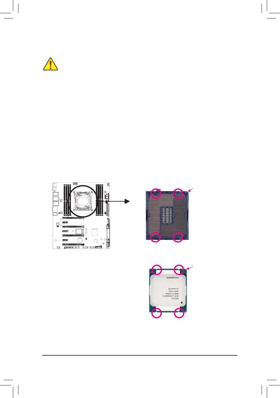
CPU Support for Intel
®
Core
™
i7 processors in the LGA2011-3 package
(GotoGIGABYTE'swebsiteforthelatestCPUsupportlist.)
L3 cache varies with CPU
Chipset Intel
®
X99 Express Chipset
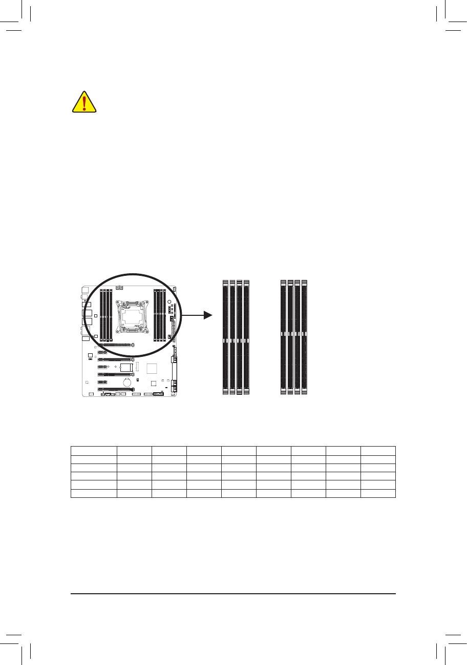
Memory 8 x DDR4 DIMM sockets supporting up to 64 GB of system memory
* DuetoaWindows32-bitoperatingsystemlimitation,whenmorethan4GBofphysical
memoryisinstalled,theactualmemorysizedisplayedwillbelessthanthesizeof
the physical memory installed.
4 channel memory architecture
SupportforDDR42133/1866/1600/1333MHzmemorymodules
Support for non-ECC memory modules
SupportforExtremeMemoryProle(XMP)memorymodules
SupportforRDIMM1Rx8memorymodules(operateinnon-ECCmode)
(GotoGIGABYTE'swebsiteforthelatestsupportedmemoryspeedsandmemory
modules.)
Audio Creative
®
Sound Core 3D chip
Support for Sound Blaster Recon3Di
TI Burr Brown
®
OPA2134operationalamplier
HighDenitionAudio
2/5.1-channel
Support for S/PDIF Out
LAN 1 x Qualcomm
®
AtherosKillerE2201chip(10/100/1000Mbit)(LAN1)
1 x Intel
®
GbELANphy(10/100/1000Mbit)(LAN2)
Wireless
Communication
Module
Wi-Fi802.11a/b/g/n/ac,supporting2.4/5GHzDual-Band
Bluetooth 4.0, 3.0+HS, 2.1+EDR
Support for 11ac wireless standard and up to 867 Mbps data rate
* Actualdataratemayvarydependingonenvironmentandequipment.
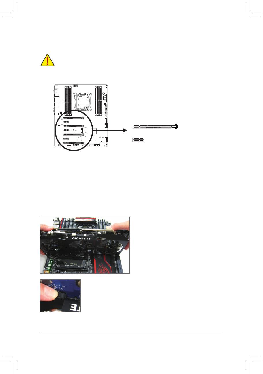
Expansion Slots 2xPCIExpressx16slots,runningatx16(PCIE_1,PCIE_2)
* Foroptimumperformance,ifonlyonePCIExpressgraphicscardistobeinstalled,
be sure to install it in the PCIE_1 slot; if you are installing two PCI Express graphics
cards, it is recommended that you install them in the PCIE_1 and PCIE_2 slots.
2xPCIExpressx16slots,runningatx8(PCIE_3,PCIE_4)
* ThePCIE_4slotsharesbandwidthwiththePCIE_1slot.WhenthePCIE_4slotis
populated, the PCIE_1 slot will operate at up to x8 mode.
* Whenani7-5820KCPUisinstalled,thePCIE_2slotoperatesatuptox8modeand
the PCIE_3 operates at up to x4 mode.
(AllPCIExpressx16slotsconformtoPCIExpress3.0standard.)
3 x PCI Express x1 slots
(ThePCIExpressx1slotsconformtoPCIExpress2.0standard.)
1xM.2Socket1connectorforthewirelesscommunicationmodule(M2_WIFI)
Multi-Graphics
Technology
Support for 4-Way/3-Way/2-Way AMD CrossFire
™
/NVIDIA
®
SLI
™
technology
* The4-WayNVIDIA
®
SLI
™
congurationisnotsupportedwhenani7-5820KCPUis
installed.Tosetupa3-WaySLIconguration,referto"1-6SettingupAMDCrossFire
™
/
NVIDIA
®
SLI
™
Conguration."
Storage Interface Chipset:
- 1xM.2Socket3connector(M2_10G)
- 1 x SATA Express connector
- 6xSATA6Gb/sconnectors(SATA30~5)