Westinghouse LP Conversion Kit, USA Installation guide
- Category
- Cookers
- Type
- Installation guide
This manual is also suitable for

LP & HIGH ALTITUDE LP GAS CONVERSION KIT
FOR INSTALLATIONS IN THE UNITED STATES
FOR R8HE / PPG3HE SERIES, CONDENSING STYLE, GAS / ELECTRIC PACKAGE UNITS
BEFORE THE CONVERSION
IMPORTANT: Please read all instructions before
converting the unit. Pay attention to all safety warnings
and any other special notes highlighted in the manual.
Safety markings are used frequently throughout this
manual to designate a degree or level of seriousness and
should not be ignored. WARNING indicates a potentially
hazardous situation that if not avoided, could result in
personal injury or death. CAUTION indicates a potentially
hazardous situation that if not avoided, may result in minor
or moderate injury or property damage
This conversion kit is only to be used to convert natural gas
uits to LP/Propane gas in the United States. For installations
in Canada, the Canadian conversion kit must be used.
Table 1 is a detailed listing of the components in the LP
gas conversion kit. Please check the contents of the
conversion kit with that of the parts listing, and familiarize
yourself with each component.
WARNING:
All gas piping must conform with local building
codes, or in the absence of local codes, with the
most recent edition of the National Fuel Gas Code
ANSI Z223.1. DO NOT attempt to modify, or tap
into existing gas lines yourself. Fire or explosion
may result causing property damage, personal
injury or loss of life. Failure to follow the safety
warnings exactly could result in serious injury,
death or property damage.
WARNING:
All electrical wiring must comply with the latest
edition of the National Electrical Code ANSI/
NFPA 70. Failure to follow these instructions
could result in possible damage to equipment,
serious personal injury, or death.
IMPORTANT: The installer performing this work assumes
all responsibility for this conversion. These instructions
are primarily intended to assist qualified individuals
experienced in the proper installation of these components.
Some local codes require licensed installation/service
personnel for this type of equipment. Safety should always
be the deciding factor when installing this product and using
common sense plays an important role as well. Improper
installation of the components or failure to follow safety
warnings could result in serious injury, death, or property
damage. After completing the installation, return these
instructions to the Homeowner’s Package for owner-user’s
future reference.
Table 1. LP Gas Conversion Kit
DESCRIPTION
NORDYNE
P/N
QTY
Honeywell Conversion Kit 50033841
(to convert VR9205Q1127)
624805 1
#55 Drill Size Burner Orifice Kit
(contains (7) 661055)
150602 1
#56 Drill Size Burner Orifice Kit
(contains (7) 661056)
272221 1
Conversion Warning Label 703935 1
Conversion Information Label 703942 1
Installation Instructions 709635 1
WARNING
FIRE OR EXPLOSION HAZARD
•Failure to follow safety warnings exactly
could result in serious injury or property
damage.
•Installationandservicemustbeperformed
by a qualified installer, service agency or the
gas supplier.
•Do not store or use gasoline or other
flammable vapors and liquids in the vicinity
of this or any other appliance.
WHAT TO DO IF YOU SMELL GAS
•Donottrytolightanyappliance.
•Donottouchanyelectricalswitch;donot
use any phone in your building.
•Leavethebuildingimmediately.
•Immediatelycallyourgassupplierfroma
neighbors phone. Follow the gas suppliers
instructions.
•Ifyoucannotreachyourgassupplier,call
the fire department.
DO NOT DESTROY. PLEASE READ CAREFULLY &
KEEP IN A SAFE PLACE FOR FUTURE REFERENCE.
USER'S MANUAL

2
CONVERTING TO LP/PROPANE GAS AT
ALTITUDES BETWEEN ZERO & 10,000 FT.
Converting the two-stage gas valve to LP/Propane requires
the replacement of the burner orifices and/or the stem/
spring assembly in the pressure regulator.
Table 2 (page 4), provides the manifold pressure for
altitudes above 2,000 feet.
WARNING:
Shut off the gas supply at the manual gas shutoff
valve, before disconnecting the electrical power.
A fire or explosion may result causing property
damage, personal injury or loss of life. Failure to
follow the safety warnings exactly could result in
serious injury, death or property damage.
WARNING:
To avoid electric shock, personal injury, or death,
turn off the electric power at the disconnect or the
main service panel before making any electrical
connections.
WARNING:
The reduction of input rating necessary for high
altitude installation may only be accomplished
with factory supplied orifices. Do not attempt to
drill out orifices in the field. Improperly drilled
orifices may cause fire, explosion, carbon
monoxide poisoning, personal injury or death.
Before You Convert the Gas Valve
1. Turn the thermostat OFF or to its lowest temperature
setting.
2. Verify the gas supply is shut OFF.
3. Verify the electrical power to the appliance is turned
OFF.
Removing The Burner Orifices
1. Set the thermostat to the OFF position, or its lowest
temperature setting.
2. Shut OFF the gas supply at the manual shutoff valve
located outside of the appliance.
3. Turn off all electrical power to the appliance.
4. Remove the louvered access panel from the burner
compartment.
5. Move the gas valve ON/OFF switch to the OFF position
as shown in Figure 1.
6. Disconnect the 3-wire connector from the gas valve
terminal.
7. Remove the supply gas piping from the gas valve inlet.
8. Carefully remove four screws securing the gas manifold
assembly to the burner assembly.
9. Set the screws aside and remove the gas manifold
assembly from the appliance.
10. Carefully remove the burner orifices from the gas
manifold assembly.
11. Read the rating plate affixed to the appliance to
determine its rated input (Btu/hr) and the size of the
factory installed orifices.
IMPORTANT NOTE: Before installing an orifice, check
the side or face of the orifice for the drill number and
verify that it is the appropriate size.
12. Install the appropriate LP/Propane gas burner orifices
into the gas manifold assembly.
NOTE: To prevent cross threading, hand tighten the
orifices into the gas manifold assembly until snug, then
tighten with a wrench 1/2 to 1 full turn.
WARNING:
Do not use Teflon tape or pipe joint compound
on the orifice threads. The hole in the orifice
may become blocked and cause fire, explosion,
property damage, carbon monoxide poisoning,
personal injury, or death.
13. Reinstall the gas manifold assembly to the burner
assembly with the 4 screws, that were removed earlier.
NOTE: It is important that the center of the orifices are
aligned with the center of the burners.
14. Reconnect the gas piping to the gas valve inlet.
15. Reconnect the 3-wire connector to the gas valve
terminal.
Converting the Gas Valve
IMPORTANT NOTES:
• When converting to LP/Propane gas from natural
gas, the springs from gas valve must be replaced
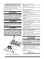
Figure 1. Burner & Manifold Assembly
GAS INLET
ON / OFF
SWITCH
BURNER
ASSEMBLY
SCREWS (X4)
GAS
MANIFOLD
BURNER ORIFICES
3-PIN
CONNECTOR
BURNERS

3
2. Check all gas connections for leaks with a soap and
water solution. If the solution bubbles there is a gas
leak which must be corrected.
3. Turn on the electrical power to the appliance.
4. Place the gas valve ON / OFF switch to the ON position.
See Figure 2.
5. Set the thermostat above room temperature to begin
the heating cycle of the furnace.
6. Check that the furnace ignites and operates properly.
Refer to the installation instructions provided with the
unit for the normal operating sequence.
7. After ignition, visually inspect the burner assembly to
ensure that the flame is drawn directly into the center of
the heat exchanger tube. In a properly adjusted burner
assembly, the flame color should be blue with some light
yellow streaks near the outer portions of the flame.
NOTE: The ignitor may not ignite the gas until all air is
bled from the gas line. If the ignition control locks out,
turn the thermostat to its lowest setting and wait one
minute then turn the thermostat above room temperature
and the ignitor will try again to ignite the main burners.
This process may have to be repeated several times
before the burners will ignite. After the burners are lit,
check all gas connections for leaks again with the soap
and water solution.
Measuring the Manifold Pressure
The manifold pressure must be measured by installing a
pressure gauge (Manometer, Magnehelic Meter, etc.) to
the outlet end of the gas valve as follows:
1. Turn off all electrical power to the appliance.
2. Shut OFF the gas supply at the manual shutoff valve
located outside of the appliance.
3. Using a 3/16” Allen wrench, remove the manifold
pressure tap plug located on the outlet side of the gas
valve. See Figure 2.
4. Install an 1/8” NPT pipe thread fitting, that is compatible
with a Manometer or similar pressure gauge.
5. Connect the Manometer or pressure gauge to the
manifold pressure tap.
6. Set the room thermostat above room temperature to
start the furnace.
7. Allow the furnace to operate for 3 minutes and then
check the manifold pressure. Compare the measured
value with the value shown in Table 2 (page 4). If the
manifold pressure is not set to the appropriate pressure,
then it must be adjusted.
Adjusting the Manifold Pressure
NOTE: Adjustments must be made to both LOW & HIGH
fire settings when converting two-stage gas valves. Refer
to Table 2 for manifold pressures.
1. Remove the cap screw (Figure 2, page 4).
2. Using a screwdriver or Allen wrench (where appropriate),
slowly turn the adjustment screw till the appropriate
manifold pressure listed in Table 2 is achieved.
NOTE: Turning the screw clockwise increases the
pressure, turning the screw counter-clockwise
decreases the pressure. To prevent the screw from
GAS PRESSURE ADJUSTMENT
Measuring the Supply Gas Pressure
1. Turn OFF the gas supply at the manual valve located
on the outside of the unit.
2. Using a 3/16” Allen wrench, remove the plug from the
inlet pressure tap (INLET side of gas valve). See Figure
2.
3. Install an 1/8” NPT pipe thread fitting, that is compatible
with a Manometer or similar pressure gauge.
4. Connect the Manometer or pressure gauge to the Inlet
Pressure Tap.
5. Turn ON the main gas supply at the manual valve.
6. Check and adjust the incoming gas line pressure to
11.0-14.0 inches Water Column for LP/Propane gas.
7. Turn OFF the gas supply at the manual valve.
8. Disconnect the Manometer or pressure gauge.
9. Remove the NPT fitting and reinstall the INLET pressure
tap plug. Hand tighten the plug first to prevent cross-
threading. Tighten with 3/16 Allen wrench.
Lighting & Adjustment of the Appliance
WARNING:
FIRE OR EXPLOSION HAZARD
Failure to follow safety warnings exactly could
result in serious injury or property damage.
Never test for gas leaks with an open flame. Use
a commercially available soap solution made
specifically for the detection of leaks to check
all connections. A fire or explosion may result
causing property damage, personal injury or
loss of life.
1. Turn ON the manual gas valve, located on the outside
of the unit to the ON position.
by the larger springs from the kit. The LP/Propane
springs for both HIGH & LOW fire are the same
size, shape and color. See Figure 2 (page 4).
• UseonlyaTorx-25or3/16”atheadscrewdriver
when removing adjustment screws or during
pressure adjustment.
1. Remove the HIGH fire cap screw. See Figure 2.
2. Remove and discard the HIGH fire adjustment screw
from the gas valve.
3. Remove the spring from the gas valve and discard.
4. Install a larger spring from the conversion kit.
5. Install a new adjusting screw from the kit.
6. Repeat steps 1 - 5 for replacement of the LOW fire
spring and adjustment screw.
7. Check and adjust the regulator setting. See Gas Pressure
Adjustment Section.
8. Reinstall the cap screws on the HIGH and LOW
regulators. Plastic replacement cap screws are provided
in the conversion kit.
9. Affix the yellow label from the spring conversion kit to
the gas valve.

backing all the way out from the valve, turn the screw
slowly.
3. Replace and tighten the cap screw or the plastic cap
over the adjustment screw.
Removing the Manometer / Pressure Gauge
After the manifold pressure is properly adjusted, the
Manometer or pressure gauge must be removed from
the gas valve.
1. Turn the thermostat to its lowest setting.
2. Turn OFF the main gas supply to the unit at the manual
shut-off valve, which is located outside of the unit.
3. Turn OFF all of the electrical power supplies to the unit.
4. Remove the pressure gauge adapter from the gas valve
and replace it with the 1/8” NPT manifold pressure plug
that had been removed earlier. NOTE: Make sure the
plug is tight and not cross-threaded.
5. Turn ON the electrical power to the unit.
6. Turn ON the main gas supply to the unit at the manual
shut-off valve.
COMPLETING THE CONVERSION
WARNING:
Do not alter or remove the original rating plate
from the furnace.
1. Attach the following labels:
• Theconversionwarninglabel(P/N703935)should
be affixed to the outside of the unit door.
• The conversion information label (P/N 703942)
should be affixed on the inside of the control area
or the louvered access panel.
• Verifytheyellowlabelfromthespringconversion
kit is affixed to the gas valve.
NOTE: Each label should be prominently visible after
installation.
2. Reinstall the appliance door.
3. Run the appliance through 3 complete cycles to assure
proper operation.
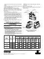
Figure2.Two-StageGasValve
(ModelVR9205Q1127)
Inlet Pressure Ta p
Manifold
pressure Ta p
ON/OFF
Switch
High Fire
Cap Screw
High Fire
Adjustment Screw
Low Fire
Cap Screw
Low Fire
Adjustment Screw
Spring
Spring
Table2.LiquidPropaneConversionChart(2-StageModels)
7096350(NEW)
Specifications & illustrations subject to change without notice or incurring obligations.
O’ Fallon, MO | Printed in U.S.A. (09/13)
MODEL
NUMBER
R8HE/ PPG3HE
GAS
VALVE
SETTING
INPUT
(BTUH)
ALTITUDE ABOVE SEA LEVEL
0to1,999FT
2,000 to
2,999FT
3,000 to
4,999FT
5,000to
5,999FT
6,000to
7,999FT
8,000 to
10,000 FT
ORIFICE
SIZE
MANIFOLD
PRESSURE
ORIFICE
SIZE
MANIFOLD
PRESSURE
ORIFICE
SIZE
MANIFOLD
PRESSURE
ORIFICE
SIZE
MANIFOLD
PRESSURE
ORIFICE
SIZE
MANIFOLD
PRESSURE
ORIFICE
SIZE
MANIFOLD
PRESSURE
-X24K060X
-X30K060X
High 60,000
55
10.0
55
9.0
55
8.0
56
10.0
56
9.0
56
8.0
Low 39,000 4.2 3.8 3.6 4.2 3.8 3.6
-X36K080X
-X42K080X
High 80,000
55
10.0
55
9.0
55
8.0
56
10.0
56
9.0
56
8.0
Low 52,000 4.2 3.8 3.6 4.2 3.8 3.6
-X48K100X
-X60K100X
High 100,000
55
10.0
55
9.0
55
8.0
56
10.0
56
9.0
56
8.0
Low 65,000 4.2 3.8 3.6 4.2 3.8 3.6
-
 1
1
-
 2
2
-
 3
3
-
 4
4


Westinghouse LP Conversion Kit, USA Installation guide
- Category
- Cookers
- Type
- Installation guide
- This manual is also suitable for
Ask a question and I''ll find the answer in the document
Finding information in a document is now easier with AI
Related papers
-
Broan FG7MQ Installation guide
-
Westinghouse FG7S(C,L) Installation guide
-
Broan PPG3HE Installation guide
-
-
Broan PPG3HE-A, Single Phase Installation guide
-
-
Broan G7 LP Conversion Kit (Canada) Installation guide
-
Broan R6GD Canadian LP Conversion Kit - 904091A Installation guide
-
-
Other documents
-
Thermo Pride AOPS7749, AOPS7745 Owner's manual
-
Intertherm FG7S(C,L) Installation guide
-
Broan MG2S Installation guide
-
Reznor R8HE Series Installation guide
-
-
-
Unbranded LP Conversion Kit 150/180 Installation guide
-
-
-