Page is loading ...

The Stylos Speaker System
User's Manual
THE ELECTROSTATIC TECHNOLOGY

Page 2
Stylos User's Manual

Page 3
Stylos User's Manual
Introduction 4
The Electrostatic Concept 5
History 6
Martin-Logan Exclusives 8
Installation Options 10
Operation 11
Placement/Listening Position 12
On-Wall Installation 13
Room Acoustics 16
Home Theatre 20
Questions 21
Troubleshooting 22
Recommended Music 23
Glossary 24
Stylos Specifications 26
Important
Contents
Your Stylos
speakers are provided with an automatic
Limited 90 Day Warranty coverage.
You have the option, at no additional charge, to receive
Limited 3 Year Warranty coverage. To obtain Limited 3
Year Warranty coverage you need only complete and
return the Certificate of Registration that was included
with your speakers along with a copy of your invoice to
Martin-Logan, within 30 days of purchase.
Martin-Logan may not honor warranty serviceMartin-Logan may not honor warranty service
Martin-Logan may not honor warranty serviceMartin-Logan may not honor warranty service
Martin-Logan may not honor warranty service
claims unless we have a completed Warrantyclaims unless we have a completed Warranty
claims unless we have a completed Warrantyclaims unless we have a completed Warranty
claims unless we have a completed Warranty
Registration card on file!Registration card on file!
Registration card on file!Registration card on file!
Registration card on file!
Should you be using your Martin-Logan product in a
country other than the one in which it was originally
purchased, we ask that you note the following:
1) The appointed Martin-Logan distributor for any given
country is responsible for warranty servicing only on
units distributed by or through it in that country in
accordance with its applicable warranty.
2) Should a Martin-Logan product require servicing in a
country other than the one in which it was originally
purchased, the end user may seek to have repairs
performed by the nearest Martin-Logan distributor,
subject to that distributor's local servicing policies,
but all cost of repairs (parts, labor, transportation)
must be born by the owner of the Martin-Logan
product.
3) If you relocate to a country, other than where you
purchased your Martin-Logan's, after owning your
speakers for 6 months your warranty may be
transferable. Contact Martin-Logan for details.
If you did not receive a Certificate of Registration with
your Stylos
speakers you cannot be assured of having
received new units. If this is the case, please contact
your Authorized Martin-Logan dealer.

Page 4
Stylos User's Manual
Introduction
Congratulations, you have invested in one of the world’s
premier loudspeaker systems!
The result of 3 years of research and more than 40 fully
functional prototypes, the Stylos represents the latest
advancements in electrostatic technology and speaker
placement flexibility.
Combining our proprietary curvilinear electrostatic
transducer with a compact, but powerful woofer, we have
designed a product, in one package, that reproduces
music with uncompromised electrostatic clarity and
extended bass, yet can be mounted on or in a wall
requiring no floor space.
All materials in your new Stylos speakers are of the
highest quality to provide years of enduring enjoyment
and deepening respect. The cabinetry is constructed from
a special high-density hardwood powderboard for
structural integrity and is finished with a durable and
attractive matte surface finish.
Through rigorous testing, the curvilinear electrostatic
panel has proven itself to be one of the most durable and
reliable transducers available today. Fabricated from a
specially tooled, high-grade steel, the panel is then
coated with a special high dielectric compound that is
applied via a proprietary electrostatic deposition process.
This panel assembly houses a membrane 0.0005 of an
inch thick! Ruggedly constructed and insulated, as much
as 200 watts of continuous power has driven the Stylos
energized diaphragm into massive excursions with no
deleterious effects.
Please read and follow these instructions as you initially
install the Stylos
speakers into your system. These
instructions are important and will prevent you from
experiencing any delay, frustration, or system damage
which might occur in a trial-and-error procedure.
The other sections of your
User’s Manual User’s Manual
User’s Manual User’s Manual
User’s Manual will explain in
detail the operation of your Stylos
speakers and the
philosophy applied to their design. A clear understanding
of your speakers will insure that you obtain maximum
performance and pleasure from this most exacting
transducer.
Happy Listening!

Page 5
Stylos User's Manual
The Electrostatic Concept
How can sound be reproduced by something that you are
able to see through? Electrostatic energy makes this
possible.
Where the world of traditional loudspeaker technology
deals with cones, domes, diaphragms and ribbons that
are moved with magnetism, the world of electrostatic
loudspeakers deals with charged electrons attracting and
repelling each other.
To fully understand the electrostatic concept, some
background information will be helpful. Remember when
you learned, in a science or physics class, that like
charges repel each other and
opposite charges attract each
other? Well, this principle is the
foundation of the electrostatic
concept.
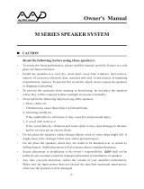
An electrostatic transducer
consists of three pieces: the
stators, the diaphragm and the
spacers.
See Figure 1
. The
diaphragm is what actually
moves to excite the air and
create music. The stator's job is
to remain stationary, hence the
word stator, to provide a
reference point for the moving
diaphragm. The spacers
provide the diaphragm with a
fixed distance in which to move
between the stators.
As your amplifier sends music
signals to an electrostatic
speaker, these signals are
changed into two high-voltage
signals that are equal in
strength but opposite in polarity.
These high voltage signals are
then applied to the stators. The
resulting electrostatic field,
created by the opposing high
voltage on the stators, works
simultaneously with and
against the diaphragm,
consequently moving it back
and forth, producing music. This
Magnet
An Electromagnetic TransducerAn Electromagnetic Transducer
An Electromagnetic TransducerAn Electromagnetic Transducer
An Electromagnetic Transducer
Surround
Cone
Dust Cap
Voice Coil Former
Magnet Assembly
Magnetic GapVoice Coil
Basket Assembly
Figure 2.Figure 2.
Figure 2.Figure 2.
Figure 2. Cut away view of a typical moving coil driver.
Notice the complexity due to the high number of parts.
Spider
An Electrostatic TransducerAn Electrostatic Transducer
An Electrostatic TransducerAn Electrostatic Transducer
An Electrostatic Transducer
Stator
Spacer
Diaphragm
Figure 1Figure 1
Figure 1Figure 1
Figure 1. Cut away view of an electrostatic transducer.
Notice the simplicity due to minimal parts usage.
technique is known as push-pull operation and is a major
contributor to the sonic purity of the electrostatic concept
due to its exceptional linearity and low distortion.
Since the diaphragm of an electrostatic speaker is
uniformly driven over its entire area, it can be extremely
light and flexible. This allows it to be very responsive to
transients, thus perfectly tracing the music signal. As a
result, great delicacy, nuance and clarity is possible.
When you look at the problems of traditional electromag-
netic drivers, you can easily see why this is so beneficial.
The cones and domes which are used in traditional
electromagnetic drivers cannot be driven uniformly
because of their design.
Cones are driven only at the
apex. Domes are driven at
their perimeter. As a result,
the rest of the cone or dome
is just "along for the ride". The
very concept of these drivers
require that the cone or dome
be perfectly rigid, damped
and massless. Unfortunately
these conditions are not
available in our world today.
To make these cones and
domes move, all electromag-
netic drivers must use voice
coils wound on formers,
spider assemblies, and
surrounds to keep the cone
or dome in position.
See
Figure 2.
These pieces, when
combined with the high mass
of the cone or dome materials
used, make it an extremely
complex unit with many
weaknesses and potential for
failure. These faults contrib-
ute to the high distortion
products found in these
drivers and is a tremendous
disadvantage when you are
trying to change motion as
quickly and as accurately as
a loudspeaker must (40,000
times per second!).

Page 6
Stylos User's Manual
History
In the late 1800’s, any loudspeaker was considered
exotic. Today, most of us take the wonders of sound
reproduction for granted.
It was 1880 before Thomas Edison had invented the first
phonograph. This was a horn-loaded diaphragm that was
excited by a playback stylus. In 1898, Sir Oliver Lodge
invented a cone loudspeaker, which he referred to as a
“bellowing telephone”, that was very similar to the
conventional cone loudspeaker drivers that we know
today. However, Lodge had no intention for his device to
reproduce music, because in 1898 there was no way to
amplify an electrical signal! As a result, his speaker had
nothing to offer over the acoustical gramophones of the
period. It was not until 1906 that Dr. Lee DeForrest
invented the triode vacuum tube. Before this, an electrical
signal could not be amplified. The loudspeaker, as we
know it today, should have ensued then, but it did not.
Amazingly, it was almost twenty years before this would
occur.
In 1921, the electrically cut phonograph record became a
reality. This method of recording was far superior to the
mechanically cut record and possessed almost 30 dB of
dynamic range. The acoustical gramophone couldn't
begin to reproduce all of the information on this new disc.
As a result, further developments in loudspeakers were
needed to cope with this amazing new recording me-
dium.
By 1923, Bell Telephone Laboratories made the decision
to develop a complete musical playback system consist-
ing of an electronic phonograph and loudspeaker to take
advantage of the new recording medium. Bell Labs
assigned the project to two young engineers, C.W. Rice
and E.W. Kellogg.
Rice and Kellogg had a well equipped laboratory at their
disposal. This lab possessed a vacuum tube amplifier
with an unheard of 200 watts, a large selection of the new
electrically cut phonograph records and a variety of
loudspeaker prototypes that Bell Labs had been collect-
ing over the past decade. Among these were Lodge’s
cone, a speaker that used compressed air, a corona
discharge (plasma) speaker, and an electrostatic
speaker.
After a short time, Rice and Kellogg had narrowed the
field of "contestants" down to the cone and the electrostat.
The outcome would dictate the way that future genera-
tions would refer to loudspeakers as being either
"conventional", or "exotic".
Bell Laboratory’s electrostat was something to behold.
This enormous bipolar speaker was as big as a door. The
diaphragm, which was beginning to rot, was made of the
membrane of a pigs intestine that was covered with fine
gold leaf to conduct the audio signal.
When Rice and Kellogg began playing the new electri-
cally cut records through the electrostat, they were
shocked and impressed. The electrostat performed
splendidly. They had never heard instrumental timbres
reproduced with such realism. This system sounded like
real music rather than the honking, squawking rendition
of the acoustic gramophone. Immediately, they knew they
were on to something big. The acoustic gramophone was
destined to become obsolete.
Due to Rice and Kellogg's enthusiasm, they devoted a
considerable amount of time researching the electrostatic
design. However, they soon encountered the same
difficulties that even present designers face; planar
speakers require a very large surface area to reproduce
the lower frequencies of the audio spectrum. Because the
management at Bell Labs considered large speakers
unacceptable, Rice and Kellogg's work on electrostatics
would never be put to use for a commercial product.
Reluctantly, they advised the Bell management to go with
the cone. For the next thirty years the electrostatic design
lay dormant.
During the Great Depression of the 1930's, consumer
audio almost died. The new electrically amplified
loudspeaker never gained acceptance, as most people
continued to use their old Victrola-style acoustic gramo-
phones. Prior to the end of World War II, consumer audio
saw little, if any, progress. However, during the late
1940's, audio experienced a great rebirth. Suddenly there
was tremendous interest in audio products and with that,
a great demand for improved audio components. No
sooner had the cone become established than it was
challenged by products developed during this new
rebirth.
In 1947, Arthur Janszen, a young Naval engineer, took
part in a research project for the Navy. The Navy was
interested in developing a better instrument for testing

Page 7
Stylos User's Manual
microphone arrays. The test instrument needed an
extremely accurate speaker, but Janszen found that the
cone speakers of the period were too nonlinear in phase
and amplitude response to meet his criteria. Janszen
believed that electrostats were inherently more linear
than cones, so he built a model using a thin plastic
diaphragm treated with a conductive coating. This model
confirmed Janszen's beliefs, for it exhibited remarkable
phase and amplitude linearity.
Janszen was so excited with the results that he continued
research on the electrostatic speaker on his own time. He
soon thought of insulating the stators to prevent the
destructive effects of arcing. By 1952 he had an electro-
static tweeter element ready for commercial production.
This new tweeter soon created a sensation among
American audio hobbyists. Since Janszen's tweeter
element was limited to high frequency reproduction, it
often found itself used in conjunction with woofers, most
notably, woofers from Acoustic Research. These systems
were highly regarded by all audio enthusiasts.
As good as these systems were, they would soon be
surpassed by another electrostatic speaker.
In 1955, Peter Walker published three articles on
electrostatic loudspeaker design in
Wireless World
, a
British electronics magazine. In these articles Walker
demonstrated the benefits of the electrostatic loud-
speaker. He explained that electrostatics permit the use
of diaphragms that are low in mass, large in area, and
uniformly driven over their surfaces by electrostatic
forces. Due to these characteristics, electrostats have the
inherent ability to produce a wide bandwidth, flat fre-
quency response with distortion products being no
greater than the electronics driving them.
By 1956 Walker backed up his articles by introducing a
consumer product, the now famous Quad ESL. This
speaker immediately set a standard of performance for
the audio industry due to its incredible accuracy. How-
ever, in actual use the Quad had a few problems. It could
not play very loud, it had poor bass performance, it
presented a difficult load that some amplifiers did not like,
its dispersion was very directional, and its power han-
dling was limited to around 70 watts. As a result, many
people continued to use box speakers with cones.
In the early 1960's Arthur Janszen joined forces with the
KLH loudspeaker company and together they introduced
the KLH 9. Due to the large size of the KLH 9, it did not
have as many limitations as the Quad. The KLH 9 could
play markedly louder and lower in frequency than the
Quad ESL. Thus a rivalry was born.
Janszen continued to develop electrostatic designs. He
was instrumental in the design of the Koss Model One,
the Acoustech, and the Dennesen speakers. Roger West,
the chief designer of the JansZen Corporation became
the president of Sound Lab. When JansZen Corporation
was sold, the RTR loudspeaker company bought half of
the production tooling. This tooling was used to make the
electrostatic panels for the Servostatic, a hybrid electro-
static system that was Infinity's first speaker product. Other
companies soon followed; each with their own unique
applications of the technology. These include Acoustat,
Audiostatic, Beverage, Dayton Wright, Sound Lab, and
Stax to name a few.
Electrostatic speakers have progressed and prospered
because they actually do what Peter Walker claimed they
would. The limitations and problems experienced in the
past were not inherent to the electrostatic concept. They
were related to the applications of these concepts.
Today, these limitations have been addressed. Advance-
ments in materials due to the U.S. space program give
designers the ability to harness the superiority of the
electrostatic principle. Today's electrostats use advanced
insulation techniques or provide protection circuitry. The
poor dispersion properties of early models have been
addressed by using delay lines, acoustical lenses,
multiple panel arrays or, as in our own products, by
curving the diaphragm. Power handling and sensitivity
have been increased.
These developments allow the consumer the opportunity
to own the highest performance loudspeaker products
ever built. It's too bad Rice and Kellogg were never able
to see just how far the technology would be taken.

Page 8
Stylos User's Manual
Martin-Logan Exclusives
Full Range OperationFull Range Operation
Full Range OperationFull Range Operation
Full Range Operation
The most significant advantage of Martin-Logan's
exclusive transducer technology reveals itself when you
compare it to examples of other loudspeaker products on
the market today.
The Stylos uses no crossover networks above 700 Hz
because they are not needed. It consists of a single,
seamless electrostatic membrane reproducing all
frequencies above 700 Hz simultaneously. How is this
possible?
First, it is important to understand that music is not
composed of separate high, mid and low frequency
pieces. In fact, music is comprised of a single complex
waveform with all frequencies interacting simultaneously.
The electrostatic transducer of
the Stylos essentially acts as
an exact opposite of the
microphones used to record
the original event. A micro-
phone, which is a single
working element, transforms
acoustic energy into an
electrical signal that can be
amplified or preserved by
some type of storage media.
The Stylos
electrostatic
transducer transforms
electrical energy from your
amplifier into acoustical
energy with a single mem-
brane.
Upon looking carefully at a
traditional magnetic driver (I.e.
dynamic, ribbon, induction),
no single unit can reproduce
the full range of frequencies.
Instead, these drivers must be
designed to operate within
narrow areas of music and
then combined electrically so
that the sum of the parts
equals the total signal. While this sounds nice in theory, a
different story unfolds in real-world conditions.
In order to use multiple drivers, a crossover network is
enlisted to divide the complex musical signal into the
separate parts (usually highs, mids, and lows) that each
specific driver was designed to handle. Unfortunately,
due to the phase relationships that occur within all
crossover networks and during the acoustical recombina-
tion process, nonlinearities and severe degradation of the
music signal takes place in the ear's most "critical zone",
the crossover between the tweeter and midrange.
See
Figure 1
.
So, music in the "critical zone" becomes delayed in time.
These delays can be picked-
up by your ear and result in
poor imaging and ambience
cues. Voices lose their
complex harmonies and
sound less like the vocalist
and more like a stereo
speaker.
The Stylos electrostaticThe Stylos electrostatic
The Stylos electrostaticThe Stylos electrostatic
The Stylos electrostatic
transducer can single-transducer can single-
transducer can single-transducer can single-
transducer can single-
handedly reproduce allhandedly reproduce all
handedly reproduce allhandedly reproduce all
handedly reproduce all
audio frequencies aboveaudio frequencies above
audio frequencies aboveaudio frequencies above
audio frequencies above
700 Hz simultaneously.700 Hz simultaneously.
700 Hz simultaneously.700 Hz simultaneously.
700 Hz simultaneously.
The crossover phase disconti-
nuities that are associated
with traditional tweeter,
midrange/woofer systems are
eliminated in the Stylos. This
results in a
dramaticdramatic
dramaticdramatic
dramatic
improvement in imagingimprovement in imaging
improvement in imagingimprovement in imaging
improvement in imaging
and staging performanceand staging performance
and staging performanceand staging performance
and staging performance
due to the minutelydue to the minutely
due to the minutelydue to the minutely
due to the minutely
accurate phase relation-accurate phase relation-
accurate phase relation-accurate phase relation-
accurate phase relation-
ship of the full-rangeship of the full-range
ship of the full-rangeship of the full-range
ship of the full-range
panel wave launch.panel wave launch.
panel wave launch.panel wave launch.
panel wave launch.
Critical ZoneCritical Zone
Critical ZoneCritical Zone
Critical Zone
700 - 20kHz700 - 20kHz
700 - 20kHz700 - 20kHz
700 - 20kHz
TweeterTweeter
TweeterTweeter
Tweeter
MidrangeMidrange
MidrangeMidrange
Midrange
WooferWoofer
WooferWoofer
Woofer
Critical ZoneCritical Zone
Critical ZoneCritical Zone
Critical Zone
700 - 20kHz700 - 20kHz
700 - 20kHz700 - 20kHz
700 - 20kHz
WooferWoofer
WooferWoofer
Woofer
StylosStylos
StylosStylos
Stylos
ElectrostaticElectrostatic
ElectrostaticElectrostatic
Electrostatic
TransducerTransducer
TransducerTransducer
Transducer
Martin-Logan
StylosStylos
StylosStylos
Stylos Loudspeaker
Conventional Loudspeaker
Figure 1. Figure 1.
Figure 1. Figure 1.
Figure 1. Illustrates how a conventional speaker system
must use a crossover network that has negative affects
on the musical performance, unlike the Stylos which
needs no crossover networks in the "critical zone".

Page 9
Stylos User's Manual
Vapor Deposited FilmVapor Deposited Film
Vapor Deposited FilmVapor Deposited Film
Vapor Deposited Film
The diaphragm material used in all Martin-Logan
speakers employs an extremely sophisticated vapor
deposited conductive polymer membrane. A proprietary
conductive compound is vaporized then electrostatically
driven into the surface of the polymer film in a vacuum
chamber. This process allows an optically transparent
membrane, adds no mass to the diaphragm and is
extremely uniform in its surface resistivity characteristics.
This uniform surface resistivity controls the electrostatic
charge on the diaphragm surface and regulates its
migration. As a result, no discharging or “arcing” can
occur.
Transducer IntegrityTransducer Integrity
Transducer IntegrityTransducer Integrity
Transducer Integrity
All Martin-Logan transducers begin with two pieces of
high grade, cold rolled steel. These steel pieces are then
custom perforated and insulated with an exotic composite
coating. This proprietary coating insulates the stator to 3
times its actual needed working voltage and gives the
Stylos a wide margin of safe operation. In addition to the
electrical insulation properties, this coating also provides
the Stylos with a durable, attractive finish that dampens
the steel to prevent ringing. The finished metal plates are
curved into a 30 degree arc. Placed between them is our
exclusive vapor deposited diaphragm and spacers. This
assembly is then bonded together with aerospace
adhesives whose strength is so great that it is commonly
used as an alternative to welding.
The result of these advanced technologies is a trans-
ducer that is attractive, durable, highly rigid, well damp-
ened, and neutral.
Mechanical/AcousticalMechanical/Acoustical
Mechanical/AcousticalMechanical/Acoustical
Mechanical/Acoustical
Tone ShapingTone Shaping
Tone ShapingTone Shaping
Tone Shaping
The clear Lexan
®
panels on the back of the Stylos stator
are the key elements of an innovative pressure compen-
sation technology. Martin-Logan is able to tone-shape the
diaphragm + or - 6dB without the use of an insertion loss
crossover. The advantage of this system is a high
efficiency driver with wide bandwidth capabilities of
dimensions which are easily integrated into a domestic
environment.
Curvilinear Line SourceCurvilinear Line Source
Curvilinear Line SourceCurvilinear Line Source
Curvilinear Line Source
Since the beginning of audio, achieving smooth full range
dispersion has long been a problem for all loudspeaker
designers. Large panel transducers present even more of
a challenge because the larger the panel, the more
directional the dispersion pattern becomes.
Full range electrostatics have always been one of the
most complex transducers because they attain their full
range capabilities via a large surface area. It looked as if
they were in direct conflict to smooth dispersion and
almost every attempt to correct this resulted in either poor
dispersion or a serious compromise in sound quality.
After extensive research, Martin-Logan engineers
discovered an elegantly simple solution to achieve a
smooth pattern of dispersion without degrading sound
quality. By curving the horizontal plane of the electrostatic
transducer, a controlled horizontal dispersion pattern
could be achieved, yet the purity of the almost massless
electrostatic diaphragm remained uncompromised. After
creating this technology, we developed the production
capability to bring this technology out of the laboratory
and into the market place.
You will find this proprietary Martin-Logan technology
used in all of our products. It is one of the many reasons
behind our reputation for high quality sound with practical
usability. This is also why you see the unique "see
through" cylindrical shape of all Martin-Logan products.

Page 10
Stylos User's Manual
Installation Options
The most difficult part of installing your Stylos is deciding which of the available installation options will best integrate into
your home. Here are some examples of how each of the 4 Stylos installation kits can be used. The only thing to add is your
imagination.
On a StandOn a Stand
On a StandOn a Stand
On a Stand
- When the wall behind the speaker will not allow speaker
mounting, i.e. book case or window
- If there is a high possibility the speakers will be fre-
quently moved
- As a dipole side channel for a home theatre system
Hardware required: Optional Stylos stand kit
In WallIn Wall
In WallIn Wall
In Wall
- When not being seen is as important as sounding great
- Allows finishing the Stylos grill to match the wall color
- Most complicated installation
Hardware required: Optional Stylos in-wall kit, certified
electrician to provide in-wall A.C. in accordance to code,
in-wall speaker cable accessibility
On A Side WallOn A Side Wall
On A Side WallOn A Side Wall
On A Side Wall
- The front wall is a window or book case
- The room is long and narrow
- A dipole side channel for home theatre
Hardware required: Optional Stylos side-mount kit
On WallOn Wall
On WallOn Wall
On Wall
- When the wall in front of you is ideal for speaker
placement but floor space is not available
- To flank a projection screen, window or fireplace
- Fit inside a cabinet
Hardware required: Standard wall-mount kit included with
all Stylos

Page 11
Stylos User's Manual
Operation
AC Power ConnectionAC Power Connection
AC Power ConnectionAC Power Connection
AC Power Connection
Because your Martin-Logan Stylos
use an internal power
supply to energize their electrostatic cells with high-
voltage DC, they must be connected to an AC power
source. For this reason they are provided with the proper
IEC standard power cords. These cords should be firmly
inserted into any convenient AC wall outlet. Extension
cords may be used, if necessary, since the AC power
requirement of the speaker is extremely small (less than 5
watts). The Stylos have been designed to remain on
continuously and should remain connected to a continu-
ous AC power source. As mentioned earlier, power
consumption of the Stylos is very small and the life
expectancy of its components will not be reduced by
continuous operation.
The power cord should not be installed, re-The power cord should not be installed, re-
The power cord should not be installed, re-The power cord should not be installed, re-
The power cord should not be installed, re-
moved, or left detached from the speaker whilemoved, or left detached from the speaker while
moved, or left detached from the speaker whilemoved, or left detached from the speaker while
moved, or left detached from the speaker while
the other end is connected to an AC powerthe other end is connected to an AC power
the other end is connected to an AC powerthe other end is connected to an AC power
the other end is connected to an AC power
source.source.
source.source.
source.
Your Stylos speakers are wired for the power service
supplied in the country of original consumer sale unless
manufactured on special order. The AC power rating
applicable to a particular unit is specified both on the
packing carton and on the serial number plate attached to
the speaker.
If you remove your Stylos speakers from the country of
original sale, be certain that AC power supplied in any
subsequent location is suitable before connecting and
operating the speakers. Substantially impaired perform-
ance or severe damage may occur to a Stylos speaker if
operation is attempted from an incorrect AC power
source.
If your home is not equipped with three-prong wall
outlets, you may use “cheater” plugs to connect the
speakers to AC power. These may be obtained at your
dealer or any hardware department.
Signal ConnectionSignal Connection
Signal ConnectionSignal Connection
Signal Connection
Connections are done at the
Signal InputSignal Input
Signal InputSignal Input
Signal Input section on
the bottom electronics panel of the Stylos. Use spade
connectors for optimum contact and ease of installation.
Make certain that all of your connections are tight.
Be consistent when connecting the speaker cables to the
Signal Input Signal Input
Signal Input Signal Input
Signal Input terminals. Take care to assign the same
color cable lead to the (+) terminal on both the left and
right channel speakers. If bass is nonexistent and you
cannot discern a tight, coherent image, you may need to
reverse the (+) and (-) leads on one speaker to bring the
system into proper polarity.
Use the best speaker cables you can! The length and
type of speaker cable used in your system will have an
audible effect. Under no circumstance should a wire of
gauge higher (thinner) than #14 be used. In general, the
longer the length used, the greater the necessity of a
lower gauge, and the lower the gauge, the better the
sound, with diminishing returns setting in around #8 to
#12.
A variety of speaker cables are now available whose
manufacturers claim better performance than with
standard heavy gauge wire. We have verified this in
some cases, and the improvements available are often
more noticeable than the differences between wires of
different gauge.
We would also recommend, if possible, that short runs of
speaker cable connect the power amplifier(s) and
speakers and that high quality long interconnect cables
be used to connect the preamplifier and power amplifier.
This results in the power amplifiers being close to the
speakers, which may be practically or cosmetically
difficult, but if the length of the speaker cables can be
reduced to a few meters, sonic advantages may be
obtained. The effects of cables may be masked if the
equipment is not of high quality.

Page 12
Stylos User's Manual
Distance fromDistance from
Distance fromDistance from
Distance from
the Side Wthe Side W
the Side Wthe Side W
the Side W
allall
allall
all
For the most even bass response, we
recommend that the center of the
Stylos be greater than 16" from the
side-wall. Locating the Stylos closer to
the corner may reinforce certain bass
notes.
Placement/Listening Position
Distance from theDistance from the
Distance from theDistance from the
Distance from the
FloorFloor
FloorFloor
Floor
Using ergometric data of the 95th%
male (6’1") and the 5th% female
(4’11) placed on the average height
seat of living room furniture, we
recommend a floor to speaker
distance of 7" inches. This will provide
excellent frequency response if you
are sitting or standing. However, if this
is not practical, the speaker can be
tipped in the brackets to compensate
for a 3 inch variation in mounting
height.

Page 13
Stylos User's Manual
Installation ProcedureInstallation Procedure
Installation ProcedureInstallation Procedure
Installation Procedure
After determining the best location for
your speakers, based on your room
requirements and our recommenda-
tions, you are ready to begin
installation.
Tools required:
1 - M-L Wall Mount Kit:
4 - wall brackets
1 - Stylos template
16 - zip anchors
16 - #8X3/4" screws
1 - plumb line
2 - 1/2" screws with knobs
2 - 1/2" allen head cap screws
4 - metal washers
4 - nylon washers
1 - 3/16 allen wrench
1 - pencil or scratch awl
1 - screw driver
1 - power drill
1 - #2 phillips bit for drill
1 - tape measure 6ft or longer
1 - roll of masking tape
On-Wall Installation
Figure 1Figure 1
Figure 1Figure 1
Figure 1. Mount Template
Figure 2Figure 2
Figure 2Figure 2
Figure 2. Mark Zip Anchor Locations
1 - bullet level (optional)
STEP 1 STEP 1
STEP 1 STEP 1
STEP 1
(Figure 1)
Unroll the template and mount it to the
wall pushing the plumb line's pin
through the bull's-eye (making sure
the line tied to the push-pin falls
directly from the bottom of the pin). We
recommend locating the bull's-eye 66
inches from the floor. This distance
will place the Stylos the recom-
mended 7" from the floor. See
Placement/Listening Position section
for seating and speaker placement,
information and suggestions.
Step 2 Step 2
Step 2 Step 2
Step 2
(Figures 1 & 2)
Shift the bottom of the template side to
side until the plumb line matches the
vertical center line on the template;
then tape each of the four corners of
the template to the wall. After taping
make sure the template is still aligned.
STEP 3 STEP 3
STEP 3 STEP 3
STEP 3
(Figures 2 & 3)
Using the pencil or awl, poke through
the template at the 8 bracket mounting
marks and mark the wall for anchor
attachment.
You will notice that the
anchor mounting cross-hairs fall in
different locations in the upper and
lower bracket slots (see Figure 3).
This was designed-in so that the
bottom bracket rests securely on top of
the screw shafts, preventing it from
inadvertently slipping down the wall;
conversely, the upper bracket cross-
hairs fall in the center of the slot
allowing maximum up or down travel
to correct for any misalignment
. Do
not poke large holes in the template
cross-hairs.
Remove the template
from the wall and save it for the other
speaker or a future installation.

Page 14
Stylos User's Manual
STEP 4 STEP 4
STEP 4 STEP 4
STEP 4
(Figure 4)
We have supplied plastic Zip-It
anchors designed for easy installation
on drywall only*. If you have drywall,
insert the provided Zip-It anchors** at
the 8 previously marked locations,
until flush. DO NOT OVERDRIVE. If
you hit a wall stud, back the anchor
out and use a 1-1/2" drywall screw
(not supplied) instead of the Zip-It
anchor when attaching the bracket.
**
**
*If you have a masonry, paneled,
plaster or other type of wall, you
should consult a local hardware store
for proper anchors for your wall type.
You will need 16 anchors that will
accept a #8 screw for the total
installation.
****
****
**
To insert Zip-It anchor, insert #2
Phillips driver bit into the recess of the
Zip-It anchor head. Use manual screw
driver or electric drill. Push the Zip-It
anchor into the surface of the wall
board until the two cutting blades
penetrate the surface. Rotate the Zip-It
into the drywall until the collar sets
flush to the surface. DO NOT OVER-
DRIVE.
STEP 5STEP 5
STEP 5STEP 5
STEP 5
(Figure 5)
Install the lower bracket first, using
any of the 4 brackets. Place the
bracket over the four lower anchors,
with the protruding arm of the bracket
located towards the bottom; insert all
four screws, do not tighten. Place a
level on the top of the bracket. With
the bracket resting on the screws,
level and tighten the screws.
Install the top bracket, with the
protruding arm located above the
anchors. The distance between the
top surface of the lower bracket arm
and the bottom surface of the upper
bracket arm should be approximately
62.5". Level and tighten.
Figure 5Figure 5
Figure 5Figure 5
Figure 5. Bracket Mounting Details
Figure 4Figure 4
Figure 4Figure 4
Figure 4. Insert Zip Anchors into Wall
Figure 3Figure 3
Figure 3Figure 3
Figure 3. Zip Anchor Locations
On-Wall Installation Cont.,

Page 15
Stylos User's Manual
Mounting the StylosMounting the Stylos
Mounting the StylosMounting the Stylos
Mounting the Stylos
Remove the Stylos from the packing
bag, spread the bag on the floor and
lay the Stylos face down. If possible,
attach the speaker cable and A.C.
cord to the Stylos now, as the A.C.
receptacle and 5-way binding posts
are more accessible before mounting
to the wall.
Parts required for each Stylos:
1 - additional human
2 - metal washers
2 - nylon washers
1 - cap screw
1 - cap screw with knob
1 - allen wrench
STEP 6 STEP 6
STEP 6 STEP 6
STEP 6
(Figure 6)
This step requires 2 people. Place the
speaker between the brackets,
attachattach
attachattach
attach
the top first.the top first.
the top first.the top first.
the top first.
Begin by placing a
nylon washer between the Stylos and
the bracket. Then, using the metal
washer and the bolt with the knob,
loosely attach the Stylos to the
bracket. To attach the bottom, use the
same procedure as above except
mount with the 1/2" allen head cap
screw, do not tighten at this time.
Adjust the Stylos for your listening
position. After fine tuning the speaker
position (see Step 7), tighten both
bolts.
Do not over-tighten.Do not over-tighten.
Do not over-tighten.Do not over-tighten.
Do not over-tighten. If the top
knob strips from the bolt, pop off the
knob and use the supplied allen
wrench to tighten. Replace the knob to
complete the design cosmetics.
STEP 7STEP 7
STEP 7STEP 7
STEP 7
(Figure 7)
For optimum performance, both
speakers should be positioned so that
they mirror each other. We recom-
mend aiming the inside 1/3 of the
electrostatic panel to your main
listening area. Take the time to
measure the distance from the wall to
the outward edge of each speaker to
ensure mirrored placement.
Figure 6Figure 6
Figure 6Figure 6
Figure 6. Stylos Assembly Parts Sequence
Figure 7Figure 7
Figure 7Figure 7
Figure 7. Stylos Position

Page 16
Stylos User's Manual
Your RoomYour Room
Your RoomYour Room
Your Room
This is one of those areas that requires both a little
background to understand and some time and experi-
mentation to obtain the best performance from your
system.
Your room is actually a component and an important part
of your system. This component is a very large variable
and can dramatically add to, or subtract from, a great
musical experience.
All sound is composed of waves. Each note has its own
wave size, with the lower bass notes literally encompass-
ing from 10' to as much as 40'! Your room participates in
Room Acoustics
TerminologyTerminology
TerminologyTerminology
Terminology
Standing WavesStanding Waves
Standing WavesStanding Waves
Standing Waves. The parallel walls in your room will
reinforce certain notes to the point that they will
sound louder than the rest of the audio spectrum and
cause “one note bass”, “boomy bass”, or “tubby
bass”. For instance, 100Hz represents a 10' wave-
length. Your room will reinforce that specific fre-
quency if one of the dominant dimensions is 10'.
Large objects in the room such as cabinetry or
furniture can help to minimize this potential problem.
Some serious “audiophiles” will literally build a
special room with no parallel walls just to get away
from this phenomenon.
this wave experience like a 3 dimensional pool with
waves reflecting and becoming enhanced depending on
the size of the room and the types of surfaces in the room.
Remember, your audio system can literally generate all of
the information required to recreate a musical event in
time, space, and tonal balance. The purpose of your
room, ideally, is to not contribute to that information.
However, every room does contribute to the sound and
the better speaker manufacturers have designed their
systems to accommodate this phenomenon.
Let’s talk about a few important terms before we begin.
Reflective Surfaces (near-field reflections)Reflective Surfaces (near-field reflections)
Reflective Surfaces (near-field reflections)Reflective Surfaces (near-field reflections)
Reflective Surfaces (near-field reflections). The
hard surfaces of your room, particularly if close to
your speaker system, will reflect those waves back
into the room over and over again, confusing the
clarity and imaging of your system. The smaller
sound waves are mostly effected here and occur in
the mid and high frequencies. This is where voice
and frequencies as high as the cymbals can occur.

Page 17
Stylos User's Manual
Resonant Surfaces and ObjectsResonant Surfaces and Objects
Resonant Surfaces and ObjectsResonant Surfaces and Objects
Resonant Surfaces and Objects. All of the surfaces
and objects in your room are subject to the frequen-
cies generated by your system. Much like an
instrument, they will vibrate and “carry on” in
syncopation with the music and contribute in a
negative way to the music. Ringing, boominess, and
even brightness can occur simply because they are
“singing along” with your music.
Resonant CavitiesResonant Cavities
Resonant CavitiesResonant Cavities
Resonant Cavities. Small alcoves or closet type areas
in your room can be chambers that create their own
“standing waves” and can drum their own “one
note” sounds.
Clap your hands. Can you hear an instant echo respond
back? You’ve got near-field reflections. Stomp your foot
on the floor. Can you hear a “boom”? You’ve got
standing waves or large panel resonances such as a
poorly supported wall. Put your head in a small cavity
area and talk loudly. Can you hear a booming? You’ve
just experienced a cavity resonance.
Rules of ThumbRules of Thumb
Rules of ThumbRules of Thumb
Rules of Thumb
Hard vs. Soft SurfacesHard vs. Soft Surfaces
Hard vs. Soft SurfacesHard vs. Soft Surfaces
Hard vs. Soft Surfaces. If the front or back wall of your
listening room is soft, it may benefit you to have a
hard or reflective wall in opposition. As well, the
ceiling and floor should follow the same basic
guideline. However, the side walls should be roughly
the same in order to deliver a focused image.
This rule suggests that a little reflection is good. As a
matter of fact, some rooms can be so “over
damped” with carpeting, drapes and sound absorb-
ers that the music system can sound dull and lifeless.
On the other hand, rooms can be so hard that the
system can sound like a gymnasium with too much
reflection and brightness. The point is that balance is
the optimum environment.
Break-up ObjectsBreak-up Objects
Break-up ObjectsBreak-up Objects
Break-up Objects. Objects with complex shapes, such
as bookshelves, cabinetry, and multiple shaped
walls can help break up those sonic gremlins and
diffuse any dominant frequencies.
Solid CouplingSolid Coupling
Solid CouplingSolid Coupling
Solid Coupling. Your loudspeaker system generates
frequency vibrations or waves into the room. This is
how it creates sound. Those vibrations will vary from
20 per second to 20,000 per second. If your speaker
system is not securely planted on the floor or solid
surface, it can shake as it produces sound and,
consequently, the sound can be compromised. If
your speaker is sitting on the carpet and only foot
gliders are used, the bass can be ill defined and
even boomy. The use of spikes is recommended to
insure secured footing for your speakers.

Page 18
Stylos User's Manual
Three Major Types of DispersionThree Major Types of Dispersion
Three Major Types of DispersionThree Major Types of Dispersion
Three Major Types of Dispersion
In the field of loudspeaker design, it is a known fact that
as the sound wave becomes progressively smaller than
the transducer producing it, the dispersion of that wave
becomes more and more narrow, or directional. This fact
occurs as long as the transducer is a flat surface. Large
flat panel speakers exhibit
venetian blindvenetian blind
venetian blindvenetian blind
venetian blind effects due to
this phenomenon. This is why most manufacturers opt for
small drivers (i.e. tweeters and midrange) to approximate
what is known as a
point sourcepoint source
point sourcepoint source
point source wave launch.
Curvilinear Line Source Disper-Curvilinear Line Source Disper-
Curvilinear Line Source Disper-Curvilinear Line Source Disper-
Curvilinear Line Source Disper-
sionsion
sionsion
sion
A controlled 30-degree cylindrical
wave-front, which is a
Martin-Lo-Martin-Lo-
Martin-Lo-Martin-Lo-
Martin-Lo-
gan exclusivegan exclusive
gan exclusivegan exclusive
gan exclusive, offers optimal sound
distribution with minimal room interac-
tion. The result is solid imaging with a
wide listening area.
Multiple Large Panel DispersionMultiple Large Panel Dispersion
Multiple Large Panel DispersionMultiple Large Panel Dispersion
Multiple Large Panel Dispersion
Even though they suffer from "
vene-vene-
vene-vene-
vene-
tian blindtian blind
tian blindtian blind
tian blind" effect, angled multiple panel
speakers can deliver good imaging,
but only to specific spots in the listening
area.
Traditional Point Source Dis-Traditional Point Source Dis-
Traditional Point Source Dis-Traditional Point Source Dis-
Traditional Point Source Dis-
persionpersion
persionpersion
persion
As can be seen,
point sourcepoint source
point sourcepoint source
point source con-
cepts invite a great deal of room inter-
action. While delivering good frequency
response to a large listening audience,
imaging is consequently confused and
blurred.
Historically, most attempts to achieve smooth dispersion
from large flat panel transducers resulted in trade-offs.
After exhaustive testing of these different solution
attempts, we found an elegantly simple, yet very difficult
to execute solution. By curving the radiating surface, we
create the effect of a horizontal arc. This allows the
engineers at Martin-Logan to control the high frequency
dispersion pattern of our transducers. That is why you see
the gentle curve on our products.
Room Acoustics and Dispersion Interactions

Page 19
Stylos User's Manual
Figure 2Figure 2
Figure 2Figure 2
Figure 2. Your Stylos
speaker system is a 38" line source
when viewed vertically.
Figure 1Figure 1
Figure 1Figure 1
Figure 1. Martin-Logan Stylos
deliver a 30 degree wave launch
dispersion pattern distributed horizontally.
Controlled Horizontal DispersionControlled Horizontal Dispersion
Controlled Horizontal DispersionControlled Horizontal Dispersion
Controlled Horizontal Dispersion
Your Stylos launch a 30 degree dispersion pattern when
viewed from above. This horizontal dispersion field gives
you a choice of good seats for the performance while
minimizing interaction with side walls.
See Figure 1
.
Make sure both speakers stand exactly at the same
vertical angle, otherwise the image can be skewed or
poorly defined. The wave launch of both speakers is
extremely accurate in both the time and spectral domain
and, consequently, small refined adjustments can result
in noticeable sonic improvements.
Controlled Vertical DispersionControlled Vertical Dispersion
Controlled Vertical DispersionControlled Vertical Dispersion
Controlled Vertical Dispersion
As you can see from the illustrations, your Stylos
speak-
ers project a controlled dispersion pattern. Each Stylos is
a 38" line source.
See Figure 2
. This vertical dispersion
profile minimizes interactions with the floor and the
ceiling.

Page 20
Stylos User's Manual
It has long been the practice of stereo buffs to connect
their television to the stereo system. The advantage was
the use of the larger speakers and more powerful
amplifier of the stereo system. Even though the sound
was greatly improved, it was still mono and limited by the
broadcast signal.
In the late 1970's and early '80's two new home movie
formats became widely available to the public; VCR and
laser disc.
By 1985, both formats had developed into very high
quality audio/video sources. In fact, the sonic perfor-
mance of some video formats exceeded audio-only
formats. Now, with theatre quality sound available at
home, the only element missing was the "surround
sound" presentation found in movie houses.
Fortunately, "Dolby" encoded movies (which includes
almost all movies) have the same surround sound
information encoded on home releases as the theatre
films. All that is required to retrieve this information is a
decoder and additional speakers to reproduce it.
As home theatre is a complex purchase, we recommend
that you consult your local Martin-Logan dealer as he is
well versed in home theatre. The following list and
descriptions will only give you a brief outline as to the
responsibilities and demands placed on each speaker.
Front Left and Right. Front Left and Right.
Front Left and Right. Front Left and Right.
Front Left and Right. These speakers are the same
two used for audio only and should be of very good
quality. The front speakers need to be able to play
loud (over 102 dB) and reproduce bass below 80 Hz.
Center Channel.Center Channel.
Center Channel.Center Channel.
Center Channel. This is the most important speaker in
a video system as almost all of the dialogue is
reproduced through it. Also, a large portion of the
information that is reproduced by the front channel
speakers is reinforced by the center speaker. It is
important that the center speaker be designed by the
same manufacturer as the front speakers and is
recommended for use as a center speaker. This is
not the place to cut corners.
Surround Speakers.Surround Speakers.
Surround Speakers.Surround Speakers.
Surround Speakers. We recommend that the surround
speakers play down to 80 Hz or below. The surround
speakers contain the information that makes it
appear that planes are flying over your head. Some
may suggest that this is the place to save money and
purchase a small inexpensive speaker. If you choose
to do so, be prepared to upgrade in the future as
discrete six channel digital encoding becomes
available and the demands on the surround speak-
ers increase.
Subwoofer.Subwoofer.
Subwoofer.Subwoofer.
Subwoofer. Most movie soundtracks contain large
amounts of bass information as part of the special
effects. A good subwoofer will provide a foundation
for the rest of the system. Good subwoofers are very
complex and expensive to manufacture. We recom-
mend a subwoofer with a built in amplifier.
Each piece of a surround system can be purchased
separately. Take your time and buy quality. No one has
ever complained that the movie was too real.
Home Theatre
Surround Speaker
(dipole design)
Surround Speaker
(dipole design)
Front Speaker
Center Speaker
Subwoofer
Front Speaker
Subwoofer
Rear Projection
Television
/