Euroterm 2604 Operating instructions
- Category
- Networking
- Type
- Operating instructions
This manual is also suitable for

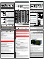
VL SUPPLY VOLTAGE OPTION
This is suitable for connection to a power
supply of 24Vac -15,+10% 48-62Hz or
24Vdc -15,+20%, 20W maximum.
Note. This MUST be fused using a T type fuse
(EN60127 time-lag type) rated at 4A.
!
Caution
Ensure that mains supplies are connected to the power supply terminals (100 to 230Vac only), the
fixed relay terminals or to relay or triac modules. Under no circumstances should mains supplies
be connected to any other terminals.
A protective Earth connection is required. ALWAYS ensure that the protective Earth is fitted
first and disconnected last.
INSTALLATION CATEGORY AND POLLUTION DEGREE
This unit has been designed to conform to BS EN61010 installation category II and
pollution degree 2. These are defined as follows:
Installation category II. The rated impulse voltage for equipment on nominal
230V ac mains is 2500V.
Pollution degree 2.
Normally, only non-conductive pollution occurs. However,
a temporary conductivity caused by condensation must be expected.
PERSONNEL
Installation MUST only be carried out by qualified personnel.
ENCLOSURE OF LIVE PARTS
To prevent hands or metal tools touching parts that may be electrically live, the unit
must be installed in an enclosure.
WIRING
It is important to connect the unit in accordance with the data on this sheet,
ensuring the protective Earth connection is ALWAYS fitted first and disconnected
last. Wiring MUST comply with all local wiring regulations, i.e. UK, the latest IEE
wiring regulations (BS7671), and USA, NEC Class 1 wiring methods. Only use
copper conductors for connections. Terminal tightening torque 0.4Nm (3.5lbin) max.
Caution
Do not connect AC supply to low voltage sensor input or low level inputs and outputs.
POWER ISOLATION
The installation must include a power isolating switch or circuit breaker. This
should be in close proximity (1 meter) to the unit, in easy reach of the operator and
marked as the disconnecting device for the unit.
OVERCURRENT PROTECTION
It is recommended that the power supply to the system is fused appropriately to
protect the cabling to the unit.
CONDUCTIVE POLLUTION
Electrically conductive pollution, i.e. carbon dust, MUST be excluded from the enclosure
in which the unit is installed. To secure a suitable atmosphere in conditions of
conductive pollution, fit an air filter to the air intake of the enclosure. Where
condensation is likely, include a thermostatically controlled heater in the enclosure.
OVER-TEMPERATURE PROTECTION
When designing a contol system it is essential to consider the consequences should
any part of the system fail. In temperature control applications the primary danger is
the heating will remain constantly on. This could spoil the product, but more
seriously damage the process machinery being controlled, or even cause a fire.
This may occur if the,
temperature sensor is detached from the process
thermocouple wiring has short circuited
unit fails with the heating output constantly on
external valve or contactor is sticking in the heating condition
unit setpoint is set to high
Where damage or injury can occur, it is recommended that a separate
over-temperature protection unit, and independant temperature sensor, to isolate the
heating circuit, is fitted.
Note. Alarm relays within the unit will not indicate all failure conditions.
INSTALLATION REQUIREMENTS FOR EMC
To comply with European EMC directive certain installation precautions are necessary:
General guidance. Refer to EMC Installation Guide, Part no. HA025464.
Relay outputs. It may be necessary to fit a suitable filter to suppress conducted
emissions. Filter requirements depend on the type of load.
Table top installation. If using a standard power socket, compliance to
commercial and light industrial emissions standard is usually required. To
comply with conducted emissions standard, a suitable mains filter must be
installed.
Installation Safety Requirements
Various symbols used on the instrument are described below:
!
Caution (refer to the
accompanying documents)
Protective earth
terminal
Functional
(ground) earth
MANUFACTURING ADDRESS
U.K. Worthing
Eurotherm Limited
Telephone: (+44 1903) 268500
Fax: (+44 1903) 265982
E-mail: [email protected]
Web: www.eurotherm.com
General
This unit is intended for Industrial Temperature and Process Control applications,
within the requirements of the European Directives on Safety and EMC.
Warning
The Safety and EMC protection provided can be seriously impaired, if the unit is not used in
the manner specified. The installer MUST ensure the Safety and EMC of the installation.
UNPACKING AND STORAGE
If on receipt, the packaging or unit are damaged, do NOT install, but contact the
supplier. If being stored before use, protect from humitity and dust in an ambient
temperature range of -30ºC to +75ºC.
Caution: Electrostatic discharge
Always observe all electrostatic precautions, before handling the unit.
SERVICE AND REPAIR
The unit has no servicable parts. Contact the supplier for repair.
CLEANING
Use Isolpropyl Alcohol to clean label. Labels will become illegible if water or water
based products are used. Use a mild soap solution to clean other exterior surfaces.
© Copyright Eurotherm Limited™ 2013
All rights are strictly reserved. No part of this document may be reproduced, modified, or
transmitted in any form by any means, nor may it be stored in a retrieval system other than for
the purpose to act as an aid in operating the equipment to which the document relates, without
the prior written permission of Eurotherm Limited.
Eurotherm Limited pursues a policy of continuous development and product improvement. The
specification in this document may therefore change without notice. The information in this
document is given in good faith, but is intended for guidance only. Eurotherm Limited will
accept no responsibility for any loses arising from errors in this document.
Power Supply
Note. Labels may differ between communication protocol variants.
POWER SUPPLY SPECIFICATION
VH SUPPLY VOLTAGE OPTION
This is suitable for connection to a power
supply of between 100 and 230Vac ±15%,
48 to 62 Hz, 20W maximum.
Note. This MUST be fused using a T type fuse
(EN60127 time-lag type) rated at 1A.
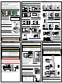
Digital I/O Terminals
The eight digital I/O connections provided can be individually configured as,
Input. Inputs are Logic (-1 to 35Vdc) or Contact Closure, and can be
configured for Manual, Remote, Run, Hold, Reset, etc,
Output. Outputs are open collector requiring an external power supply, and can
be configured as event Alarms, Time proportioning or valve position outputs.
Note. These terminals are NOT isolated from the Instrument ground.
DIGITAL INPUTS
Common
Logic Inputs
See Note 1, & 2
Common
Contact
Closure Inputs
See Note 1
See Note 3
Notes Digital Inputs
1 Logic Inputs or Contact Closure can be
wired in any combination.
2 Logic Inputs can accept drive signals
from a voltage source
Voltage Drive Signal Limits
<2V Active (1) -1V
>4V Inactive (0) +35V
3 D8 supports Digital Inputs Only.
Thyristor
Unit
Thyristor
Unit
SSR
SSR
Relay
Relay
Relay
External
PSU
Notes Digital Outputs
1 Relay, Thyristor or Solid State Relay
(SSR) Drive can be wired in any
combination.
2 Digital Outputs support 10 to 35Vdc
External Power Supply Unit (PSU)
3 Each output is current limited to 40mA.
See Note 2
I/O Expander Terminals
DATA TRANSFER
The primary use of the I/O Expander terminals (E1
and E2) is to connect an I/O Expander Module
(Model No 2000IO). This adds a further 20 digital
inputs and 20 digital outputs to this instrument.
Data transfer is performed serially via a two wire
interface from instrument to expander.
DIGITAL INPUT
These terminals can only be used as a secondary
digital input if the I/O Expander is not fitted. If
used in this way simply connect a 2K2, ¼W
limiting resistor in series with the input.
To
I/O Expander
Module
2K2
Limits
-1V, +35V
COMMUNICATIONS
SEE COMMUNICATIONS -
DEVICENET™, MODBUS/TCP, MODBUS
AND EI-BISYNCH, AND PROFIBUS™
Process Variable (PV) Input Terminals
The fixed Process Variable (PV) input terminals can be configured for Thermocouple,
PRT (Pt100), Pyrometer, Voltage (e.g. 0-10Vdc) or Milliamp (e.g. 4-20mA) and
vacuum - log10 signals. These sensors are used to provide inputs to Control Loop 1.
Note. The terminals are isolated from the Digital I/O. If using shielded cables, only ground one
end to avoid ground loop currents.
Voltage
(V)
Current
(mA)
See Note 4
+
-
2.49
ΩΩ
ΩΩ
Ω
mA
+
-
V
Milli-volts
(mV)
+
-
mV
See Note 5
Notes
1 Use appropriate compensating cable when configuring and extending a Thermocouple input.
2 Operating range between 0V to 10V or 0V to 2V.
3 Operating range up to 80mV.
4 Operating range between 0 to 20mA or 4 to 20mA.
5 A link MUST be fitted between V+ and V- if using a 2-wire PRT. The resistance of each wire
in a 3-wire PRT must be the same.
6 Do NOT run power and signal cables together.
2-, 3-wire Platinum
Resistance Thermometer
(PRT)
Thermocouple or
Pyrometer
See Note 1
+
-
See Note 3See Note 2
MODULES
SEE PLUG-IN I/O MODULES
Note.
Module position 2 is for future expansion.
24Vac
(-15,+10%)
or 24Vdc
(-15,+20%)
100 to
230Vac
Relay Terminals
These terminals can be configured as a control
output, an alarm, or event output. A single
changeover relay is provided as standard.
Notes
1 Connect the Power Supply last to avoid
electrical damage.
2 Use copper conductors only.
3 Do NOT run power and signal cables
together.
Common
Normally
Open
(NO)
Normally
Closed
(NC)
Relay Rating
Max - 264Vac, 2A
Min - 1V, 1mA
Analogue Input Terminals
The Analogue Input Terminals (BA and BB) accept volts, e.g. 0-10Vdc, or Milliamp,
e.g. 4-20mA, signals. The signals can be used for remote setpoint input, remote
setpoint trim or as a high level PV input to a control loop and can be characterised
to match a particular curve from a transmitter.
Note. The terminals are NOT isolated from the Digital I/O and do NOT support direct input
from a Thermocouple.
Notes
1 To earth screened cables, connect the screen at supply end.
2 To earth screened cables, connect the screen to terminal BC.
Isolated Voltage
(0V - 10V)
Non-Isolated Current
(0 - 20mA) (4 - 20mA)
See Note 1
+
-
100
ΩΩ
ΩΩ
Ω
Isolated Current
(0 - 20mA) (4 - 20mA)
+
-
See Note 2
Non-Isolated Voltage
(0V - 10V)
See Note 1
+
-
+
-
See Note 2
100
ΩΩ
ΩΩ
Ω
DIGITAL OUTPUTS
+
-
Note
Wiring Specifics
. All electrical connections made to screw terminals protected by a clear plastic
hinged cover, used to prevent accidental contact with live wires. The terminals accept wire sizes
from 0.5 to 1.5mm2 (16 to 22 AWG) and should be tightened to a torque of 0.4Nm
(3.5lbin). If
using crimp connectors, the correct size is AMP, part number 349262-1.
High Voltage Supply Low Voltage Supply
Legend Supply Legend Supply
L Line 24 24V ac/dc
N Neutral 24 24V ac/dc
Earth Earth
-+
2604/2704 HIGH PERFORMANCE
CONTROLLER/PROGRAMMER
INSTALLATION AND WIRING INSTRUCTIONS
These instruments are modular, fully configurable, high accuracy, high stability
temperature and process controllers, available in a single, dual or three loop format.
Each unit is supplied as a specific hardware configuration, e.g. there are five ‘slots’
that contain specific plug in modules, identified by a hardware code printed on the
label on the side of the controller at time of ordering. The unit can also be supplied
with pre-configured software for some simple applications according to an optional
Configuration Code, or configured via the front panel or iTools Engineering Studio.
The 2604 has a dual 7-segment display of process value and setpoint with a LCD
panel for display of information and user defined messages. The user interface is menu
driven via the display and seven front panel keys.
Part No. HA029465 (CN29750) Issue 3 Mar 13
The 2704 has a 120 x 160 pixel electroluminescent display of all process value and
setpoint information and user defined messages. The user interface is menu driven via
the display and seven front panel keys.
FEATURES INCLUDE:
Advanced ramp/dwell programmer with storage of up to 50 programs for the 2604
and 60 programs for the 2704.
Application specific controllers (including Handbook), i.e. Vacuum Furnace,
Carbon Potential, Humidity, Boiler (TDS) and Melt Pressure.
A wide variety of configurable inputs, including thermocouples, Pt100 resistance
thermometers (PRT) and high level process inputs.
Loop configuration as PID, On/Off or motorised valve position, with control of
strategies including single, cascade, override and ratio control.
PID control outputs can be relay, logic, triac or dc with motorised valve position
outputs being relay triac or logic.
Simplified commissioning and optimised process available via Auto Tuning and
PID gain scheduling.
Note. Refer to the Engineering Handbook for Operation and Configuration details, available on
the enclosed CD (Part No. LA029175) or via the website.
27042604
WARNING
This instrument is fitted with a back up battery which should be changed at regular
intervals.
It is important to maintain a record of instrument configuration or, preferably, a
clone file which can be re-loaded after a battery change or any other maintenance.
The battery is not serviceable, contact your local service centre to make suitable
arrangements. For further information see the User Manuals at www.eurotherm.co.uk

DIRECT PANEL MOUNTING
1. Check that the mounting panel is not
thicker than 15mm (0.6 inches)
(typically for wood or plastic) and not
thinner than 2mm (0.08”) (for steel).
2. In the mounting panel, cut an aperture
92mm x 92mm (+ .8mm).
Note. Ensure the Unit is not mounted close to any
device that is likely to produce enough heat to
affect the performance.
3. Insert the Unit through the panel cut out.
4. Spring the upper and lower panel retaining
clips into place. Secure the unit by holding
it level and pushing both retaining clips
forward.
Once fitted this unit is IP65 rated.
Note. If removing the retaining clips, unhook the side
using fingers or a screwdriver, and extract
(slide) the unit from the mounting panel.
REMOVING THE CONTROLLER
The controller can be removed from the sleeve by easing the latching ears on either
side of the sleeve outwards and pulling the controller forward. When fitting the
controller back into the sleeve, ensure the latching ears click into place.
Warning
For safety reasons and to prevent premature wear on the connectors the Power to the
Unit MUST be isolated before removing the Controller.
WIRING
Communications - DeviceNet™
Protocol is DeviceNet™ interface requiring each node to have a
unique address on the DeviceNet™ network and must be set to the
same Baud rate.
Note. Refer to DeviceNet
™
Communications Handbook,
Part No. HA027506ENG.
Communications - Profibus™
Protocol is Profibus DP requiring each node to have a unique address on
the Profibus network and must be set to the same Baud rate.
Note. Refer to Profibus
™
Communications Handbook, Part No. HA026290.
CAN Chip
Legend Label Colour Description
HA V+ Red DeviceNet™ network power positive terminal.
Note. If the DeviceNet™ network does not supply the power, connect to the
positive terminal of an external 11-25 Vdc power supply.
HB CAN_H White DeviceNet™ CAN_H data bus terminal.
HC DRAIN None Shield/Drain wire connection. To prevent
ground loops, the DeviceNet™ network
should be grounded in only one location.
HD CAN_L Blue DeviceNet™ CAN_L data bus terminal.
HE V- Black DeviceNet™ network power negative
terminal.
Note. If the DeviceNet™ network does not supply the power, connect to the
negative terminal of an external 11-25 Vdc power supply.
HF - Connect to instrument earth.
Caution
Power Taps are recommended if connecting a DC power supply to the DeviceNet
trunk line. To connect multiple Power supplies, fit a Schottky diode to the V+ of each
Power Supply unit. Connect 2 fuses or Circuit Breakers to protect the Bus from
excessive current, that may cause damage to the cables and connectors. Connect the
Instrument Earth terminal, HF, to the main Power supply earth terminal.
WIRING
The Unit
Before installing the unit check the packaging contains the Unit, mounting
components, and a CD, and the Hardware code and Configuration code to ensure
that it is suitable for the process specified.
TO MOUNT THE UNIT
The Unit is supplied as two parts, the controller and the sleeve, but is intended to
be mounted together through a cut out in the front panel of an electrical control
cabinet. It is held in position using the panel retaining clips supplied.
The Unit can be mounted vertically or on a sloping panel of maximum thickness
15mm (0.6 inches). Adequate access space must be available at the rear of the
instrument panel for wiring and servicing purposes.
Note. Once mounted, the Controller may be removed from the sleeve at any time.
Communications - Modbus
Protocol is Modbus RTU, EIA232, EIA485 3-wire or 5-wire.
Note. Refer to 2000 Series Communications Manual, Part No. HA026230.
The Modbus network connection is via the HA to HF and JA to JF
terminal connections. Units MUST be connected in a daisy-chain
method using twisted pair cable.
Note. The Screen from each cable should be connected through and grounded at
one point only.
Plug-in I/O Modules
Use 4-terminal I/O modules at Module 1, 3, 4, 5, and 6 only, except where stated.
Note. Check the order code on the side of the unit, to learn what modules are fitted,
and use ‘View Config’ level to inspect each Module position. Any changes to the
Modules Position should be recorded on the side of the unit.
OUTPUT TYPES
Legend EIA232 EIA485 3-wire EIA485 5-wire
HA (JA) N/A N/A N/A
HB (JB) N/A N/A Rx+
HC (JC) N/A N/A Rx-
HD (JD) Com Com Com
HE (JE) Rx A Tx+
HF (JF) Tx B Tx-
Note. Alternatively, use the JA to JF terminals.
A
B
C
See Note
B
Note. Always allow sufficient
clearance for ventilation
and connections.
10mm
(0.4”)
38mm
(1.5”)
Panel cutout
92mm x 92mm
(+ .8mm)
(3.62” x 3.62”
(+0.03”))
See Note
See Note
EIA232
EIA485 5-WIRE
TERMINATION RESISTOR
A 121Ω Termination Resistor must not be fitted as any part of a
master or slave if already internally installed.
View A
EIA485 3-WIRE
View A
View A
View A
Legend Signal 9 Pin D Type Description
HA N/A
HB Shield 1 Shield/Drain wire connection.
HC VP (+5V) 6 5V supply
HD Rx/Tx (+ve) 3 Profibus network power positive terminal.
HE Rx/Tx (-ve) 8 Profibus network power negative terminal.
HF Dig Grnd 5 Digital Ground.
Use standard ProfiBus cables, ‘Line A’
and ‘Line B’, with special 9 pin D Type
male connector headers, allowing one
or two cables to be fitted. A termination
load is built in with an ON/OFF switch,
set to ON at the two ends of the line.
When using 9 pin D Type connections
a further assembly is required.
TERMINATION RESISTOR
The Profibus specification states that the Termination Resistor must be
fitted to the last nodes in the line.
220
ΩΩ
ΩΩ
Ω
390
ΩΩ
ΩΩ
Ω
390
ΩΩ
ΩΩ
Ω
2-pin (R2) or Dual Relay (RR)
Voltage
Supply
Contactor
Relay Panel
lamp, etc.
Contactor
Relay Panel
lamp, etc.
Voltage
Supply
Contactor
Relay Panel
lamp, etc.
Note. Both Relays support 264Vac , 2A max, 12V, 10mA min.
Communications - Modbus/TCP
Protocol is Modbus/TCP, 10 Base T on an Ethernet network.
Note. Supported by the 2704 Unit only.
This requires an additional connector,
Part no. SUB27/EA. It connects to the HA
to HF terminals and allows communications
via standard CAT5 cables directly to a
Computer or Ethernet Switching unit/Hub.
Note. A cross-over cable MUST be used if
connecting directly to a Computer operating
as a Network master.
RJ45 Pin Colour Signal
8 Brown N/A
7 Brown/White N/A
6 Green Rx-
5 Blue/White N/A
4 Blue N/A
3 Green/White Rx+
2 Orange Tx-
1 Orange/White Tx+
Plug shroud to Cable screen
Pin 8
Pin 1
O/P 1
+
-
DC Control (D4) or
DC Re-Transmission (D6)
To Actuator
or Controllers
0 - 20mA or
0 - 10Vdc
Dual DC Output (DO) High Resolution DC Output (HR)
+
-
O/P 2
+
-
4 - 20mA 20V - 30V
Notes Dual DC Output
1 Supports 4 - 20mA or 24Vdc power supply.
2 Fit in Module positions, 1, 4, and 5 only.
O/P 1
+
-
O/P 2
+
-
20V - 30V
Notes High Resolution Dual DC Output
1 Supports one 15-bit 4 - 20mA and one
24Vdc power supply per channel.
2 Fit in Module positions, 1, 4, and 5 only.
4 - 20mA
Triac (T2) and Dual Triac (TT)
Voltage
Supply
SSR or
Thyristor
Unit
Lower
Raise
Notes Triac and Dual Triac
1 The combined current rating for the Dual
Triacs must not exceed 0.7A, 30 - 264Vac.
2 Dual Relay modules can be configured to
offer the same control as the Dual Triac.
First Triac
Second Triac
2-, 3-wire PRTThermocouple
or Pyrometer
+
-
Milli-volts (mV)
(up to 100mV)
+
-
mV
Voltage (V)
(0V to 10V or
0V to 2V)
+
-
V
Current (mA)
(0mA to 20mA or
4mA to 20mA)
+
-
2.49
ΩΩ
ΩΩ
Ω
mA
TERMINATION RESISTOR
A 220Ω Termination Resistor MUST be fitted across the Receiver
signals (Rx+ and Rx-) at each end of a maximum 32 communicating
instruments.
Note. Wire to Actuators for DC Control, and to
Controllers for DC Re-Transmission.
Isolated Single Logic (LO)
SSR or
Thyristor
Unit
-
+
Common
+
-
Isolated Triple Logic (TP)
SSR or
Thyristor
Unit
-
O/P A
Common
+
O/P B
+
O/P C
+
Note. Isolated Triple Logic Output supports
18Vdc, @ 8mA max, per channel.
+
-
Notes EIA485
1 Use twisted pair cable throughout.
2 An EIA232 to EIA485 converter is required when connecting directly to a Computer.
220
ΩΩ
ΩΩ
Ω
Note. Isolated Single Logic Output supports
18Vdc, @ 24mA max, per channel.
Start
End
Node
Last End Node
To
Converter
View A
220
ΩΩ
ΩΩ
Ω
To
Converter
To
Computer
Start
End
Node
View A
Environmental Requirements Minimum Maximum
Temperature 0ºC 50ºC
Humidity (Relative - RH) 5% RH 95% RH
Altitude 2000m
Note. 100
ΩΩ
ΩΩ
Ω
to 15K
ΩΩ
ΩΩ
Ω
range.
Wiper
+0.5V
0 V
Zirconia Probe Dual
PV Input (DP)
+
-
Voltage
Supply
+
-
+
-
Voltage
Supply
+
-
V
Note. <5V Off, >10.8V On.
Limits: -3V, +30V.
I/P A
Common
I/P B
I/P C
I/P A
Common
I/P B
I/P C
Note. <100
ΩΩ
ΩΩ
Ω
On,
>28K
Ω Ω
Ω Ω
Ω
V Off.
Triple Logic Input (TL) Triple Contact Input (TK) Potentiometer Input (VU)
Dual PV Input (DP)
(Current source)
2.49
ΩΩ
ΩΩ
Ω
100
ΩΩ
ΩΩ
Ω
+
-
+
-
0 - 2V
0 - 20mA
4-wire PRT (PH or PL)
Note. Wire Voltage Supply
to any Input.
Note. Common connections to
D, must be returned to
D separately.
Notes
1 If runs exceed 30 metres use screened cables.
2 Ensure the resistance of each wire is the same.
3 PH version uses 100
ΩΩ
ΩΩ
Ω
, PL version uses 25.5
ΩΩ
ΩΩ
Ω
.
Last End Node
View A
View A
121
ΩΩ
ΩΩ
Ω
Last End Node
Last End Node
View A
9 Pin D Type
(Female)
Spacer
Unit
(HA to HF)
SUB26 or SUB27/PROF9PIND
See Note
POWER
Transducer Power Supply Output (G3 or G5)
-
+
B
C
A
D
To Fixed or
PV Input
Module
Notes
1 Fit an external calibration resistor if not already installed.
2 Use screened cable to reduce interference for Strain
Gauge power supply connections
3 Uses 5 or 10Vdc to power Strain Gauge Transducer
4 Uses Shunt Contact for automatic calibration.
See Note 1
24V Transmitter Output (MS)
+
Trans-
mitter
-
Note. 20mA to external
transmitter.
Change Over Relay (R4)
INPUT TYPES
These support both PV (PV), Module positions 3 and 6 only, and Analogue Input (AM)
Modules, any position except Module position 5.
Note. If using 2-wire PRT, fit link between C and D.
These support PV Input (PV) Modules, restricted to Module positions 3 and 6.
These support Digital and Potentiometer Input Modules fitted in any position.
Probe tip
Driver tip
Earth
Sensor tip
2 Electrode Probe 3 Electrode Probe
Boiler Earth
Earth
Sensor tip
Boiler Earth
Current Electrode 1
Voltage Electrode 1
Zirconia Probe
2 PV Input Modules (PV)
TDS MODULE (2704 ONLY)
Probe
Probe
ProbeProbe
4 Electrode Probe
Voltage Electrode 2
Current Electrode 2
Note. Adhere to suppliers
recommendations for grounding
and screen connections.
Dimension Measurement
A 96 mm (3.78 Inches)
B 96 mm (3.78 Inches)
C 150 mm (5.91 Inches)
-
 1
1
-
 2
2


Euroterm 2604 Operating instructions
- Category
- Networking
- Type
- Operating instructions
- This manual is also suitable for
Ask a question and I''ll find the answer in the document
Finding information in a document is now easier with AI