Page is loading ...

NAVpilot-300
OPERATOR'S MANUAL
www.furuno.com
Model
AUTOPILOT

7KHSDSHUXVHGLQWKLVPDQXDO
LVHOHPHQWDOFKORULQHIUHH
࣭)85812$XWKRUL]HG'LVWULEXWRU'HDOHU
$VKLKDUDFKR
1LVKLQRPL\D-$3$1
$ 2&7
3ULQWHGLQ-DSDQ
$OOULJKWVUHVHUYHG
% $35
3XE1R 20(%
<26+ 1$9SLORW

i
IMPORTANT NOTICES
General
• This manual has been authored with simplified grammar, to meet the needs of international users.
• The operator of this equipment must read and follow the descriptions in this manual. Wrong oper-
ation or maintenance can cancel the warranty or cause injury.
• Do not copy any part of this manual without written permission from FURUNO.
• If this manual is lost or worn, contact your dealer about replacement.
• The contents of this manual and equipment specifications can change without notice.
• The example screens (or illustrations) shown in this manual can be different from the screens you
see on your display. The screens you see depend on your system configuration and equipment
settings.
• Save this manual for future reference.
• Any modification of the equipment (including software) by persons not authorized by FURUNO will
cancel the warranty.
• The following concern acts as our importer in Europe, as defined in DECISION No 768/2008/EC.
- Name: FURUNO EUROPE B.V.
- Address: Ridderhaven 19B, 2984 BT Ridderkerk, The Netherlands
• All brand and product names are trademarks, registered trademarks or service marks of their re-
spective holders.
• The Bluetooth
®
word mark and logos are registered trademarks owned by Bluetooth SIG, Inc.
How to discard this product
Discard this product according to local regulations for the disposal of industrial waste. For disposal
in the USA, see the homepage of the Electronics Industries Alliance (http://www.eiae.org/) for the
correct method of disposal.
How to discard a used battery
Some FURUNO products have a battery(ies). To see if your product has a battery, see the chapter
on Maintenance. Follow the instructions below if a battery is used. Tape the + and - terminals of bat-
tery before disposal to prevent fire, heat generation caused by short circuit.
In the European Union
The crossed-out trash can symbol indicates that all types of batter-
ies must not be discarded in standard trash, or at a trash site. Take
the used batteries to a battery collection site according to your na-
tional legislation and the Batteries Directive 2006/66/EU.
In the USA
The Mobius loop symbol (three chasing arrows) indicates that Ni-
Cd and lead-acid rechargeable batteries must be recycled. Take
the used batteries to a battery collection site according to local
laws.
In the other countries
There are no international standards for the battery recycle symbol. The number of symbols can in-
crease when the other countries make their own recycle symbols in the future.
7305A-RM1017
IC Approved Bluetooth®
IC Approved Bluetooth®
Cd
Ni-Cd Pb

ii
SAFETY INSTRUCTIONS
WARNING
Indicates a condition that can cause death or serious injury if
not avoided.
CAUTION
Indicates a condition that can cause minor or moderate injury
if not avoided.
Warning, Caution
Mandatory Action
Prohibitive Action
Please read these safety instructions before you operate the equipment.
WARNING
WARNING
Use the correct fuse.
Use of a wrong fuse can cause fire or
damage the equipment.
Turn off the power immediately if
water leaks into the equipment or the
equipment is emitting smoke or fire.
Continued use of the equipment can
cause fire or electrical shock.
Do not disassemble or modify
the equipment.
Fire or electrical shock can result if
the equipment is modified.
Do not set the course changing
speed too high.
The boat will be turned too sharply at
the course change, which could create
a very dangerous situation.
Observe the following cautions when
using the autopilot:
- Maintain a vigilant watch
- Watch for drifting of vessel
Do not use the autopilot in the
following situations:
- Own ship speed is over 40 knots
- When navigating narrow channels
- When entering/leaving the harbor
- When navigating areas with heavy
traffic
- When navigating areas with a narrow
view, affected by fog/mist/rain
- When moored
Do not use the SIMULATION mode on
the boat.
The rudder may move suddenly. This is
a special-purpose mode for technicians.
Do not use the ORBIT turn in rough
seas.
Because the boat turns a 360° circle
around the waypoint, a large wave or
strong wind can cause the boat to capsize.
For the figure-eight mode, confirm
that no object is in the general vicinity
of the waypoint.
The distance from the waypoint to the
turning point depends on boat's speed.

SAFETY INSTRUCTIONS
iii
CAUTIONCAUTION
Keep the following points in mind
when using Fantum Feedback
TM
.
In case of power failure, turn off the
autopilot or manually steer the vessel.
Leaving the equipment in the AUTO or
NAV mode during power failure will
cause wear on the rudder mechanism.
Do not apply force excessive force or
shock to the LCD panel.
Force or shock can damaged the LCD or
cause equipment failure
CAUTIONCAUTION
Only use the specified battery.
When replacing the battery, make
sure the polarity is correct.
Incorrect placement of the battery can
cause the battery to explode or damage
the equipment.
The autopilot cannot detect the rudder
position when using Fantum
Feedback
TM
. Therefore, over-steering
after reaching rudder limit can occur. If
over-steering continues, the drive unit
may malfunction, preventing automatic
steering. To prevent over-steering, keep
the following points in mind.
- Use the autopilot within the speed at
which the autopilot can control the
vessel. Pay particular attention when
keeping the stern facing windward (or
into the current) in the SABIKI mode.
- Always check the rudder position to
stop the rudder with the autopilot before
reaching the rudder limit.
- When the rudder reaches rudder limit,
the drive unit is temporarily disabled and
the autopilot cannot move the rudder. If
this occurs, the deviation alarm (see
section 3.5) sounds regardless of the
setting value. In this case, switch to the
STBY mode and turn the helm to move
the rudder.
Name: Caution Label (Small)
Type: 64-034-2002
Code No.: 100-416-400-10
Caution Label(s)
Caution label(s) is(are) attached to the
equipment. Do not remove the label(s).
If a label is missing or damaged, contact a
FURUNO agent or dealer about replacement.
About the TFT LCD
The TFT LCD is constructed using the latest LCD techniques, and displays
99.99% of its pixels. The remaining 0.01% of the pixels may drop out or
blink, however this is not an indication of malfunction.
Do not use high-pressure cleaners to
clean this equipment.
This equipment has the waterproof
rating outlined in the specifications, at
the back of this manual. However, the
use of high-pressure cleaning equipment
can cause water ingress, resulting in
damage to, or failure of, the equipment.

iv
TABLE OF CONTENTS
FOREWORD ...................................................................................................................vi
SYSTEM CONFIGURATION .........................................................................................vii
1. INTRODUCTION ....................................................................................................1-1
1.1 Controls Overview...................................................................................................... 1-1
1.2 How to Turn Power On, Off........................................................................................ 1-3
1.3 How to Adjust the Brilliance and Panel Dimmer......................................................... 1-4
1.4 How to Change the Display Color .............................................................................. 1-5
1.5 Steering Modes Overview .......................................................................................... 1-6
1.5.1 Graphic area .................................................................................................. 1-6
1.5.2 Data box area................................................................................................. 1-9
1.6 Menu Operations Overview...................................................................................... 1-10
2. STEERING MODES ...............................................................................................2-1
2.1 Standby (STBY) Mode ............................................................................................... 2-1
2.2 AUTO mode ............................................................................................................... 2-2
2.2.1 How to activate AUTO mode.......................................................................... 2-2
2.2.2 ADVANCED AUTO mode .............................................................................. 2-4
2.3 NAV Mode.................................................................................................................. 2-5
2.3.1 How to activate NAV mode ............................................................................ 2-5
2.3.2 Sailing method for NAV mode........................................................................ 2-7
2.3.3 Waypoint switching method ........................................................................... 2-7
2.3.4 How to set the steering behavior of your boat after you arrive at a waypoint 2-8
2.4 TURN Mode ............................................................................................................... 2-8
2.4.1 How to select a turn and start the turn ........................................................... 2-8
2.4.2 How to set the angle for turns ...................................................................... 2-10
2.5 FishHunter
™
Mode................................................................................................... 2-11
2.5.1 How to select a FishHunter
™
turn and start the turn.................................... 2-11
2.5.2 Types of turns available with FishHunter
™
.................................................. 2-12
2.5.3 How to set up the FishHunter
™
parameters ................................................ 2-16
2.6 SABIKI
™
Mode......................................................................................................... 2-17
2.6.1 How to use the SABIKI
™
mode.................................................................... 2-18
2.6.2 How to adjust the response for SABIKI
™
mode........................................... 2-19
2.7 DODGE and NFU Modes......................................................................................... 2-20
2.7.1 How to use DODGE mode ........................................................................... 2-20
2.7.2 How to use NFU mode................................................................................. 2-20
2.8 OVRD mode (only for EVC system)......................................................................... 2-21
2.8.1 OVRD mode activation in STBY mode ........................................................ 2-21
2.8.2 OVRD mode activation in the AUTO or NAV mode ..................................... 2-21
2.9 Safe Helm Mode ...................................................................................................... 2-22
2.10 Power Assist Mode .................................................................................................. 2-24
3. ALERTS .................................................................................................................3-1
3.1 How to Show the Alert Menu...................................................................................... 3-2
3.2 How to Set the Watch Alert ........................................................................................ 3-2
3.3 How to Set the Deviation Alert ................................................................................... 3-2
3.4 How to View the Alert Messages ............................................................................... 3-3
3.5 How to Show the Alert Log......................................................................................... 3-3
4. HOW TO CUSTOMIZE YOUR NAVPILOT ............................................................4-1
4.1 How to Setup the Parameters .................................................................................... 4-1
4.1.1 Automatic parameter setup ............................................................................ 4-1

TABLE OF CONTENTS
v
4.1.2 Manual parameter setup ................................................................................4-2
4.1.3 Speed calculation ...........................................................................................4-4
4.2 Rudder Drive Level (For Fantum Feedback
™
) ...........................................................4-4
4.3 Nav Data Source ........................................................................................................4-5
4.4 System Setup Menu ...................................................................................................4-5
5. GESTURE CONTROLLER GC-001 ......................................................................5-1
5.1 Gesture Controller GC-001 Overview.........................................................................5-1
5.2 How to Turn the Power On/Off ...................................................................................5-1
5.3 Display Overview........................................................................................................5-2
5.4 GC-001 Menu Overview.............................................................................................5-3
5.5 GC-001 Alerts.............................................................................................................5-5
5.5.1 Alert priority ....................................................................................................5-5
5.5.2 Alert list...........................................................................................................5-5
5.6 How to Adjust the Settings for Your GC-001..............................................................5-8
5.6.1 How to lock/unlock the keys ...........................................................................5-8
5.6.2 How to change the buzzer and vibration settings...........................................5-8
5.6.3 How to enable/disable the gesture-to-turn feature .........................................5-9
5.6.4 How to turn the screen’s backlight on/off .......................................................5-9
5.6.5 How to set the sleep timer..............................................................................5-9
5.6.6 How to use the [AUTO OFF] feature ............................................................5-10
5.7 How to Use the Gesture-To-Turn Feature................................................................5-10
5.8 How to Connect (Pair) the GC-001 with Your NAVpilot-300 ....................................5-11
5.9 GC-001 Operations With NAVpilot-300....................................................................5-13
5.9.1 Standby (STBY) mode .................................................................................5-13
5.9.2 Autopilot (AUTO) mode ................................................................................5-14
5.9.3 Navigation (NAV) mode................................................................................5-15
5.9.4 TURN and FISHHUNTER
™
modes..............................................................5-16
5.9.5 SABIKI
™
mode .............................................................................................5-17
5.10 Diagnostics Menu .....................................................................................................5-18
6. MAINTENANCE, TROUBLESHOOTING ..............................................................6-1
6.1 Preventive Maintenance .............................................................................................6-1
6.2 Replacement of Fuse .................................................................................................6-2
6.3 Troubleshooting..........................................................................................................6-2
6.4 Diagnostics.................................................................................................................6-4
6.4.1 Diagnostic menu.............................................................................................6-4
6.4.2 Processor unit test..........................................................................................6-5
6.4.3 Control unit test ..............................................................................................6-6
6.4.4 Keyboard test .................................................................................................6-7
6.4.5 Screen test .....................................................................................................6-7
6.4.6 Rudder test.....................................................................................................6-8
6.4.7 Helm sensor test ..........................................................................................6-11
6.5 System Data.............................................................................................................6-12
6.6 Messages .................................................................................................................6-13
6.6.1 Message pop-up display ..............................................................................6-13
6.6.2 Message menu.............................................................................................6-13
6.6.3 Message description ....................................................................................6-14
6.7 How to View the Sensors in Use ..............................................................................6-16
APPENDIX 1 MENU TREE .......................................................................................AP-1
SPECIFICATIONS ..................................................................................................... SP-1
INDEX ......................................................................................................................... IN-1

vi
FOREWORD
A Word to the Owner of the NAVpilot-300
Features
Program numbers
“xx” denotes minor version changes.
CE Declaration
With regards to CE declarations, please refer to our website (www.furuno.com) for further infor-
mation about RoHS conformity declarations.
Congratulations on your choice of the NAVpilot-300. We are confident you will see why the FURUNO
name has become synonymous with quality and reliability.
Since 1948, FURUNO Electric Company has enjoyed an enviable reputation for innovative and de-
pendable marine electronics equipment. This dedication to excellence is furthered by our extensive
global network of agents and dealers.
Your equipment is designed and constructed to meet the rigorous demands of the marine environ-
ment. However, no machine can perform its intended function unless properly operated and main-
tained. Please carefully read and follow the operation and maintenance procedures set forth in this
manual.
Thank you for considering and purchasing FURUNO.
We would appreciate feedback from you, the end-user, about whether we are achieving our purpos-
es.
The NAVpilot-300 is comprised of a processor unit, display unit and a remote controller. This system
is design for use in 25 ft or larger boats with inboard, outboard, in/outboard engines or DBW engines*.
The main features of the NAVpilot-300 are:
• Remote operation made possible with the standard supply GC-001 Gesture Controller.
• “Adaptive” technology which allows your NAVpilot to continue improving your boat’s steering on
every voyage.
• Versatile, high-resolution color LCDs provide a variety of user-defined display configurations.
• Auto set-up and self-learning for boat speed and course.
• One-touch access to all operation modes.
• “FishHunter
™
” guides your boat in circle, orbit, spiral, figure-eight or zigzag maneuvers around fish
schools or other targets.
• Compatible with NavNet TZtouch and NavNet TZtouch2 plotters.
• Network up to 3 NAVpilot-300 systems.
*: DBW (Drive By Wire) systems compatible with the NAVpilot-300 are as follows:
• VOLVO PENTA IPS
• YAMAHA Helm Master
• YANMAR VC10
• SEASTAR SOLUTIONS OPTIMUS (The software version of the connected Main PCM (Pump
Control Module) must be “Rev. T” or later.)
System Program no. System Program no. System Program no.
GC-001 FAP-3012 FAP-3011
MAIN 6454030.xx MAIN 6454026.xx MAIN 6454024.xx
BOOT 6454029.xx BOOT 6454027.xx BOOT 6454025.xx
BLE 6454031.xx BLE 6454032.xx

vii
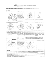
SYSTEM CONFIGURATION
12/24 VDC
Reversible Pump
Junction Box
Linear Sensor
Safe Helm System
Event Switch
Rudder Reference Unit
FAP-6112
Gesture Controller
GC-001 (Max. 3 Units)
Processor Unit
FAP-3012
Junction Box
*
1
: Termination resistors must be installed at both ends of the backbone.
*
2
: EVC systems compatible with the NAVpilot are as follows:
Termination
resistor*
1
Control Unit
FAP-3011 (Max. 3 Units)
15 VDC
: Standard supply
: Option or local supply
Junction Box
FI-5002
Termination
resistor*
1
Integrated Heading Sensor
PG-700
CAN bus (NMEA2000)
Device
EVC System
*
2
EVC System Remarks
VOLVO PENTA IPS
YAMAHA Helm Master
YANMAR VC10
SEASTAR SOLUTIONS OPTIMUS
Requires VOLVO IPS gateway (available as an optional extra).
Requires YAMAHA HM gateway (available as an optional extra).
-
The software version of the Main PCM (Pump Control Module)
must be “Rev. T” or later.

SYSTEM CONFIGURATION
viii
This page is intentionally left blank.

1-1
1. INTRODUCTION
The NAVpilot-300 can be controlled either from the Control Unit (FAP-3011) or from
the Gesture Controller (GC-001). For details regarding the GC-001, see chapter 5.
1.1 Controls Overview
The keys beep when operated to inform you if the operation was successful, or if the
operation is not allowed. One beep indicates successful operation, two beeps indi-
cates an operational error.
You can turn the key beeps off or on to suit your needs. See section 4.4 for details.
The figure below shows the FAP-3011 control unit. For GC-001 controls, see
chapter 5.
The table below outlines the basic functions of the items highlighted in the figure
above. Detailed instructions on their use is described chapter 2.
Name Description
PORT 10 key Short press
:
• With Auto active: Change course by 10° to port.
• Open the selected setup menu.
Long press
:
• With Auto active: Start a 180° (factory default) turn to port.
• With NAV mode active: Switch to Dodge (port turn) mode
PORT 1 key Short press
:
• With Auto active: Change course by 1° to port.
• Increase the value for the selected setting.
• Move the selection cursor upwards in the menu.
• With the system in STBY: Switch between digital indications
and dial indications.
Long press
:
• With Auto active: Start a 90° (factory default) turn to port.
10
1

1. INTRODUCTION
1-2
Power/Brill key Short press:
• With the system turned off: Turn the system on.
• With the system turned on: Show the brilliance settings win-
dow.
• With the brilliance settings window open: Cycle thorough the
brilliance levels.
Long press
:
• Turn the system power off (three second countdown appears).
Auto Pilot key • Close all open windows and menus.
• Switch to STBY (standby) mode.
With no destination selected at the GPS navigator:
• Switch to AUTO mode.
With a destination selected at the GPS navigator:
• Open the mode ([NAV]/[AUTO]/[CANCEL]) selection window.
STBD 1 key Short press:
• With AUTO mode active: Change course by 1° to starboard.
• Decrease the value for the selected setting.
• Move the selection cursor downwards in the menu.
• With the system in STBY: Switch between digital indications
and dial indications.
Long press:
• With Auto active: Start a 90° (factory default) turn to starboard.
MENU key Short press
:
• Open the [TURN] menu.
• With the menu open: Go back one level in the menu.
Long press
:
• Open/close the main menu.
STBD 10 key Short press
:
• With AUTO mode active: Change course by 10° to starboard.
• Open the selected menu.
Long press
:
• With AUTO mode active: Start a 180° (factory default) turn to
starboard.
• With NAV mode active: Switch to Dodge (starboard turn)
mode
Name Description
STBY
1
10

1. INTRODUCTION
1-3
1.2 How to Turn Power On, Off
Note: When the Heading Sensor PG-500/PG-700 is connected, turn on the NAVpilot
and wait a few minutes before you leave port, or steer the boat manually. This allows
time for the PG-500/PG-700 heading data to stabilize.
Turning the power on
To turn the power on, press . The unit releases a “beep” to indicate when the
startup procedure begins.
The equipment shows
product information,
connects to the proces-
sor unit and begins the
startup test. The start up
test checks the ROM,
RAM and backup data
for the processor unit
and control unit. The
test also checks for the
presence of heading information from the heading sensor and rudder angle informa-
tion from the rudder reference unit. When all test results are indicated as "OK", the
Auto Pilot main screen appears.
If a problem occurs with any of the tested items, an error message, shown in the table
on the following page, appears. The test result is also indicated as "NG" (No Good).
Follow the information below to restore normal operation. If you cannot restore normal
operation, contact your dealer for information.
Priority Error message Meaning
High
n
p
Low
Communication error with the processor
unit.
Check connections.
Contact your local dealer if the problem re-
curs.
The Control Unit failed to connect to the Pro-
cessor Unit. Turn the system off and check
the connections between the units. Re-con-
nect any loose or disconnected cables. If
the problem recurs after restarting the sys-
tem, contact your local dealer.
Processor has failed the startup test.
Contact your local dealer.
The Processor Unit may be faulty. Contact
your local dealer and arrange for service.
Controller has failed the startup test.
Contact your dealer.
The Control Unit may be faulty. Contact
your local dealer and arrange for service.
Processor backup data is corrupt or lost.
Processor factory defaults will be restored.
Press any key to continue.
Backup data for the Processor Unit is not
usable. The system will restore factory de-
fault settings for the Processor Unit. Press a
key to start the process.
Controller backup data is corrupt or lost.
Controller factory defaults will be restored.
Press any key to continue.
Backup data for the Control Unit is not us-
able. The system will restore factory default
settings for the Control Unit. Press a key to
start the process.
Control unit and processor unit software
versions do not match.
Update software to latest version.
There is a difference in the software ver-
sions for the Processor and Control Units.
Contact your local dealer to update the soft-
ware of both units to the latest version.
COG
COG
Processor
:XX. XX
*1
/XX. XX
*2
Controller
:XX. XX
*1
/XX. XX
*2
Connecting to Processor Unit...
Startup screen Standby mode screen
*1
: Indicates the application version number.
*2
: Indicates the boot program version number.

1. INTRODUCTION
1-4
You can acknowledge and hide any of these errors. To acknowledge and hide an error
message, press any key on the Control Unit. If there is more than one error, the next
error appears.
Turning the power off
To turn the power off, press and hold . A countdown message appears on the
screen. When the countdown completes, the control unit is turned off. If a GC-001
which is paired with the system is within range, the remote control is also turned off.
1.3 How to Adjust the Brilliance and Panel Dimmer
The Power/Brill key ( ) also adjusts the screen brilliance and panel dimmer
when the system in turned on.
1. Press to show the screen for the adjustment of panel dimmer and brilliance.
2. Press to increase, or press to decrease, the panel brilliance.
3. Press to increase, or press to decrease, the screen contrast.
4. Press to close the screen.
Also, if there is no operation for a short while, this screen automatically closes.
1
1
10
10

1. INTRODUCTION
1-5
1.4 How to Change the Display Color
You can change the color scheme used in the display to suit your viewing conditions
and requirements. There are two preset color schemes available: White (easier to
view when there is sunlight or bright lights) and Black (easier to view in the dark, where
the is little light available). The figure below an example of both color schemes.
To change the color scheme, do the following:
1. For all modes other than Safe Helm mode, press and hold to open the
menu.
For Safe Helm mode, press to open the [TURN] menu, then select [MENU].
For details on how to use the menus, see section 1.6.
2. Press or to select [Display Color], then press .
3. Press or to select [White] or [Black], then press .
4. Press to close the menu.
Example: [Display Color] = [White] Example: [Display Color] = [Black]
COG
COG
COG
S
P
10 77
1
1
10
1
1
10

1. INTRODUCTION
1-6
1.5 Steering Modes Overview
The NAVpilot-300 has following steering modes:
The displayed contents for each mode are divided into two main areas: the graphics
area and the data box area. The top section of the screen shows indications for the
steering mode currently in use and equipment status.
For details on each turn mode, see chapter 2.
The figure below shows an example of the autopilot main screen, for reference.
1.5.1 Graphic area
The contents of the graphic area change, depending on the steering mode in use.
• Standby (STBY)
• Navigation (NAV)
• Safe Helm
•
Autopilot (AUTO)
• Override (OVRD)
• NFU (Non Follow Up)
• FishHunter
™
• Turn
• Dodge
Steering mode Displayed contents/Function
Standby Compass or digital display. Toggle between compass and digital
displays is only available while the system is in standby mode.
See section 1.5.2.
Autopilot, Override,
NFU, Dodge
Data is display in the format selected during standby (digital or
compass).
Navigation Data is display in the format selected during standby, however, if
compass is selected, the Highway display is shown.
Turn Display contents are dependent on the turn mode in use. See
section 2.4.1.
FishHunter
™
Display contents are dependent on the FishHunter
™
mode in
use. See section 2.5.1.
Safe Helm Display contents are dependent on the mode at recovery. See
AUTO mode and NAV mode above.
Steering mode indication
Status indications
Graphic area
Data box area
: Keylock active
: Alert active
: Power Assist active
: Simulation active
ABIKI
: Standby mode
: AUTO mode
: DODGE mode
: Non-Follow-Up mode
: Override mode
: AUTO Advanced mode
: NAV mode (Precision)
: NAV mode (Economy)
: SABIKI™ mode

1. INTRODUCTION
1-7
Compass display
The compass display show ship’s heading and course. This display requires heading
data. Depending on the compass display settings ([Installation Menu] o [Display Set-
up] o [Compass Display]), the course indication, heading indication and the compass
dial behave differently, as outlined in the table below. See the Installation Manual for
how to change the display settings.
The steering mode data changes depending on the steering mode, as shown in the
table below.
[Compass Display] is set to
[Head Up]
[Compass Display] is set to
[Course Up]
Compass dial Compass dial rotates to keep
the heading indication at the
top-center of the display.
Compass dial rotates to keep
the course indication at the top-
center of the display.
Heading indication Indication is fixed in place. Indication moves with heading
changes.
Course indication Indication moves with course
changes.
Indication is fixed in place.
Steering mode Displayed data
Standby, Non Follow Up, Override Heading.
Autopilot, Dodge Course.
Safe Helm Safe Helm heading. (Flashing)
SETCSE
SETCSE
COG
COG
SETCSE
SETCSE
Heading (gray arrow)
Course (red arrow)
Steering mode data
(see table below)

1. INTRODUCTION
1-8
Digital display
The digital display shows data in numerical format. Depending on the steering mode,
the displayed data, and the location at which the data is displayed, changes. There
are two methods used to display digital data, as shown in the figures below.
The following table outlines the location in which data is displayed, based on steering
mode.
Highway display
The highway display shows a graphic image of your boat as it travels along the set
course. The own ship indication moves to show your location in the course.
Steering mode Display method Data and display location
Standby, Non Follow Up,
Override
Method 1 A: Heading
Autopilot, Dodge Method 1 A: Course
Navigation Method 2 B: Destination/waypoint
C: Cross Track Error
D: Time To Go (TTG)
Safe Helm (recovery mode:
Autopilot)
Method 1 A: Safe Helm heading
Safe Helm (recovery mode:
Navigation)
Method 2 B: Destination/waypoint
C: Cross Track Error
D: Time To Go (TTG)
A C
D
B
Method 1 Method 2
HDG THDG T
TTG 47
’
29s
COG
COG
Heading
Own ship indication
Cross Track Error
Estimated time until the
destination or waypoint is
reached (Time To Go)
Destination/waypoint
indication (red flag)
Destination/waypoint name

1. INTRODUCTION
1-9
Compass/digital display toggle (Standby mode only)
To toggle between compass and digital display, do the following:
1. Press to place the system in standby.
2. Press to show the toggle the display.
1.5.2 Data box area
The data box area can show the following data:
• Left-hand side: Rudder angle indication, or, for Fantum Feedback
™
, rudder direc-
tion indication.
• Right-hand side: OS position (POSN), Course Over Ground (COG), Speed Over
Ground (SOG) or Speed Through Water (STW).
In STBY mode, the data shown in the right-hand side of the data box can be changed.
In all other modes, the data selected in standby is shown.
Data selection (Standby mode only)
To change the data shown in the right-hand side of the data box, do the following:
1. Press to place the system in standby.
2. Press to show the cycle through the data. The cyclic order is shown in the
figure below.
STBY
1
1
Compass display Digital display
COG
COG
COG
COG
Rudder angle indicator Rudder direction indicator
Rudder angle Rudder directions
Red: PORT
Green: STBD
Directional indications
P: PORT; S: STBD
STBY
1
1 1
1
1
POSN COG SOG STW
Position Course Over Ground Speed Over Ground Speed Through Water

1. INTRODUCTION
1-10
1.6 Menu Operations Overview
Depending on the steering mode in use, the contents of the menus changes. For de-
tails regarding menu contents, see "MENU TREE" on page AP-1.
1. In AUTO, STBY, NAV or OVRD mode, press and hold to open the menu.
If is not pressed for a long enough period of time, the [TURN] menu appears.
In this case, you can select the menu from the far right of the [TURN] menu.
For Safe Helm mode, there is no short-cut key. You can only select [Menu] from
the [TURN] menu in Safe Helm mode.
Note: During a turn, or with Fish Hunter
™
/NFU/DODGE mode active, has
no function. To open the menu, change modes, then follow the above step.
2. Press or to select (highlight) a menu item, then press .
moves the selection cursor upwards in the menu and moves the se-
lection cursor downwards in the menu.
If there is a scroll bar visible at the left of the menu, there are menu items other
than those already visible.
3. For menus with “layers”, repeat step 2 as necessary. To go back one layer in the
menu, press .
4. Press or to select an option or setting, then press .
increases the setting value and decreases the setting value.
5. Press and hold to close the menu.
Note: For the sake of brevity, the procedures outlined in this manual use the following
terminology/phrases when referring to menu operations.
• “Open/close the menu.” This means “Open/close the menu as outlined in step1 or
step 5 of the above procedure.”
• “Select xxx.” This means “Press or to select xxx.” in a similar manner
as outlined in steps 2 and 3 of the above procedure.
䕰
6
Message
Sensor in Use
Rudder Drive Level:*
Self Learning:
The information
indicated here
changes
depending on the
mode in use.
Scroll bar
Selection cursor
*: Shown only with
Fantum Feedback
TM
On
Prev Ent
▼
1
▼
SABIKI
TURN menu
(
far-left
)
After initial power on, the menu
shows
[
SABIKI
]
at the center.
TURN menu
(
far-right
)
Menu
Setup
Prev PrevRun Ent
1
1
10
1
1
1
1
10
1
1
1
1
/