JBA PERFORMANCE EXHAUST 1840s User manual

Type
User manual

JBA Performance Exhaust 1840s are designed to provide increased performance and improved exhaust flow for Chevrolet and GMC trucks with 4.3 V6 engines. These headers are constructed from durable materials and feature a mandrel-bent design for optimized flow and power gains. The 1840s headers are compatible with both carbureted and fuel-injected engines, and include all necessary hardware for a hassle-free installation.

JBA Performance Exhaust 1840s are designed to provide increased performance and improved exhaust flow for Chevrolet and GMC trucks with 4.3 V6 engines. These headers are constructed from durable materials and feature a mandrel-bent design for optimized flow and power gains. The 1840s headers are compatible with both carbureted and fuel-injected engines, and include all necessary hardware for a hassle-free installation.

REV. 7 5-10-22 DSL
Installation Instructions & Warranty Information
Chevrolet & GMC Trucks with 4.3 V6
1840S ~ 1988-95 C/K w/o AIR Inj.
1841S ~ 1988-95 C/K w AIR Inj.
Cat4Ward® Headers
1. Begin with the driver’s side. (It is the more dicult of the two sides) From underneath, unbolt the
exhaust from the manifold. The stock nuts are locknuts and this makes removal dicult. The nuts may
begin to un-thread the stud from the manifold. This is a problem because the studs have shoulders,
which will not pull through the exhaust ange. If the stud comes loose, reverse your wrench and
tighten the stud back into the manifold solidly. Try again to remove the nuts. If the nuts are still
jammed on, apply heat to the nuts and try again. If all else fails cut the nuts o. The Headers are
supplied with new bolts and nuts for reinstallation.
2. Unbolt the spark plug wire looms from the cylinder heads. Disconnect the spark plug wires by
grasping and gently twisting the spark plug wire boots. Do not pull on the wires. Set the wires and
looms up out of the way. Remove the spark plugs.
3. The power steering pump must be freed from its bracket in order to remove the driver’s side
manifold. The steel bracket is fastened to the exhaust manifold studs on both sides of the front
exhaust port. The studs cannot be removed until the bracket is pulled outward from the engine.
4. Remove the top half of the fan shroud. Remove the serpentine
belt. Using a pulley remover, remove the power steering pump pulley.
Remove the three bolts on the front of the power steering pump.
Remove the bolt going from the black steel bracket into the back of the
alternator. Remove the nuts holding the black steel bracket to the head
on both sides of the number one exhaust port. The black steel bracket
will still be attached to the back of the power steering pump. The pump
assembly should be loose enough to wiggle outward from the engine
such that the remaining two nuts
holding the steel bracket to the back
of the pump can be removed. Remove
the steel bracket. Using a hack saw,
abrasive cut-o wheel, or band saw,
cut the bracket as shown in gure 2.
Grind the bracket for clearance as
indicated. Clean up the edges with a
le or sander and repaint.
5. If equipped, remove the O2 sensor from the rear of the Manifold. (Use and open-end wrench or
special O2 sensor socket.) Remove the 4 bolts and 2 studs holding the manifold to the head. Save
one of the studs fastening the manifold to the #1 exhaust port. Clean the sealing surface on the cyl-
inder head.
6. If you vehicle uses an 02 sensor, install it in the new header. If your vehicle does not have an O2
sensor in the rear of the manifold, use the supplied plug to seal the O2 sensor tting in the collector
of the driver’s side header. Use anti seize on the threads of the sensor or plug. Use 5 of the 3/8” x 1”
bolts supplied. Reuse one of the studs in the front hole of the #1 port. Use Anti Seize on all threads.
Apply a thin coating of Sensor safe high temp silicone sealant to the collector dome where it mates
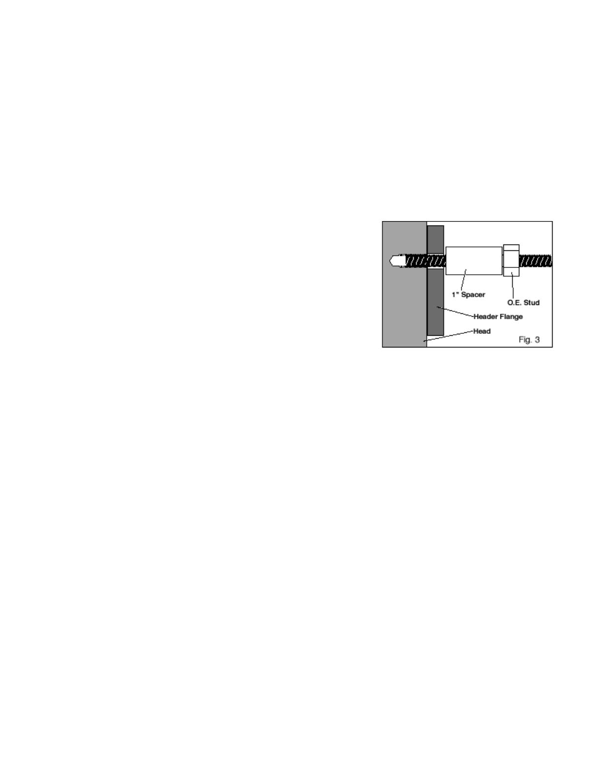
to the lower ange. Bolt the header to the head. Use the supplied 1 ”tubular spacer between the
header ange and the stud shoulder on the front hole. See g.3. Tighten all 6 fasteners.
7. Using the supplied fasteners, bolt the Header to the bottom
ange. The nuts are locking nuts. Therefore they will not spin
freely. Torque to 30-35 ft/lbs.
8. To reinstall the spark plug wire looms, use the supplied 1/2”
tubular spacer and 1/4” bolt. The spark plug wire loom will now
sit outward of the header ange rather than against the head. If
equipped, re-connect the O2 sensor plug.
9. Re-install the modied black steel bracket in the reverse order of removal. First, fasten the brack-
et to the rear of the power steering pump. Maneuver the power steering pump back into its original
position. The steel bracket will now attach to the head with the single stud in the front hole of the
#1 exhaust port. Attach the bracket to the head via the stud in the front hole of the #1 exhaust port.
Fasten the steel bracket to the back of the alternator. Install the three bolts back through the front of
the power steering pump. Reinstall the pulley using the pulley installer. Re-install the serpentine belt.
Re-assemble the fan shroud.
Passenger Side:
10. Unbolt the manifold from the exhaust system from underneath. Remove the dipstick. Disconnect
the spark plug wires from the spark plugs. Unbolt the Spark Plug wire looms and put them up out of
the way. The dipstick tube is bolted to the head via the forward spark plug wire loom bolt. With the
bolt removed, the dipstick tube can be removed by gently wiggling the tube while pulling upward.
(The bottom of the tube is pressed into a hole in the engine.) Remove the exible hot air tube at-
tached to the sheet metal heat stove. (See Figure 4.) Unbolt the manifold from the head and re-
move. As with the driver’s side, clean the head ange and lower ange where the header will attach
to the exhaust system. Remember to remove the doughnut-shaped gasket.
11. Apply anti-seize to the bolts, apply silicone to the dome ange, and bolt the headers to the head
and the exhaust system. Reattach the spark plug looms in the same manner as the driver’s side.
12. If retaining the heat riser, clamp the supplied heat riser adapter to the header using the supplied
hose clamp. Shorten exible heat riser tube to t (about 3-1/2 inches). Take care not to cut the tube
too short. (Err on the long side, you can always make another cut.)
Parts List:
(1) Driver’s Side Header Assembly (6) Collector Bolts, Nuts &Washers.
(1) Passenger’s Side Header Assembly (4) 1/4”I.D. x 1/2” long spacer
(11) 3/8” x 1”header bolts & lock washers (4) 1/4”x 1” bolts
(2) Header gaskets (1) Heat Riser Tube Adapter.
(1) 3/8” I.D. x 1” long spacer (1) Plug for the O2 sensor tting
(2) 90 degree spark plug boots (2) Spark plug wire terminals
(1) CARB EO Sticker
13. On Chevy Suburbans: The rear seat heater has an extra set of coolant hoses passing by the
headers on the passenger side. Take care to keep these hoses back away from the headers. Use ny-
lon ties, or some other method of preventing the heater hoses from contacting the hot header tubes.
14. Start the engine and let it warm up. Check for leaks. Shut engine o and let it cool down. Check to
make sure all fasteners are tight. Periodically check and retighten the header bolts.
  • Page 1 1
  • Page 2 2
  • Page 3 3
  • Page 4 4

JBA PERFORMANCE EXHAUST 1840s User manual

Type
User manual

JBA Performance Exhaust 1840s are designed to provide increased performance and improved exhaust flow for Chevrolet and GMC trucks with 4.3 V6 engines. These headers are constructed from durable materials and feature a mandrel-bent design for optimized flow and power gains. The 1840s headers are compatible with both carbureted and fuel-injected engines, and include all necessary hardware for a hassle-free installation.

Ask a question and I''ll find the answer in the document

Finding information in a document is now easier with AI