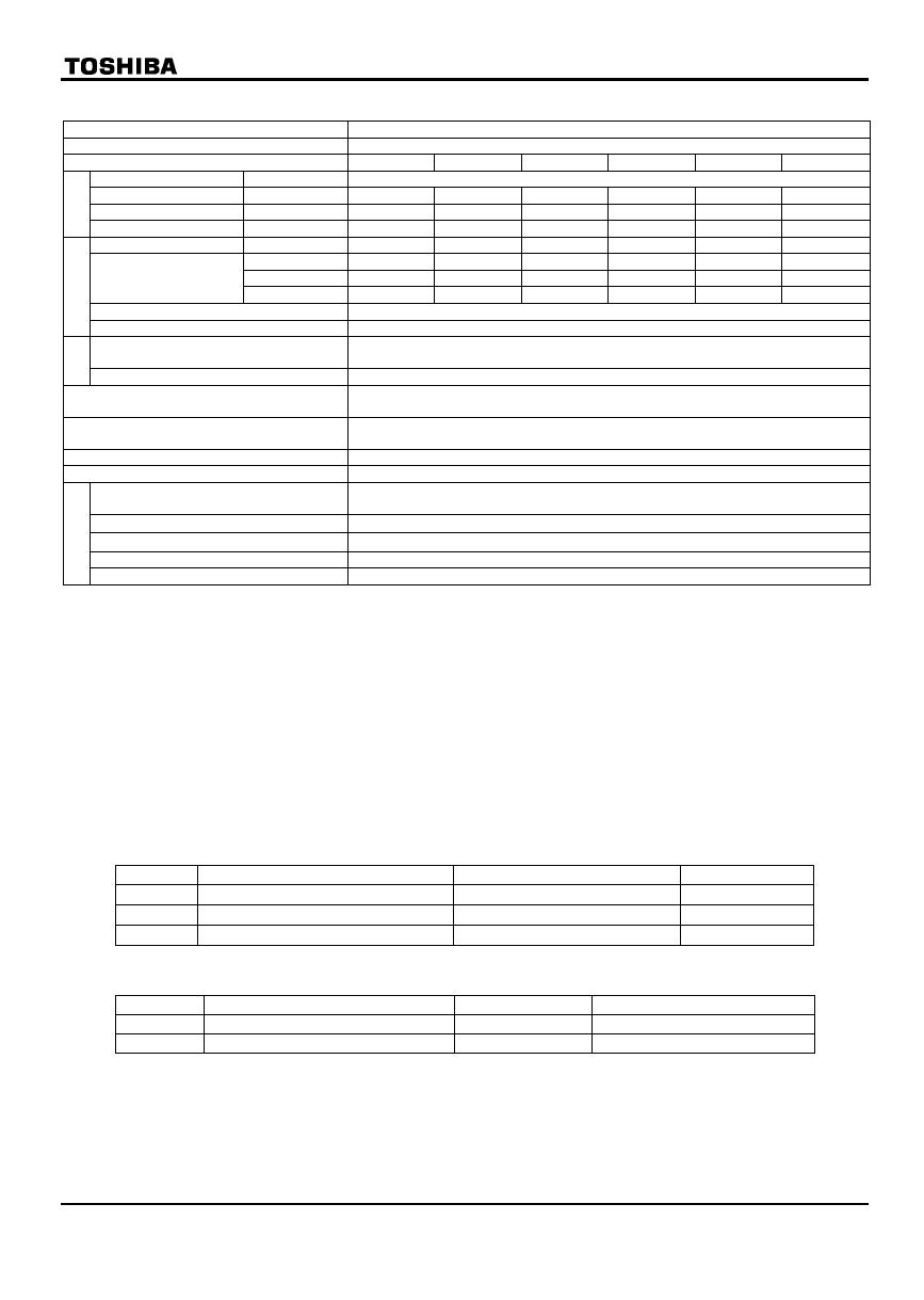
Toshiba VF-S11 User manual

Type
User manual

Toshiba VF-S11 is a totally-enclosed box type inverter designed for industrial use. It offers precise control of motor speed and torque, making it suitable for a wide range of applications, including pumps, fans, conveyors, and machine tools. With built-in protection features and a compact design, the VF-S11 is a reliable and user-friendly choice for demanding industrial environments.

Toshiba VF-S11 is a totally-enclosed box type inverter designed for industrial use. It offers precise control of motor speed and torque, making it suitable for a wide range of applications, including pumps, fans, conveyors, and machine tools. With built-in protection features and a compact design, the VF-S11 is a reliable and user-friendly choice for demanding industrial environments.

E6581225
Instruction Manual (Supplementary)
Totally-Enclosed Box Type Inverter
TOSVERT VF-S11
Thank you for purchasing a Toshiba “Totally-enclosed box type TOSVERT VF-S11 series inverter.”
This Manual gives a supplementary explanation of some items referred to in the instruction manual E6581158
included with the product. Please read this manual carefully along with the instruction manual E6581158.
1-phase 240V class 0.2 to 2.2kW
3-phase 240V class 0.4 to 4.0kW
3-phase 500V class 0.75 to 4.0kW
- To set makers -
Please see to it that this manual is supplied to the inverter’s end user, along with the instruction manual
E6581158.
E6581225
1
Safety precautions
Before reading this manual, please read the following instructions in addition to “I. Safety Precautions,” of the
instruction manual E6581158.
General Operation
Danger
Mandatory Circuit boards are exposed when the front cover is removed. So do not detach the front
cover when the inverter is energized or within 10 minutes after power is turned off.
Doing so could result in electric shock.
Transportation
Warning
Mandatory When handling the inverter unit, hold it by both the sides firmly. If you hold it by the fins
at the upper and lower parts, you could get injured.
E6581225
2
Exterior Features
No. Devices Remarks
(1) Operation panel Equipped with ,, MODE and ENT keys used to set
parameters, a 7-segment LED and a CHARGE lamp.(The
inverter does not have a RUN key, a STOP key and a
potentiometer control, which are provided for VF-S11 standard
series inverters.)
(2) Manual power ON-OFF switch Used to turn on and off power manually. Note 1:
(3) Slots (x 2) reserved for optional devices Slots for optional contact input switches. Note 2:
(4) Operation ON-OFF rotary switch Used to start and stop the inverter.
(5) Potentiometer for frequency setting Used to set the operation frequency of the inverter.
(6) Wiring port plate Steel plate with wiring portsThe effects of noise can be
reduced to some degree by fixing shielded parts of cables with
cable grounds or similar devices. See page 7.
(7) Name plate Label on which the ratings of the inverter unit is printed.
Note 1: The switch has the function of tripping (overcurrent tripping). If the switch is in the Trip position, inspect
the inverter before turning back on the power switch, because the inverter itself may be faulty.
Note 2: Recommended contact input switches: Harmony series (XB5 series)
(2)
(3)
(4)
MODE
ENT
0.0
TOSHIBA
Enter key
Mode key
Down key
Up key
CHARGE lamp
Indicates that high voltage is
still present within the
inverter. Do not open the
cover while this is lit.
(1)
(5)
(6)
(7)
Side view
E6581225
3
Main circuit and control circuit terminal boards
How to remove the front cover
1. Shut off the supply of electricity from the main power supply, and turn the manual power ON-OFF switch to
the OFF position.
2. Ten minutes or more after turning off power, check to be sure that the CHARGE lamp is not lit.
3. Remove the 6 screws* (indicated by the arrows in the figure) around the front cover.
(* 4 screws for single/three-phase 240V-0.75kW models and smaller)
4. Pull the front cover slowly toward you to remove it and detach the control signal cable connector.
How to attach the front cover
1. Attach the control signal cable connector.
2. Attach the front cover.
3. Set and tighten the 6 screws* (indicated by the arrows in the figure) around the front cover.
(* 4 screws for single/three-phase 240V-0.75kW models and smaller)
Caution: Attach the front cover securely.
Or else it does not serve as a protector compliant with IP54.
On top of that, it may become impossible to operate the keys on the operation panel.
About the built-in cooling fan
The inverter has a built-in cooling fan. The cooling fan has a useful life of approximately 30,000 hours (2 to 3
years when operated continuously), so it needs to be replaced periodically.
(Single/three-phase 240V-0.75kW models and smaller are not equipped with cooling fans.)
If the cooling fan does not operate normally, the temperatures of the internal electrical components will rise
high, and as a result their lives will be shortened. So inspect it periodically.
About the useful life of the manual power ON-OFF switch
The manual power ON-OFF switch has a useful life of approximately 5 years (if operated 12 hours per day at
an average yearly ambient temperature of 30°C), so it needs to be replaced periodically.
Control circuit terminal board
Main circuit terminal board 2
Main circuit terminal board 1
Internal cooling fan
Motor output : U/T1, V/T2, W/T3,
Internal DC section : P0, PA/+,
PB, PC/-
Power supply : R/L1, S/L2, T/L3
(Single-phase : R/L1, S/L2)
Screw
Screw
Screw
Screw
Screw Screw
Control signal cable connector
To front cover
E6581225
4
Wiring diagram
(5)
(3)
(4)
(7)
(1)
(6)
(2)
(6)
(1) Input power cable
(2) Output cable
(3) Control cable
(4) Control resistor (optional) cable
(5) Wiring port plate
(6) Grounding terminal
(7) Optional communications device
interconnect cable
(Option)
Cautions
Circuit boards are exposed when the front cover is removed. Since high voltages are applied to some parts of
the circuit board, read Section 2.1, “Cautions on wiring,” of the instruction manual E6581158 carefully before
wiring.
When connecting cables, take care not to damage the circuit board with a screwdriver or a similar tool.
To connect the power cable (to the manual power ON-OFF switch), torque the terminal screw to 1.7N·m
(recommended). (M4 screw)
Never turn on the power ON-OFF switch before attaching the front cover.
Or you could get a shock.
The main circuit terminal board (input power cable) has terminals of a cable pinch type.
Before connecting a cable, strip off its sheath to a length of 10mm or so. Torque: 1.7N·m
Approx. 10mm
E6581225
5
Diagram of cables connected at the factory
< WN type : Sink logic > < WP type : Source logic >
Note: The colors indicated in the above figure refer to the colors of cables.
Installation environment
Operate in areas where ambient temperature ranges from -10°C to
+40°C.
Install the inverter in a well-ventilated place and mount it on a flat metal
plate in portrait orientation. Install the inverter so that it is not inclined
more than ±10° from the vertical.
Leave a space of 10cm or more on the upper and lower sides of the
inverter, and a space of 5cm or more on each side.
The inverter has a built-in cooling fan. The cooling fan has a useful life of
approximately 30,000 hours (2 to 3 years when operated continuously),
so it needs to be replaced periodically. The inverter has a built-in cooling
fan. (Single/three-phase 240V-0.75kW models and smaller are not
equipped with cooling fans.)
If the cooling fan does not operate normally, the temperatures of the
internal electrical components will rise high, and as a result their lives will
be shortened.
So inspect it periodically.
0
Fw
Potentiometer for
frequency setting
Operation ON-OFF
rotary switch
Red
BlueBlue
White Black
PP VIB CC
CCF
5cm or more 5cm or more
10cm or more
10cm or more
VFS11
0
Fw
Potentiometer for
frequency setting
Operation ON-OFF
rotary switch
Red
Blue
Blue
White Black
PP VIB CC
CCF
P24
E6581225
6
Outside dimensions
Outside dimensions (mm)
Voltage
class
Applicable
Motor
kW
Inverter type WHDW1H1D1
Cable port
0.2 VFS11S-2002PLE
0.4 VFS11S-2004PLE
0.75 VFS11S-2007PLE
210 240 177 192 218 14 φ19×3
φ21×1
1.5 VFS11S-2015PLE 215 297 206 197 277 14
1-phase
240V
2.2 VFS11S-2022PLE 230 340 222 212 320 14
φ19×1
φ23×3
0.4 VFS11-2004PME
0.75 VFS11-2007PME 210 240 177 192 218 14 φ19×3
φ21×1
1.5 VFS11-2015PME
2.2 VFS11-2022PME 215 297 206 197 277 14
3-phase
240V
4.0 VFS11-2037PME 230 340 222 212 320 14
φ19×1
φ23×3
0.75 VFS11-4007PLE
1.5 VFS11-4015PLE 215 297 206 197 277 14
2.2 VFS11-4022PLE
3-phase
500V
4.0 VFS11-4037PLE 230 340 222 212 320 14
φ19×1
φ23×3
W1 (Installation dimension)
W
2-R2.75
H1 (Installation dimension)
H
D
9
14
E6581225
7
Specifications
Item Specification
Voltage class 1-phase 240V class/3-phase 240V class/3-phase 500V class
Applicable motor (kW) 0.2 0.4 0.75 1.5 2.2 4.0
Voltage class Model number VFS11S-/VFS11-
1-phase 240V class VFS11S- 2002PLE 2004PLE 2007PLE 2015PLE 2022PLE -
3-phase 240V class VFS11- - 2004PME 2007PME 2015PME 2022PME 2037PME
Model
3-phase 500V class VFS11- - - 4007PLE 4015PLE 4022PLE 4037PLE
Capacity (kVA) Note 1: 0.6 1.3 1.8 3.0 /3.0 /3.1 4.2 6.7 /7.2
1-phase 240V 1.5 (1.5) 3.3 (3.3) 4.8 (4.4) 8.0 (7.9) 11.0 (10.0) -
3-phase 240V - 3.3 (3.3) 4.8 (4.4) 8.0 (7.9) 11.0 (10.0) 17.5 (16.4)
Output current (A)
Note 2: 3-phase 500V - - 2.3 (2.1) 4.1 (3.7) 5.5 (5.0) 9.5 (8.6)
Output voltage Note 3: 240V class: 3-phase 200 to 240V, 500V class: 3-phase 380 to 500V
Rating
Overload current rating 150%-1min., 200%-0.5 sec. (50%-reduction value)
Voltage-frequency 240V class: 1-phase/3-phase 200 to 240V-50/60Hz,
500V class: 3-phase 380 to 500V-50/60Hz
Power
supply
Allowable fluctuation Voltage+10%, -15% Note 4:, Frequency±5%
Protective method Totally enclosed type (JEM1030) compliant with IP54/possible to bring into compliance
with IP55 Note 5:
Cooling method Self-cooled (with a built-in cooling fan. 1-phase/3-phase 240V-0.75kW or smaller:
Cooling fan not provided)
Color Munsel 5Y-8/0.5
Built-in filter 1-phase & 500V class: High-attenuation EMI filter, 3-phase 240V class: Standard filter
Use environments Indoor type. Altitude: Not more than 1000m.
Place free from corrosive and explosive gases
Ambient temperature -10 to +40
Storage temperature -25 to +70
Relative humidity 20 to 93%
Environments
Vibration 5.9m/s2 or less (10 to 55Hz)
Note 1: Capacity is calculated at 220V for the 240V models and at 440V for the 500V models.
Note 2: Indicates rated output current setting when the PWM carrier frequency (parameter F300) is 4kHz or less.
The values between parentheses refer to output currents at PWM carrier frequencies of over 4kHz. They
need to be reduced further at frequencies over 12kHz (If a motor cable over 30m in length is used, it is
necessary to reduce them more. This means that the lives of the internal components will be shortened).
When the input power voltage of the 500V class model exceeds 480V, it is necessary to further reduce
the setting. The default setting of the PWM carrier frequency is 12kHz.
Note 3: The maximum output voltage is equal to the input supply voltage.
Note 4: ±10% when the inverter is operated continuously (under a load of 100%).
Note 5: IP54-compliant structures refer to structures that protect the contents from dust and harmful effects of
water that drops from every direction.
The inverter can be brought into compliance with IP55 specifications by making the wiring port watertight.
(IP55-compliant structures refer to structures that protect the contents from dust and harmful effects of
water that comes in a jet from every direction.)
To bring the inverter into compliance with IP-55, use PG screw type cable grounds. Among cable grounds
available are skin-top grounds manufactured by LAPP (Germany).
When using this type of grounds, use them in combination with lock nuts specified below.
Cable port Cable ground Cable ground(EMC-compliant) Lock nut
φ19 hole MS11 MS-SC11 SM-11
φ21 hole MS13.5 MS-SC13.5 SM-13.5
φ23 hole MS16 MS-SC16 SM16
Note 6: For control specifications, parameters and functions, refer to the instruction manual E6581158.
Note 7: The factory default settings of the following parameters are different from those of the VFS-11 standard
type.
Title Function Standard VF-S11 Totally enclosed type VF-S11
cmod Command mode selection 10
fmod Frequency setting mode selection 02
Note 8: The inverter has a built-in cooling fan. The cooling fan has a useful life of approximately 30,000 hours (2
to 3 years when operated continuously), so it needs to be replaced periodically.
(Single/three-phase 240V-0.75kW models and smaller are not equipped with cooling fans.)
If the cooling fan does not operate normally, the temperatures of the internal electrical components will
rise high, and as a result their lives will be shortened. So inspect it periodically.
Note 9: The manual power ON-OFF switch has a useful life of approximately 5 years (if operated 12 hours per
day at an average yearly ambient temperature of 30°C), so it needs to be replaced periodically.
  • Page 1 1
  • Page 2 2
  • Page 3 3
  • Page 4 4
  • Page 5 5
  • Page 6 6
  • Page 7 7
  • Page 8 8

Toshiba VF-S11 User manual

Type
User manual

Toshiba VF-S11 is a totally-enclosed box type inverter designed for industrial use. It offers precise control of motor speed and torque, making it suitable for a wide range of applications, including pumps, fans, conveyors, and machine tools. With built-in protection features and a compact design, the VF-S11 is a reliable and user-friendly choice for demanding industrial environments.

Ask a question and I''ll find the answer in the document

Finding information in a document is now easier with AI