Page is loading ...

L8542697
05/2011 R0
BILL50
UNIONE NAZIONALE COSTRUTTORI
AUTOMATISMI PER CANCELLI, PORTE
SERRANDE ED AFFINI

4
3
4
2
1 BILL SX
5
3x1,5 min.
230Vac**
2
1 BILL DX
2x1,5
2x0,5
2x0,5
4x0.75*
4x0.75*
2x1*
2x1*
4x0,5
RG 58
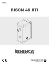
Légende:
1 Moteur-réducteur BILL
2 Photocellule
3 Selecteur à clé
(d’extérieur) ou clavier digital
4 Clignotant
5 Centrale électronique.
Leyenda:
1 Motorreductor BILL
2 Fotocélulas
3 Selectores a llave (de superficie).
4 Relampagueador.
5 Central electrónica.
Objaśnienia:
1 Siłownik BILL
2 Fotokomórki
3
Przełącznik kluczowy (zewnętrzny)
lub panel
z przyciskami
4 Światło migające
5 Centralka elektroniczna
Legenda:
1 Motoriduttore BILL
2 Fotocellule
3
Selettore a chiave (da esterno)
o tastiera digitale
4 Lampeggiante
5 Centrale elettronica
Legenda:
1 Motoreducer BILL
2 Photo-electric cells
3 Key selector (external)
or digital keyboard
4 Flash-light
5 Electronic board.
Zeichenerklärung:
1 Getriebemotor BILL
2 Fotozelle
3 Schlüssel-Selektor (außenliegend)
oder Digital-Tastatur
4 Blinker I
5 Elektroschrank.
Collegamenti elettrici / Wire diagram / Elektrische Anschlüsse
Branchements électriques / Conexiones eléctricas / Połączenia elektryczne
*Tenere separati i cavi di potenza da quelli ausiliari.
BILL 50: Utilizzare un cavo 4x0,75mm²
BILL 5024: Per una lunghezza cavo inferiore a 5m utilizzare un cavo 2x1mm².
Per un lunghezza cavo da 5m fino a 10m utilizzare un cavo 2x2mm². Collegamenti
tra centrale e motore di lunghezza superiore ai 10m sono sconsigliati.
** 115 Vac per la versione BILL30MA.
The power cables must be kept separated from the auxiliary cables.
BILL 50: Use a 4x0.75mm² cable
BILL 5024: With cables less than 5m long, use a 2x1mm² cable. With cables
with a length ranging from 5 to 10 m, use a 2x2mm² cable. Connecting cables
between control unit and motor longer than 10m are not recommended.
** 115 Vac for the BILL50MA model.
Leistungskabel von Hilfskabeln getrennt halten.
BILL 50: ein Kabel 4x0,75mm² verwenden
BILL 5024: Bei einer Kabellänge von weniger als 5 m muss ein Kabel 2x2,5mm2
verwendet werden. Bei einer Länge von 5 m bis 10 m muss ein Kabel 2x2mm²
verwendet werden. Anschlüsse zwischen Zentrale und Motor in einem größeren
Abstand als 10 m sind nicht zu empfehlen.
** 115 Vac für Ausführung BILL50MA.
Séparer les câbles de puissance des câbles auxiliaires.
BILL 50: Utiliser un câble de 4x0,75mm²
BILL 5024: Si le câble a une longueur inférieure à 5m utiliser un câble de
2x1mm². Pour un câble de longueur entre 5m et 10m utiliser un câble de
2x2mm². Tout branchement entre la centrale et le moteur ayant une longueur
supérieure à 10m est déconseillé.
** 115 Vac pour la version BILL 50MA.
Tener separados los cables de potencia de los auxiliares.
BILL 50: Utilizar un cable 4x0,75mm²
BILL 5024: Para un cable largo menos de 5m utilizar un cable 2x1mm². Para un cable
largo entre 5m y 10m utilizar un cable 2x2mm². Se desaconsejan las conexiones
entre la central y el motor de más de 10m de longitud.
** 115 Vac para la versión BILL50MA.
Należy trzymać w oddali przewody zasilania od przewodów pomocniczych.
BILL 50: Użyć kabla 4x0,75mm²
BILL 5024: Jeżeli długość nie przekracza 5m użyć kabla 2x1mm². W przypadku
długości w przedziale od 5 do 10 m użyć kabla 2x2mm². Zaleca się, aby
połączenia między silnikiem a centralką nie przekraczały 10m.
** 115 Vac dla wersji BILL50MA.
5

8
EC Declaration of Conformity
Directive 2004/108/EC(EMC); 2006/95/EC (LVD)
Manufacturer: Automatismi Benincà SpA.
Address: Via Capitello, 45 - 36066 Sandrigo (VI) - Italia
Herewith declares that: the operator for hinged gates model BILL 50M - BILL 50MA.
is complying with provisions set forth by the following other EC Directive:
- DIRECTIVE 2004/108/EC OF THE EUROPEAN PARLIAMENT AND OF THE COUNCIL of 15 December 2004,
on the harmonisation of the laws of Member States relating to electromagnetic compatibility and which cancels
Directive 89/336/EEC, according to the following harmonised regulations: EN 61000-6-2:2005, EN 61000-6-
3:2007.
- DIRECTIVE 2006/95/EC OF THE EUROPEAN PARLIAMENT AND OF THE COUNCIL of 12 December 2006, on
the harmonisation of the laws of Member States relating to electrical equipment designed for use with certain
voltage limits, according to the following harmonised regulations: EN 60335-1:2002 + A1:2004 + A11:2004 +
A12:2006 + A2:2006 + A13:2008; EN 60335-1-103:2003.
Benincà Luigi, Legal responsible.
Sandrigo,10/04/2011.
EC Declaration of Conformity
Directive 2004/108/EC(EMC); 2006/95/EC (LVD)
Manufacturer: Automatismi Benincà SpA.
Address: Via Capitello, 45 - 36066 Sandrigo (VI) - Italia
Herewith declares that: the operator for hinged gates model BILL 5024.
is complying with provisions set forth by the following other EC Directive:
- DIRECTIVE 2004/108/EC OF THE EUROPEAN PARLIAMENT AND OF THE COUNCIL of 15 December 2004,
on the harmonisation of the laws of Member States relating to electromagnetic compatibility and which cancels
Directive 89/336/EEC, according to the following harmonised regulations: EN 61000-6-2:2005, EN 61000-6-
3:2007.
Benincà Luigi, Legal responsible.
Sandrigo,10/04/2011.

9
Introduction
Electromechanical operator to activate swing gates,
available in the following models:
BILL50M: with motor powered at 230 VAC.
BILL50MA: with motor powered at 115 VAC.
BILL5024: with motor powered at 24 VDC.
For 5very model, the RGHT (DX) version is also
available to install the system on the right gate leaf,
and the LFT (SX) version is available for installation on
the left gate leaf.
In case of doubt, as shown in the instruction manual,
the wording DX (right) or SX (left), which identifies the
different models, can be seen by opening the release
handle.
For simplicity reasons, this manual shows the SX
motor for left gate leaves. For the DX (right) versions,
installation dimensions and instructions are the
same.
The main dimensions are shown in Fig. 1.
t #FGPSF JOTUBMMJOH UIF TZTUFN SFBE UIF JOTUSVDUJPO
herein.
t *U JT NBOEBUPSZ OPU UP VTF UIF #*-- JUFN GPS
applications different from those indicated in the
instructions herein.
t 4VQQMZUIFFOEVTFSXJUIJOTUSVDUJPOTGPSVTJOHUIJT
system.
t
The end user should receive special instruction manual.
t "MM#FOJODËJUFNTBSFDPWFSFECZBOJOTVSBODFQPMJDZ
for damages and injuries caused by manufacture
faults. It is however required that the machine
bear the CE marking and original Benincà parts be
used.
General information
To ensure a good operation of these automatic devices,
the gate to be automated should meet the following
requirements:
- good strength and stiffness.
- hinges should have a minimum backlash and allow
for smooth and regular manual operations.
- when closed, the gate leaves should correctly
overlap for their entire height.
Warning: BILL50 is not equipped with electric limit
switches or mechanical stoppers. It is mandatory that
the gate leaf be equipped with mechanical stoppers
fitted to the ground (Fig.2 ref. A and B).
Operating limits
The following tables show the permitted maximum
weight and width figures of the gate leaves.
BILL 50M / BILL 50MA
Max gate leaf weight (kg) 250 350 400 500 600 700
Max gate leaf (m) 5,0 4,5 4,0 3,5 3,0 2,5
BILL 5024
Max gate leaf weight (kg) 200 300 350 450 500 600
Max gate leaf (m) 5,0 4,5 4,0 3,5 3,0 2,5
IMPORTANT: For gate leaves wider than 4.00 mt,
an electric lock is required.
How to install the system
1) Define the height of the system from ground (the
most centred possible with respect to the main door
and corresponding to a rugged crossbeam).
2) Weld the P plate, taking account of figures X and Y
of Fig. 2/3.
3) Release the actuator, as shown in the instruction
manual. When the gate is closing, temporarily lock the
S* bracket by keeping the K measure as per Fig. 2/3. In
these conditions, the actuator must not be positioned
entirely at end of stroke, but 10mm extra-stroke should
The product shall not be used for purposes or in ways
other than those for which the product is intended for and
as described in this manual. Incorrect uses can damage
the product and cause injuries and damages.
The company shall not be deemed responsible for the
non-compliance with a good manufacture technique of
gates as well as for any deformation, which might occur
during use.
Keep this manual for further use.
Qualified personnel, in compliance with regulations in
force, shall install the system.
Packaging must be kept out of reach of children, as it can
be hazardous. For disposal, packaging must be divided
the various types of waste (e.g. carton board, polystyrene)
in compliance with regulations in force.
The installer must supply all information on the automatic,
manual and emergency operation of the automatic sy-
stem and supply the end user with instructions for use.
;
An omnipolar switch/section switch with remote
contact opening equal to, or higher than 3mm
must be provided on the power supply mains..
Make sure that before wiring an adequate differential
switch and an overcurrent protection is provided.
Pursuant to safety regulations in force, some types of in-
stallation require that the gate connection be earthed.
During installation, maintenance and repair, cut off power
supply before accessing to live parts.
Descriptions and figures in this manual are not binding.
While leaving the essential characteristics of the product
unchanged, the manufacturer reserves the right to modify
the same under the technical, design or commercial point
of view without necessarily update this manual.
WARNING

10
be still available.
By manually opening the gate leaf, check that the
actuator does not hit the leaf or the pillar.
4) Only after this check, carry out the final welding of
the S bracket. The actuator should be perfectly flat.
Important: the respect of dimensions indicated in Fig. 3
ensures the optimal operation of the automatic system.
These different dimensions may cause malfunctions.
In any case, the manufacturer shall be held
unharmed with respect to damages caused by the
non-respect of the dimensions indicated.
If it is not possible to carry out welding, adjustable
brackets, which can be mounted by using screws (art
B.SR), are available as optional accessory.
Fix the actuator to the bracket by means of screws and
nuts supplied. Use washers as shown in Fig. 4.
Note: The difference between measures X and Y shall
be never exceed 40mm. Greater differences cause the
unsmooth movement of the gate.
Dimensions M and X should be carefully checked to
avert that the actuator hits the pillar (dim. M) or the
leaf (dim. Z).
The total stroke of the actuator is around 520mm. The
stroke, however, cannot be entirely used. An extra
stroke of around 10 mm should be always provided
both in the closing and opening phases.
* In the BILL 50 geared motor, the difference in height
of brackets P and S shall be nil. These brackets should
be therefore fitted at the same height (Fig. 1, ref. A}
Wire connections
BILL 50 is supplied with a pre-cabled wire, around 80
cm long, to be connected to the junction box fitted to
the pillar.
BILL 50:
In the 230V model, the cable includes 4 terminals:
BLACK Gear 1
BROWN Gear 2
GREY Motor, common
Yellow/Green Earth
BILL 5024:
In the 24V model, the cable includes 2 terminals (BLUE/
BROWN)
Note:
The motor cable shall be replaced only by an authorised
assistance centre.
IT IS MANDATORY to connect the system to ground
by using the special GND terminal, as provided by
regulations in force.
WARNING
The insurance policy, which covers any damages or
injuries caused by manufacture faults, requires that
the installation comply with regulations in force and
Benincà original accessories be used.
TECHNICAL DATA
BILL 50M BILL 50MA BILL 5024
Motor power supply
230Vac
50/60Hz
115 Vac
50/60Hz
24Vdc
Consumption 1,35 A 2,7 A 5 A
Max. thrust 3200 N 3200 N 2000 N
Operating jogging 30 % 30 % Heavy duty
Protection level IP54
Operating temperature -20°C / +50°C
Capacitor 10 μF 36 μF -
Useful stroke 500 mm
Noise <70 dB
Lubrication Permanent grease
Weight 7,1 kg 7,1 kg 5,5 kg

24
Sicherheitsvorschriften
t /JDIUJN½GGOVOHTCFSFJDIWFSXFJMFO
t
Kinder nicht mit den Steuerungen oder in der Nähe des Tores spielen lassen.
t #FJ'VOLUJPOTBVTGÊMMFOOJDIUWFSTVDIFOEFO4DIBEFOTFMCFS[VCFIFCFOTPOEFSOEFO5FDIOJLFSSVGFO
Hand- und Notbedienung
Bei einem Stromausfall oder im Falle einer Störung, kann der Torflügel folgendermaßen von Hand gesteuert werden:
t%JF4DIMPTT7FSTDIMVTTLMBQQFOBDIBVFOESFIFO"CC"3FG$
t%FOTQF[JFMMFO&OUTJDIFSVOHTTDIMàTTFMNJUHFMJFGFSUFJOTUFDLFOVOEVN¡HFHFOEFO6IS[FJHFSTJOOCFJMJOLFN.PUPSPEFSJN
Uhrzeigersinn bei rechtem Motor drehen
t%FO&OUTJDIFSVOHTHSJGGXJFJO"CCJMEVOH#3FG. HF[FJHUESFIFO%FS)FCFMIBU FJOF"VTHBOHTC[X 4UPQQQPTJUJPOEJF
überschritten werden muss (Klick!), um die Mechanik zu entsichern.
t%FO)FCFMWPMMLPNNFOÚGGOFOVNDB¡ESFIFO(FHFO&OEFJTUFJOMFJDIUFS8JEFSTUBOE[VCFNFSLFO
t/VOLBOOEFS5PSnàHFMWPO)BOEHFÚGGOFUC[XHFTDIMPTTFOXFSEFO
t6NEFOBVUPNBUJTDIFO#FUSJFCXJFEFSIFS[VTUFMMFOEFO)FCFMJOEJF"VTHBOHTQPTJUJPO[VSàDLCSJOHFOVOEEFO4DIMàTTFOVN
90° drehen. Die Verschlussklappe des Schlosses wieder schließen.
Wartung
t .POBUMJDIF,POUSPMMFEFSNBOVFMMFO/PUFOUSJFHFMVOH
t
Es ist absolut untersagt, selbstständig Sonderwartung oder Reparaturen vorzunehmen, da Unfälle die Folge sein können; wenden Sie sich
an den Techniker.
t %FS"OUSJFCCSBVDIULFJOFPSEFOUMJDIF6OUFSIBMUVOHBCFSFTJTUQFSJPEJTDIOPUXFOEJHEJF-FJTUVOHTGÊIJHLFJUEFS4JDIFSIFJUTWPS-
richtungen und die andere Teile des Anlages zu prüfen. Sie könnten durch Abnutzung Gefaht hervorbringen.
DEUTSCH
ENGLISH
Safety rules
t%POPUTUBOEJOUIFNPWFNFOUBSFBPGUIFEPPS
t%POPUMFUDIJMESFOQMBZXJUIDPOUSPMTBOEOFBSUIFEPPS
t4IPVMEPQFSBUJOHGBVMUTPDDVSEPOPUBUUFNQUUPSFQBJSUIFGBVMUCVUDBMMBRVBMJmFEUFDIOJDJBO
Manual and emergency operation
In the event of power failure or faults, the gate can be manually operated as follows:
tUVSOUIFEPPSDPWFSJOHUIFMPDL'JH"oSFG$
t*OUSPEVDFUIFSFMFBTFLFZTVQQMJFEBOEUVSOJUCZ¡BOUJDMPDLXJTFGPSUIFMFGUNPUPSBOEDMPDLXJTFGPSUIFSJHIUNPUPS
tUVSOUIFSFMFBTFIBOEMFBTJOEJDBUFEJOmHVSF#SFG.UIFMFWFSIBTBTUPQJOJUJBMQPTJUJPOUIBUNVTUCFPWFSDPNFDMJDLUPCF
heard) to actually act on the mechanical release;
tNPWFUIFMFWFSUPUPUBMMZPQFOQPTJUJPOBSPVOE¡SPUBUJPO5PXBSETUIFFOEUIFMFWFSNPWFNFOUXJMMCFTMJHIUMZTUJGGFS
tUIFHBUFMFBGDBOCFPQFOFEPSDMPTFECZIBOE
tUPSFTFUUIFBVUPNBUJDPQFSBUJPONPWFUIFIBOEMFUPUIFJOJUJBMQPTJUJPOUVSOUIFLFZCZ¡BOEDMPTFUIFEPPSDPWFSJOHUIFMPDL
Maintenance
t
Every month check the good operation of the emergency manual release.
t*UJTNBOEBUPSZOPUUPDBSSZPVUFYUSBPSEJOBSZNBJOUFOBODFPSSFQBJSTBTBDDJEFOUTNBZCFDBVTFE5IFTFPQFSBUJPOTNVTUCFDBSSJFE
out by qualified personnel only.
t5IFPQFSBUPSJTNBJOUFOBODFGSFFCVUJUJTOFDFTTBSZUPDIFDLQFSJPEJDBMMZJGUIFTBGFUZEFWJDFTBOEUIFPUIFSDPNQPOFOUTPGUIF
automation system work properly. Wear and tear of some components could cause dangers.
Waste disposal
As indicated by the symbol shown, it is forbidden to dispose this product as normal urban waste as some parts might
be harmful for environment and human health, if they are disposed of incorrectly. Therefore, the device should be
disposed in special collection platforms or given back to the reseller if a new and similar device is purchased. An
incorrect disposal of the device will result in fines applied to the user, as provided for by regulations in force.
Warning
All Benincá products are covered by insurance policy for any possible damages to objects and persons caused by construction faults
under condition that the entire system be marked CE and only Benincá parts be used.

27
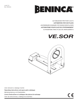
1
2
5
6
10
9
8
4
3
7
BILL 5024
Ref.
BILL 50M DX
Code
BILL 50M SX
Code
BILL 50MA DX
Code
BILL 50MA SX
Code
BILL 5024 DX
Code
BILL 5024 SX
Code
NOTE
1
9686592 9686591 9686594 9686593 9686594 9686593
2
9686594 9686593 9686594 9686593 9686594 9686593
3
9686595 9686595 9686595 9686595 9686595 9686595
4
9686596 9686596 9686596 9686596 9686597 9686597
5
9686602 9686603 9686604 9686605 --- ---
6
9686599 9686599 9686599 9686599 9686601 9686601
7
9686279 9686279 9686653 9686653 --- ---
8
9686652 9686652 9686652 9686652 9686652 9686652
9
--- --- --- --- 9686606 9686606
10
--- --- --- --- 9686607 9686607
/