Page is loading ...

Model 7000
Service Manual
IMPORTANT: Fill in Pertinent Information on Page 3 for Future Reference

Job Specication Sheet ......................................................................................................................................... 3
Water Softener Control Valve ................................................................................................................................ 4
Valve Installation and Start-Up Procedures ........................................................................................................... 5
7000 Control Operation and Settings .................................................................................................................... 6
Programming a Meter Delayed Regeneration System .......................................................................................... 9
Programming a Meter Immediate Regenerated System ......................................................................................11
Programming a Time Clock Regenerated System .............................................................................................. 12
Programming a Day of the Week Regenerated System ...................................................................................... 14
Water Conditioner Flow Diagrams ....................................................................................................................... 16
Power Head Assembly ........................................................................................................................................ 20
Valve Assembly ................................................................................................................................................... 22
Bypass Assembly ................................................................................................................................................ 24
2310 Safety Brine Valve ...................................................................................................................................... 25
Troubleshooting ................................................................................................................................................... 26
Removing Gear Box Assembly ............................................................................................................................ 28
Inserting Circuit Board ......................................................................................................................................... 29
Connecting the Circuit Board............................................................................................................................... 30
Dimensions .......................................................................................................................................................... 31
Meter Flow Data .................................................................................................................................................. 32
Injector Flow Data................................................................................................................................................ 33
Table of Contents
IMPORTANT: The information, specications and illustrations in this manual are based on the latest information
available at the time of printing. The manufacturer reserves the right to make changes at any time without notice.

Job Number:
Model/Serial Number:
Water Test:
Capacity Of Unit: Max: Per Regeneration:
Brine Tank Size:
Salt Setting per Regeneration:
Treated Water Capacity (Gallons/Liters)
Regeneration Day Override (Max Days Between Regen)
Regeneration Time (AM/PM)
Type of Timer (with Meter/without Meter)
Notes
Page 3
Job Specication Sheet

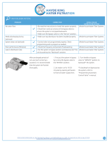
Water Pressure
A minimum of 20 psi inlet water pressure is required for regeneration valve to operate effectively.
Electrical Facilities
An uninterrupted alternating current (A/C) supply is required. Make sure:
• Voltage supply is compatible with unit before installation.
• Current supply is always hot and cannot be turned off with another switch.
Existing Plumbing
Condition of existing plumbing should be free from lime and iron buildup. Replace piping that has heavy lime and/
or iron build-up. If piping is clogged with iron, install a separate iron lter unit ahead of the water softener.
Location of Softener and Drain
Locate the softener close to a clean working drain and connect according to local plumbing codes.
Bypass Valves
Always provide for the installation of a bypass valve if unit is not equipped with one.
Water Softener Control Valve
Page
NOTE:
This product should be installed by qualied personnel.
Comply with all plumbing codes when installing this product.
Comply with all electrical codes when installing this product.
CAUTION
•Minimum water pressure 20psig.
•Maximum water pressure 125psig.
•Minimum water temperature 34° F.
•Maximum water temperature 110° F.
•Ambient temperature 34° to 122° F (1° to 50° C)
•Disconnect all power sources before servicing.
•Always operate with cover in place.
WARNING
The controller MUST be depressurized before removing
any quick connection clips for servicing. The connector
should be pushed toward the control while removing clips.

Installation Instructions
1. Place the softener tank where you want to install the unit.
NOTE: Be sure the tank is level and on a rm, clean base.
2. Perform all plumbing according to local plumbing codes.
3. Cut the 1.05” or 32mm distributor tube ush with the top of the tank (A).
— Deburr the outside of the tube (B) after cutting.
— Lubricate the o-ring (C) with non-petroleum based grease.
. Lubricate the distributor 0-ring seal and tank 0-ring seal.
Use only non-aerosol silicone lubricant.
5. Load media and place the control valve on the tank.
6. All soldering MUST be done on any connections requiring soldering prior to connecting the main control
valve.
The main control valve will by damaged if it is connected at the time of soldering.
7. Apply Teon tape to all threaded ttings.
8. On units with a bypass, place in Bypass position.
— Turn on the main water supply.
— Open a cold soft water tap nearby and let water run a few minutes or until the system is free of foreign
material (usually solder) resulting from the installation. Close the water tap when water runs clean.
9. Make plumbing connections to valve.
10. Plug the valve into an approved power source.
NOTE: Make all electrical connections according to codes.
11. Place the bypass In Service position. Cycle the valve to the Backwash position, and let the water ow slowly
into the mineral tank until the air is purged from the unit.
12. Add water to the brine tank until the top of the air check is covered. Manually step the valve to the Brine Draw
Position, and allow the valve to draw water from the brine tank until it stops.
NOTE: The air check will check at approximately the midpoint of the screened intake area.
13. Manually step the valve to the Brine Rell Position, and allow the valve to return to In Service automatically.
1. With the valve In Service, check that there is at least 1” of water above the grid in the brine tank, if used.
15. Fill the brine tank with salt.
16. Allow the control to run automatically. Setup is now complete.
Valve Installation and Start-Up Procedures
Page 5

Time Clock or Day of the Week Regeneration Valves
In normal operation the Time of Day Display may be viewed at all times. The control operates for a preset
number of days between Regeneration cycles. When the number of days since the last Regeneration reaches
the preset number of days, a Regeneration cycle initiates at the preset Regeneration Time.
Program the number of days between Regeneration cycles and the Regeneration time using the 7000 Control
Start-Up Procedures.
Flow Meter Equipped Valves – General
Flow meter equipped valves calculate the volume of water that the system can treat between Regeneration
cycles based on the system capacity which is preset by the system manufacturer in a Master Programming
Mode and the feed water hardness which is programmed in the Start-Up procedure safety factor (Master
Mode only).
The remaining system capacity displays in gallons or liters. The display has a range of 0 to 9999 (gallons or
liters). If the remaining capacity exceeds 9999 liters when in the Metric Mode, then the display changes to
millions of liters and a letter t is displayed as the rst digit. The display then has a range of t1.0 (1,000,000) to
t1.9 (1,900,000).
Flow Meter Equipped Valves – Immediate Regeneration Mode
The Time Of Day display alternates with the Volume Remaining display in gallons or liters. The Meter dot
ashes in direct relation to the water ow rate through the unit. As treated water is used, the Volume Remain-
ing display counts down from a maximum value to zero and initiates a Regeneration cycle immediately.
7000 Control Operation and Settings
Page 6
Display
Program Indicator
Programming Mode Active, Light On
In Service Indicator
Valve In Service, Light On
Manual Regeneration Qued, Flashing Light
Flow Indicator
Water Flow, Light Flashing
P.M. Indicator/Valve Moving Light Flashing
P.M., Light On
A.M., Light Off
Display Screen
Time of Day alternates with Process Display
(for example, Volume Remaining, Time Remaining,
Programming Information), Error Codes
Set Down Button
Adjust Values Down
Set Up Button
Adjust Values Up
Extra Cycle Button
User-Initiated and Program Step Advance Regeneration

Flow Meter Equipped Valves – Delayed Regeneration Mode
In Normal operation the Time Of Day display alternates with the Volume Remaining display. The ow dot
ashes in direct relation to the water ow rate through the unit. As treated water is used, the Volume Remain-
ing display counts down from a maximum value to zero. If the reserve is reached, a Regeneration queues.
The display shows all dashes if the entire volume is depleted before the scheduled Regeneration time. At the
preset Regeneration Time, a Regeneration cycle initiates.
Control Operation During Regeneration
In Regeneration the display shows the Regeneration status two ways:
• When the valve advances to the next position, the display ashes the number of that next position
followed by three dashes.
• Once the valve reaches a position the display shows that position and number of minutes left in that
Regeneration step.
NOTE: If the step time exceeds 100, the leading digit ashes.
• Once all Regeneration steps are complete, the valve returns to In Service and resumes normal
operation.
NOTE: Pressing the Extra Cycle Button during a Regeneration cycle immediately advances the valve to
the next cycle step position and resumes normal step timing.
Control Operation During Programming
The control enters Program Mode with the valve In Service. While in Program Mode the control continues to
operate normally, monitoring water usage and keeping all displays up to date. Control programming is stored
in memory permanently. There is no need for battery backup power.
Control Operation During a Power Failure
During a power failure all control displays and programming are stored for use upon power re-application. An
inaccurate or ashing Time of Day display indicates that a power outage has occurred. During power failure
the control:
• Is fully inoperative and any calls for Regeneration are delayed.
• Upon power re-application, resumes normal operation from the point that it was interrupted.
• Does not monitor the volume of water used during a power outage.
• In Delay Regeneration types, the reserve capacity is set to 1/3 the capacity.
Manually Initiating a Regeneration
A Regeneration cycle may be initiated manually (referred to as an Extra Regeneration Cycle). There are two
options when starting an Extra Regeneration Cycle:
• Press and release the Extra Cycle Button:
— Flow Meter - Immediate Regeneration controls immediately go into a Regeneration cycle.
— For Time Clock and Flow Meter - Delayed Regeneration controls, the In Service dot begins to ash
immediately and a Regeneration occurs at the pre-programmed Regeneration time.
7000 Control Operation and Settings
Page 7
• Press and hold the Extra Cycle Button for ve (5) seconds:
— For Time Clock and Flow Meter - Delayed Regeneration controls, the control immediately begins the
Regeneration cycle.

Set Time of Day
• Press the Set Up and Set Down buttons to set time of day.
— Metric = 2 hour clock
— US = 12 hour clock with PM indicator light
7000 Control Start-Up Procedures
Page 8
Enter Control Programming Mode
— Press and hold both the Set Up and Set Down buttons for 5 seconds to enter
Programming Mode. When the program mode is entered, the program dot turns on.
The 7000 controller performs 5 basic types of Regeneration systems. The type of system is selected by the sys-
tem manufacturer and set in the Master Programming Mode. Basic systems are:
• Time Clock
— The control operates for a preset number of days between Regeneration cycles. On the day that a
Regeneration cycle is required the system regenerates at the preset Regeneration Time.
• Meter Immediate
— The control regenerates immediately when the remaining capacity (volume of water that can be
treated before a Regeneration is required) drops to 0.
• Meter Delayed
— The control regenerates on the day that the remaining capacity drops to less than the reserve volume.
Regeneration starts at the preset Regeneration Time.
• Meter Delayed - Variable Brining
— The control regenerates on the day that the available volume of softened water drops to or below the
reserve volume. Regeneration starts at the set Regeneration Time. With the variable brining option
activated, the time setting for Cycle 1 is automatically calculated based on the volume of treated water
at the time of regeneration. Cycle time 1 will not exceed the original time setting and is never less than
1 minute.
• Day of the Week
— The control regenerates at the scheduled Regeneration Time on the day(s) of the week which are set
by the user.
The Current Day of the Week display will alternate with the Time of Day when the control is In Service.
The Day of the Week display will increment each day at 12:00 A.M. (Midnight).

1. Feed water hardness (Display Code H).
NOTE: The feed water hardness setting only displays when the system is set to operate as a Meter
Immediate or Meter Delayed system type.
— Press the Set Up or Set Down buttons to set the amount of feed water hardness in grains/gallon
(U.S.) or degrees (metric). The system automatically calculates treated water capacity based on the
feed water hardness and the system capacity preset in the Master Programming mode. “Calc” is
displayed during calculations.
Example: Range: 4 – 199 U.S. and metric
— To program 9 grains / gallon (U.S.) or 9 degrees (metric) [ H -- 9]
— Press the Set Up and Set Down buttons to adjust this value.
— Press the Extra Cycle button once to advance to the next step.
Programming a Meter Delayed Regenerated System
Page 9
2. Regeneration Time (No display Code)
NOTE: The Regeneration Time setting does not display in Meter Immediate Regeneration Mode since the
system regenerates immediately when the available capacity reaches 0.
Identify the Regeneration Time display by observing a non-ashing colon between two sets of numbers. Set
the desired time of day for Regeneration to occur.
Example: 2 o’clock A.M. regeneration time: [ 2:00 ] (P.M. Indicator Dot Off)
— Press the Set Up and Set Down buttons to adjust this value.
— Press the Extra Cycle button to exit the programming mode or press and hold the Set Up and Set Down
buttons simultaneously for ve (5) seconds to enter the Extended Setup Programming Mode.

Programming a Meter Delayed Regenerated System
Page 10
3. EXTENDED Programming Mode
Regeneration Cycle Step Programming (Display Code 1 to 6)
Use this feature to program the Regeneration Cycle step times. The Regeneration Cycle Step being
programmed appears in the rst digit of the display. Each display is used to set the duration time in minutes of
that specic step in the regeneration cycle.
Example:
Cycle Step dF dFFF FLtr
1 10 = Backwash 12 = Fill 10 = Backwash
2 60 = Brine Draw 60 = Brine Making 10 = Rapid Rinse
3 5 = 2nd Backwash 10 = Backwash
10 = Rapid Rinse 60 = Brine Draw
5 12 = Rell 5 = 2nd Backwash
6 10 = Rapid Rinse
— Use the Set Up and Set Down buttons to adjust this value.
— Press the Extra Cycle button to advance to the extended diagnostics.
4. EXTENDED Diagnostics Mode (Viewable Only)
(Dy xx) Display Code xx = days since last Regeneration
— Press the Extra Cycle button once to advance to the next diagnostics.
(xxxx) No Display Code xxxx = volume used since the last Regeneration.
(yyyy) No display code yyyy = Reserve Volume.
— Press the Extra Cycle button once to Exit Extended Setup Programming Mode.
Control Programming Complete

1. Feed water hardness (Display Code H)
The feed water hardness setting displays only if the system is set to operate as a Meter Immediate or Meter
Delayed system type.
— Press the Set Up and Set Down buttons to set the amount of feed water hardness (grains/gallon or
degrees). The system automatically calculates treated water capacity based on the feed water hardness
and the system capacity preset in the Master Programming mode.
Example: Range: 4 – 199 US and Metric
— To program 9 grains / gallon (US) or 9 degrees (Metric) [H – 9]
— Press the Set Up and Set Down buttons to adjust this value.
— Press the Extra Cycle button once to Exit Setup Programming Mode or press and hold the Set Up and
Set Down buttons simultaneously for ve (5) seconds to enter the Extended Setup Programming Mode.
Programming a Meter Immediate Regeneration System
Page 11
2. EXTENDED Programming Mode
Regeneration Cycle Step Programming (Display Code 1 – 6)
This Program Step is used to program the Regeneration Cycle step times. The Regeneration Cycle Step
being programmed is displayed in the rst digit of the display. Each display is used to set the duration time in
minutes of that specic step in the Regeneration cycle.
Example:
Cycle Step dF dFFF FLtr
1 10 = Backwash 12 = Fill 10 = Backwash
2 60 = Brine Draw 60 = Brine Making 10 = Rapid Rinse
3 5 = 2nd Backwash 10 = Backwash
10 = Rapid Rinse 60 = Brine Draw
5 12 = Rell 5 = 2nd Backwash
6 10 = Rapid Rinse

Page 12
Programming a Meter Immediate Regeneration System
3. Extended Diagnostics Mode (Viewable Only)
(Dy xx) Display Code xx = days since last Regeneration
— Press the Extra Cycle button once to advance to the next diagnostics.
(xxxx) No Display code xxxx = the volume used since the last Regeneration
— Press the Extra Cycle button once to Exit Extended Setup Programming Mode.
Control Programming Complete
Programming a Time Clock Regeneration System
1. Regeneration Time (No Display Code)
The Regeneration Time display can be identied by observing a non-ashing colon between two sets of
numbers. Set the desired time of day that you want Regeneration to occur.
Example: 2 o’clock A.M. regeneration time: [ 2:00 ] (P.M. Indicator Dot Off)
— Use the Set Up and Set Down buttons to adjust this value.
— Press the Extra Cycle button to proceed to the next step.
2. Regeneration Day (Display code A)
Use this display to set the number of days between Regeneration cycles. This setting is identied by
observing the letter “A” in the rst digit. In the Time Clock regeneration mode, the system regenerates at the
time set in Step 1 on the programmed number of days.
Example: Regeneration every 7 days [A -- 7]
— Use the Set Up and Set Down buttons to adjust this value.
— Press the Extra Cycle button once to Exit Setup Programming Mode or press and hold the Set Up and
Set Down buttons simultaneously for ve (5) seconds to enter the extended setup programming mode.

Page 13
Programming a Time Clock Regeneration System
3. Extended Programming Mode
Regeneration Cycle Step Programming (Display Code 1 – 6)
This Program Step is used to program the Regeneration Cycle step times. The Regeneration Cycle Step
being programmed is displayed in the rst digit of the display. Each display is used to set the duration time in
minutes of that specic step in the Regeneration cycle.
Example:
Cycle Step dF dFFF FLtr
1 10 = Backwash 12 = Fill 10 = Backwash
2 60 = Brine Draw 60 = Brine Making 10 = Rapid Rinse
3 5 = 2nd Backwash 10 = Backwash
10 = Rapid Rinse 60 = Brine Draw
5 12 = Rell 5 = 2nd Backwash
6 10 = Rapid Rinse
— Use the Set Up and Set Down buttons to adjust this value.
— Press the Extra Cycle button once to proceed to the diagnostics.
4. Extended Diagnostics Mode (Viewable Only)
(Dy xx) Display Code xx = days since last Regeneration.
— Press the Extra Cycle button once to advance to the next diagnostics.
(xxxx) No Display code xxxx = the volume used since the last Regeneration
— Press the Extra Cycle button once to Exit Extended Setup Programming Mode.
Control Programming Complete

Page 1
Programming a Day of the Week Regenerated System
3. Individual Day of the Week Regeneration Setting
— Set to 1 or 0 using the Set Up and Set Down buttons (1 enables regeneration for that day; 0 disables
regeneration for that day)
— Press the Extra Cycle button once to exit Setup Programming Mode or press and hold the Set Up and
Set Down buttons for 5 seconds when viewing the regeneration time (Ex: 2:00 A.M.) to enter the
Extended Programming Mode.
1. Regeneration Time (No Display Code)
NOTE: The Regeneration Time setting does not display in Meter Immediate Regeneration Mode since the
system regenerates immediately when the available capacity reaches 0.
Identify the Regeneration Time display by observing a non-ashing colon between two sets of numbers.
Set the desired Time of Day for Regeneration to occur.
Example: 2 o’clock A.M. Regeneration Time: [ 2:00 ] (P.M. Indicator Dot Off)
— Press the Set Up and Set Down buttons to adjust this value.
— Press the Extra Cycle button to exit the Programming Mode or press and hold the Set Up and Set Down
buttons simultaneously for 5 seconds to enter the Extended Setup Programming Mode.
2. Current Day of the Week
Use the display to enter the current day setting. Enter day 1 through day 7.
Example: If Monday, setting is Day 1. If Tuesday, setting is day 2, etc.
— Press the Set Up and Set Down buttons to adjust this value.
— Press the Extra Cycle button to advance and set the individual day(s) on which a regeneration will occur.
NOTE: The current day display is incremented each day at 12:00 AM (Midnight).
— Press the Extra Cycle button once to advance to the next step.

Page 15
Programming a Day of the Week Regenerated System
1. Extended Programming Mode
Regeneration Cycle Step Programming (Display Code 1 – 6)
Use this feature to program the Regeneration Cycle step times. The Regeneration Cycle Step being
programmed appears in the rst digit of the display. Each display is used to set the duration time in minutes
of that specic step in the regeneration cycle.
Example:
Cycle Step dF dFFF FLtr
1 10 = Backwash 12 = Fill 10 = Backwash
2 60 = Brine Draw 60 = Brine Making 10 = Rapid Rinse
3 5 = 2nd Backwash 10 = Backwash
10 = Rapid Rinse 60 = Brine Draw
5 12 = Rell 5 = 2nd Backwash
6 10 = Rapid Rinse
— Use the Set Up and Set Down buttons to adjust this value.
— Press the Extra Cycle button once to proceed to the next step.
— Set to 1 or 0 using the Set Up and Set Down buttons (1 enables a regeneration for that day; 0 disables
a regeneration for that day).
— Press the Extra Cycle button once to exit Setup Programming mode.

Page 16
Water Conditioner Flow Diagrams
In Service Position
Backwash Position

Page 17
Water Conditioner Flow Diagrams
Brine Position
Slow Rinse Position

Page 18
Water Conditioner Flow Diagrams
Rapid Rinse Position
Brine Tank Rell Position

Page 19
Notes

Page 20
Power Head Assembly
/