Simrad R3016 12U/6X Operating instructions
- Type
- Operating instructions

ENGLISH
R3016 12U/6X
Configuration and Maintenance Manual
www.navico.com/commercial


Preface
Disclaimer
As Navico is continuously improving this product, we retain the right to make changes to the
product at any time which may not be reflected in this version of the manual. Please contact
your nearest distributor if you require any further assistance.
It is the owner’s sole responsibility to install and use the equipment in a manner that will not
cause accidents, personal injury or property damage. The user of this product is solely
responsible for observing maritime safety practices.
NAVICO HOLDING AS AND ITS SUBSIDIARIES, BRANCHES AND AFFILIATES DISCLAIM ALL
LIABILITY FOR ANY USE OF THIS PRODUCT IN A WAY THAT MAY CAUSE ACCIDENTS, DAMAGE
OR THAT MAY VIOLATE THE LAW.
This manual represents the product as at the time of printing. Navico Holding AS and its
subsidiaries, branches and affiliates reserve the right to make changes to specifications
without notice.
Governing Language
This statement, any instruction manuals, user guides and other information relating to the
product (Documentation) may be translated to, or has been translated from, another
language (Translation). In the event of any conflict between any Translation of the
Documentation, the English language version of the Documentation will be the official
version of the Documentation.
Copyright
Copyright © 2016 Navico Holding AS.
Warranty
The warranty card is supplied as a separate document.
In case of any queries, refer to the brand website of your display or system:
www.navico.com/
commercial.
Regulatory statements
This equipment is intended for use in international waters as well as coastal sea areas
administrated by member states pursuant to international conventions.
The R3016 12U/6X Radar system complies with:
• the Navigation requirements of Marine equipment directive (MED) 96/98/EC, and the last
modification by directive 2015/559/EU, Annex A.1. item 4.36, Radar equipment for CAT 3
vessels.
The relevant Declaration of Conformity is available on the product's section on the following
website: www.navico.com/commercial.
Wheelmark
The Marine Equipment Directive 96/98/EC (MED) applies to all ships for which safety
certificates are issued by - or on behalf of - member states pursuant to international
conventions. This applies to all new ships, to existing ships not previously carrying such
equipment, and to ships having their equipment replaced. This means that all system
components covered by annex A1 must be type-approved accordingly and must carry the
Wheelmark, which is a symbol of conformity with the Marine Equipment Directive.
Navico has no responsibility for incorrect installation or use of the equipment. It is essential
for the person in charge of the installation to be familiar with the relevant requirements as
well as with the contents of the manuals, which covers correct installation and use.
Preface | R3016 12U/6X Config. & Maint. Manual
3

About this manual
This manual is a reference guide for commissioning the Maggie radar system. The manual is
written for the professional radar and marine electronics technicians, and assumes some
prior knowledge and skills relevant to the type of work to be carried out.
The latest available manual version can be downloaded from the website: www.navico.com/
commercial.
Safety precautions
Safety precautions described in this section are applicable to the radar system. They are
general safety precautions that are not related to any specific procedure, and they might
therefore not appear elsewhere in this manual. They are recommended precautions that
personnel must understand and apply during operation and maintenance of the system.
You are obliged to read these operating instructions prior to operation, and to adhere to the
operating instructions in order to prevent possible danger. Prevention of danger includes
that operator personnel are trained and authorized for safe operation of the equipment. We
assume no liability for damage due to improper operation which could have been
prevented.
The system must only be operated by persons who have passed the relevant mandatory
training on the respective systems and applications. Only reading these operating
instructions cannot replace such training. Persons authorized to operate, maintain and
troubleshoot the system are instructed and trained by Simrad. Persons operating or servicing
this radar system must be familiar with the general safety regulations and specific safety
systems, and they must have passed all required training. They must have read the relevant
operating instructions and manuals before starting to work.
Have these operating instructions always at hand on all relevant locations, and ensure that
copies are available to all operators. Operating personnel must at all times follow all safety
regulations.
During normal operation, the unit can be quickly disconnected from the main power line by
turning OFF the relevant circuit breaker located on the electric switchboard.
Do not replace components or make adjustments inside the unit when the voltage supply is
turned ON. Always remove power and discharge to ground a circuit before touching it.
Under no circumstances should any person initiate servicing or repairing the unit except in
the presence of a qualified person.
Ensure unobstructed access to all operator panels, controls, and relevant switchgear cabinets
in order to enable instant response to alarms.
Whenever it is necessary to disconnect the waveguide from a radar transmitter for
maintenance purpose, the transmitter output should be terminated with a matched load. If
this is not possible, care should be taken. Do not stand in front of an open-ended waveguide
from which power is being radiated.
Ú
Note: Main power is always present on the terminal board unless the main break from
the power distribution panel of the vessel is turned off.
Warning: Never look down a waveguide from which power is being
radiated!
Warnings
High voltage
Radar equipment includes high voltage that can cause injury or loss of life. Danger exists only
when the units are opened, exposing internal circuits, as when servicing the equipment.
This radar has been carefully designed to protect personnel from possible injury from high
voltages. Although every effort has been made to eliminate danger to personnel, no
responsibility is accepted for any injury or loss of life suffered in connection with this
equipment.
4
Preface | R3016 12U/6X Config. & Maint. Manual

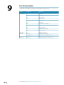
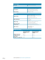
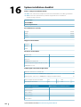
Radio frequency radiation
Harmful effects (particularly to the eyes) may be caused by exposure of any part of the
human body to high power radio frequency radiation.
Hazard distances are given in the following table:
Configuration
Distance 100 W/m
2
point (m)
Distance 50 W/m
2
point (m)
Distance 10 W/m
2
point (m)
12 kW Transceiver +
6 ft. antenna
- 0.05 0.9
The system is however designed to always disable the microwave radiation when the
antenna is not rotating.
X-Ray radiation
This radar system does not generate X-ray radiation.
Trademarks
Simrad
®
is used by license from Kongsberg.
NMEA
®
and NMEA 2000
®
are registered trademarks of the National Marine Electronics
Association.
SD
™
and microSD
™
are trademarks or registered trademarks of SD-3C, LLC in the United
States, other countries or both.
Preface | R3016 12U/6X Config. & Maint. Manual
5

Contents
8 Introduction
8
R3016 12U/6X Radar system
8 System components
9 R3016 12U/6X manuals
10 User interface
10 Main panel
11 Software setup
11 Commissioning
11 Access control
12 Setting up external sensors
14 Radar settings
18 Own ship
18 General settings of the system
20 Functional description
21 Servicing
21 Software updates
21 Back up the system
21 Tools required
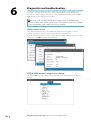
22 Diagnostics and troubleshooting
22 Radar status menu
22 NMEA 2000 network diagnostics dialog
23 Diagnostic LEDs on power supply unit
24 Diagnostic LEDs inside transceiver
24 Diagnostic LEDs on the brushless motor controller
25 Main possible failures
27 Preventative maintenance
27 External inspection of the 12U/6X X-BAND unit
27 Internal inspection of the 12U/6X X-BAND unit
28 Magnetron replacement of the 12U/6X X-BAND unit
31 Magnetron timer reset
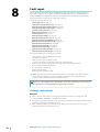
32 Fault repair
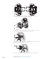
32 Antenna replacement
33 Opening and closing of the transceiver cover
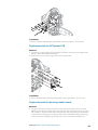
33 Replacement of the motor or gearbox assembly
34 Replacement of the brushless motor controller
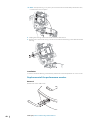
35 Electronics assembly replacement
37 Replacement of the magnetron
37 RF head replacement
38 Replacement of the RF amplifier
38 Replacement of limiter and noise diode
38 Replacement of circulator or monitor diode
39 Replacement of the SRT LAN and Mini PSU PCBs
40 Replacement of the SRT control PCB
40 Replacement of the SRT MOS PCB
41 Replacement of the SRT power PCB
41 Replacement of the bearing reader board
42 Replacement of the performance monitor
6
Contents | R3016 12U/6X Config. & Maint. Manual


Introduction
R3016 12U/6X Radar system
The R3016 12U/6X Radar system is a type approved radar system conforming to the
International Maritime Organization (IMO) requirements for vessels that are subject to SOLAS
regulations.
The system consists of:
• R3016 Control unit
• 12kW up-mast transceiver with 6ft. antenna
• R3000 Power supply unit
The radar assists in safe navigation and in avoiding collision by providing an indication, in
relation to own ship, of the position of other surface craft, obstructions and hazards,
navigation objects and shorelines. For this purpose, the radar provides the integration and
display of radar video, target tracking information, positional data derived from own ship’s
position and geo-referenced data.
To be able to provide consistent data, the R3016 12U/6X Radar system is designed to be
integrated using serial interfaces with other electronic equipment normally present in a
vessel bridge:
• Gyro-compass or transmitting heading device (HDG)
• Speed and Distance Measuring Equipment (SDME)
• Electronic Position Fixing System (EPFS)
• Automatic Identification System (AIS)
• Bridge Alert Management system (BAM)
The R3016 12U/6X Radar system is a Category 3 type approved system, approved only in the
configuration specified in the certificate. The type approval certificates are available at the
product web site: www.navico.com/commercial.
System components
The R3016 Control unit
The R3016 Control unit includes 3 main components: a processor, a monitor and a keypad.
The processor is made of a dual core CPU that integrates information coming from the
transceiver and the external sensors.
The monitor is a non-touch monitor type approved for Category 3 Radar use.
The keypad is the main control device for the system. The system cursor is controlled by the
directional pad, while several options are provided to activate radar functionalities and
navigate menus during operation.
The R3016 Control unit is fitted with an SD card reader used for updating the software and
for transferring data from the system.
The control unit is directly linked with the transceiver using a dedicated signal cable (15, 30
or 65 m length).
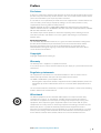
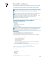
The up-mast radar sensor
The up-mast radar sensor comprises two main parts: a 6 foot antenna and a 12 kW
transceiver.
The antenna is a 6 foot X-band antenna, fixed to the transceiver unit with 4 bolts.
The transceiver is the system radio transmitter and receiver, measuring the radar echo
received from the pulse transmission. The transceiver includes a processing unit that
eliminates unwanted echoes or noise, and transfers digitized video data to the control unit.
On the back of the unit there is a safety switch and 3 connectors: Signal connector, Main
power connector, and a connector for the optional Heater kit.
+
_
1
8
Introduction | R3016 12U/6X Config. & Maint. Manual

The R3000 Power supply unit
System nominal input is 24 VDC. The power supply unit converts the available 24 VDC power
source up to the transceiver's operating voltage. The transceiver input voltage is higher to
minimize the effect of voltage drop due to cable length.
Output power cables are available in 15, 30 and 65 m lengths.
The Heater kit
The optional Heater kit is used when installing the heater in the transceiver. The heater
warms up the radar transceiver to ensure safe start-up and operation. The main components
of the Heater kit are:
• the R3000 Power supply unit - provides the additional output required to drive heater
element
• the Heater upgrade kit - all the parts that are to be included in the transceiver unit
• the cable - connects the R3000 Power supply unit to the transceiver heater power
connector
Power cables for connection between R3000 Power supply unit and Heater kit are available
in 15, 30 and 65 m lengths.
SI80 Signal Interface unit
The optional SI80 Signal Interface unit is used to provide an additional IEC 61162-2 port.
Connection to the R3016 Control unit is made via NMEA 2000. The SI80 provides power and
termination for the backbone.
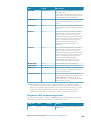
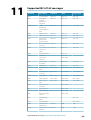
R3016 12U/6X manuals
The following documentation is delivered with the R3016 12U/6X Radar system:
R3016 12U/6X Operator manual (988-10911-00n)
User descriptions of the radar and of the features included in the system.
Intended audience: System operator.
R2009/R3016 Quick Guide (988-10951-00n)
Graphical document describing the keys and the main functions.
Intended audience: System operator.
R3016 12U/6X Installation and System wiring manual (988-10912-00n)
Mechanical installation and wiring, technical specifications and mechanical drawings for all
system components.
Intended audience: Shipyard installation personnel.
R3016 12U/6X Configuration and maintenance manual (988-10913-00n)
System setup/configuration, commissioning, trouble shooting, maintenance procedures,
replacement procedures for replaceable parts and spare parts listing.
Intended audience: Installation and service engineers.
R3016 Control unit Mounting template (988-10917-00n)
1:1 cut-out template with dimensions.
Ú
Note: The last digit in the part numbers is the document's revision code. The latest
version of all documents can be downloaded from the product website on
www.navico.com/commercial.
POWER
Introduction | R3016 12U/6X Config. & Maint. Manual
9

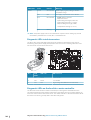
User interface
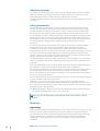
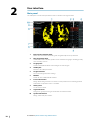
Main panel
The main panel is divided into predefined areas as shown in the figure below.
1 Plan Position Indicator (PPI)
Radar video area where all tracking and navigation options are performed.
2 Own ship information
Stabilization mode indicator, picture freeze indicator and gauges showing primary
and secondary sensors.
3 Target panel
Detailed information about selected targets and AIS targets.
4 Softkey bar
Reference for softkey functions.
5 Target indicators
Overview of target indicator settings.
6 Markers
Details for active VRM and EBL markers.
7 Cursor information
Range and bearing from the vessel to the cursor position. Also including position
information if a position source is available.
8 Alerts panel
List of all active alerts.
9 Signal indicators
Gauges for signal processing and indicators for radar functions.
10 System information
Range, mode and pulse details.
2
10
User interface | R3016 12U/6X Config. & Maint. Manual

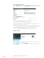
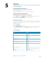
Software setup
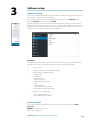
Commissioning
Prior to use, the R3016 12U/6X Radar system requires a number of settings be configured in
order for the system to perform as expected.
Access to the required menus for commissioning can be found in the Settings dialog.
Open the Settings dialog from the main Menu.
The Settings dialog consists of numerous parameters that will seldom require adjustment
beyond initial setup. All settings are stored in non-volatile memory. Most are intended to be
configured by the technician commissioning the system, by the operator at first use, or by a
technician after servicing or replacement of system parts.
Overview
The following areas must all be addressed during commissioning, and should be stepped
through one at a time, referring to the detailed sections for further information:
1 Access control
2 Setting up external sensors (Network dialog)
3 Radar settings (Installation dialog)
• Radar source
• Radar status
• Antenna setup
• Adjust range offset
• Adjust bearing alignment
• Tune
• Sector Blanking
• Auto coarse tune Adjustment
• Performance monitor adjustment
4 Own ship - vessel properties
• Reset Magnetron Timers
• Reset radar to factory defaults
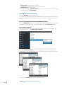
Access control
To start the commissioning process, open the Access control dialog and select Enter
password.
QWERTY is the service password.
When you are logged in:
3
Software setup | R3016 12U/6X Config. & Maint. Manual
11

• Service mode should show a tick next to it.
• All previously greyed-out menu items are now accessible.
• Service mode does not time out.
• The unit will go back to Operator mode if the user exits from the Settings dialog, or if the
user manually unticks Service mode.
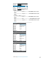
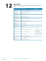
Setting up external sensors
Access the Network dialog to setup sensors.
The sensors interface to the display via the NMEA 0183 ports, either directly to the display, or
via an optional SI80 interface. The baud rate for all ports must be set to suit the connected
sensor.
Sensors connected to the control unit NMEA 0183 ports
Access the NMEA 0183 dialog, and select appropriate NMEA 0183 baud rate settings for the
connected sensors for AIS, SDME, THD, EPFS, and BAM, etc. in the Serial ports dialog.
Serial output sentences
There are three possible configurations that define what sentences are transmitted and
received by each port. Select Serial output sentences.
Then in the Sentence setup dialog select a Configuration type. The ports support the
indicated data. Selected Configuration type must match the physical connection of sensors.
Then access the Sources dialog and assign the data sources.
12
Software setup | R3016 12U/6X Config. & Maint. Manual

For BAM configuration:
• EPFS is selected under the Position option. Select R3016 NMEA 0 183 Port 1 [This
device]
• GYRO is selected under the Compass option. Select R0316 NMEA 0183 Port 4 [This
device]
For Standard and Legacy configurations:
• EPFS is selected under the Position option. Select R3016 NMEA 0 183 Port 1 [This
device]
• SDME is selected under the Boat speed option. Select R3016 NMEA 0183 Port 4 [This
device]
• GYRO is selected under the Compass option. Select R0316 NMEA 0183 Port 4 [This
device]
Ú
Note: AIS and BAM inputs do not require any configuration.
Software setup | R3016 12U/6X Config. & Maint. Manual
13

Sensor connected to the SI80
Access the Device list, select the device listed as SI80 - x (where x
equals the physical port
sensor is connected to), then select the Configure option. The SDME is connected to the
SI80.
Select appropriate NMEA 0183 settings for the connected sensors:
• Baud rate: set the baud rate to suit the connected sensor.
Then access the Sources dialog and select the NMEA 2000 device which will supply the
required data. In this case the port on the SI80.
Ú
Note: The SI80’s port can be assigned a more meaningful name when viewing the
Device Information page for the port. It is recommended that the default port name be
appended with a description of sensor type, for example, SI80-3 SDME.
Ú
Note: See the "Supported IEC 61162 messages" on page 49 for supported sentences.
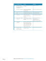
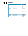
Radar settings
Radar installation
The radar system requires scanner specific adjustments to be made in order to adjust for a
number of variables found in different installations.
Access the Radar menu, and choose Installation, then configure the settings under the
following headings.
14
Software setup | R3016 12U/6X Config. & Maint. Manual

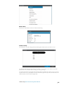
Radar status
Primarily for information and to assist with fault finding.
Antenna setup
This function is used for setting position and height of radar transceiver on the vessel.
The approximate position of the transceiver on the vessel must be set in order to correctly
position the vessel outline when viewing close range settings.
The antenna height is the height of the antenna above the water line, when vessel is carrying
a typical load. It is very important to set the antenna height correctly as this will affect the sea
clutter function. Do not set the height to 0.
Software setup | R3016 12U/6X Config. & Maint. Manual
15

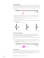
Adjust range offset
The radar sweep should commence at your vessel (a radar range of zero). You may need to
adjust the radar range offset to achieve this. If this is set incorrectly, a large dark circle in the
center of the sweep might occur. You might notice straight objects such as straight sea walls
or piers having curves or an indentation. Objects close to your vessel may appear “pulled in”
or “pushed out”.
Adjust the range offset as below when the vessel is about 45 to 90 m (50 to 100 yards) from a
straight-walled jetty or similar feature that produces a straight line echo on the display.
• Point the boat towards the jetty
• Adjust the gain setting until a reasonably good image of the jetty echo is displayed
With the Range offset dialog open:
• Turn the rotary knob to adjust the range offset to make the jetty echo appear as a straight
line on the display
• Press the ENT key to save the settings
X X
Adjust bearing alignment
This is to align the heading marker on the screen with the center line of the vessel. This
setting compensates for any slight misalignment of the up-mast transceiver during
installation. Misalignment that is not corrected for will compromise target tracking and can
result in dangerous misinterpretation of potential navigation hazards.
Point the vessel towards a stationary isolated object. Then with the Bearing alignment dialog
open:
• Press the rotary knob to switch focus between coarse and fine bearing alignment
• Turn the rotary knob to adjust the bearing alignment so that the heading line touches the
end of the selected stationary object
• Press the ENT key to save the settings and close the Bearing alignment dialog
Sector blanking
To assure passenger safety from radiation and if the radar is installed in close proximity to a
mast or structure, that could cause unwanted reflections or interference to appear on the
radar image, use the sector blanking feature to stop the radar from transmitting in a defined
direction, over a variable sector size. Up to four sectors can be set up.
16
Software setup | R3016 12U/6X Config. & Maint. Manual

Ú
Note: Sectors are setup relative to the heading line of the radar. The bearing of the
sector is measured from the front of the vessel to the center line of the sector.
Tune
The Tune option is used to do initial manual tuning of the radar system and to adjust the
radar when a new magnetron has been fitted.
Set the range scale at 24 NM, the tuning control in manual and centered at 50.
With the Tune dialog open:
• Turn the rotary knob to adjust the coarse tune value until the best reflection is obtained
• Press the ENT key to save the settings and close the Tune dialog
Auto coarse tune adjustment
The Auto coarse tune adjustment is used to do initial automatic tuning of the radar system
and to adjust the radar when a new magnetron has been fitted.
Set the range scale at 24 NM, the tuning control in manual and centered at 50.
When the the Auto coarse tune adjustment is selected, a progress bar indicates status. The
coarse value is stored automatically when the tuning is completed.
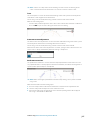
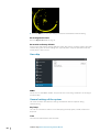
Performance monitor
The performance monitor is used to check the output performance of the transceiver. It is
very important that it is initially adjusted at time of installation, and when the magnetron is
replaced, when power output is still optimal.
Ú
Note: Before entering the performance monitor setup dialog, set to system to 24 NM
range scale.
With the Performance monitor dialog open:
1. Press the rotary knob to switch focus between the on/off icon the adjustment icon
2. Turn the rotary knob to adjust the value of the active icon
3. Activate the Adjust icon and adjust the value until the opening with of the displayed
noise ring is around 60° to 100° width
Software setup | R3016 12U/6X Config. & Maint. Manual
17

4. Press the ENT key to save the settings and close the Performance monitor dialog
Reset magnetron timers
Refer to "Magnetron timer reset" on page 31.
Reset radar to factory defaults
Clears all user and installer settings applied to radar, and restores ex-factory settings. Use with
caution, taking note of current settings first, especially those set by the operator if radar has
already been in active service.
Own ship
MMSI
Set the vessel’s own MMSI number. This prevents the vessel being identified as an AIS target
on own display.
General settings of the system
This menu contains miscellaneous settings and functions that are required during
commissioning.
Key beeps
You can set one of three loudness levels of beeping for beeps (quiet, normal, loud) or turn
beeps off.
Time
Set local time and formats of time and date.
18
Software setup | R3016 12U/6X Config. & Maint. Manual

Restore defaults
Clears all user adjustments to the radar, but maintains settings applied by the installer.
Files
This menu is used to browse the contents of an inserted SD card, primarily for the purpose of
installing updates to the system software, and to allow the saving of system configuration
back-ups.
Perform a backup once all other commissioning steps have been completed.
Software setup | R3016 12U/6X Config. & Maint. Manual
19

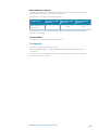
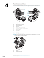
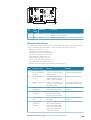
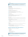
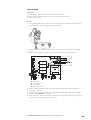
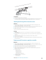
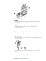
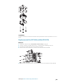
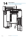
Functional description
The drawing below represents the general view of the main components that are described
in detail in other sections of this manual. This drawing serves as a reference for the location of
these parts.
1
7
8
9
10
3
2
4
5
6
1 Magnetron
2 Magnetron HT connection
3 Bearing reader board
4 MOS PCB
5 Brushless motor controller PCB
6 Performance monitor connection point
7 Antenna platform
8 Control PCB
9 Power PCB
10 Motor & gearbox assembly
Ú
Note: The mini power supply system and SRT LAN PCBs are not shown here, as they are
concealed within the electronics assembly.
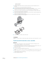
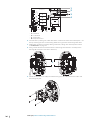
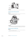
1
2
1 RF head
2 Electronics assembly
4
20
Functional description | R3016 12U/6X Config. & Maint. Manual
Page is loading ...
Page is loading ...
Page is loading ...
Page is loading ...
Page is loading ...
Page is loading ...
Page is loading ...
Page is loading ...
Page is loading ...
Page is loading ...
Page is loading ...
Page is loading ...
Page is loading ...
Page is loading ...
Page is loading ...
Page is loading ...
Page is loading ...
Page is loading ...
Page is loading ...
Page is loading ...
Page is loading ...
Page is loading ...
Page is loading ...
Page is loading ...
Page is loading ...
Page is loading ...
Page is loading ...
Page is loading ...
Page is loading ...
Page is loading ...
Page is loading ...
Page is loading ...
Page is loading ...
Page is loading ...
Page is loading ...
Page is loading ...
-
 1
1
-
 2
2
-
 3
3
-
 4
4
-
 5
5
-
 6
6
-
 7
7
-
 8
8
-
 9
9
-
 10
10
-
 11
11
-
 12
12
-
 13
13
-
 14
14
-
 15
15
-
 16
16
-
 17
17
-
 18
18
-
 19
19
-
 20
20
-
 21
21
-
 22
22
-
 23
23
-
 24
24
-
 25
25
-
 26
26
-
 27
27
-
 28
28
-
 29
29
-
 30
30
-
 31
31
-
 32
32
-
 33
33
-
 34
34
-
 35
35
-
 36
36
-
 37
37
-
 38
38
-
 39
39
-
 40
40
-
 41
41
-
 42
42
-
 43
43
-
 44
44
-
 45
45
-
 46
46
-
 47
47
-
 48
48
-
 49
49
-
 50
50
-
 51
51
-
 52
52
-
 53
53
-
 54
54
-
 55
55
-
 56
56


Simrad R3016 12U/6X Operating instructions
- Type
- Operating instructions
Ask a question and I''ll find the answer in the document
Finding information in a document is now easier with AI
Related papers
-
Simrad R3016 12U/6X Installation guide
-
-
-
-
-
-
-
-
 Navico I3005/I3007 User manual
-

Other documents
-
Ryobi PSBCK05K2 Owner's manual
-
-
Widex Compass GPS 4.6 User guide
-
-
-
-
Duracell DL1/3N User manual
-
Digimerge ACCHTR01 User manual
-
Raytheon Standard 30 MF 110-700 Edition November 2020 Operating instructions
-
 MARINE DATA F069036 User manual
