Page is loading ...

USER MANUAL MD69BRX
F069036 – UNIVERSAL MOUNT COMPASS
BEARING REPEATER FOR RETROFIT
MD69BR-MA-v06r01
2019-11-19
ENGLISH


MD69BRX
3
CONTENTS
1 MD69BRX BEARING COMPASS REPEATER ................................... 5
2 DOCUMENT ....................................................................................... 6
2.1 About This Manual .......................................................................................... 6
3 NOTICE .............................................................................................. 7
3.1 Copyright ......................................................................................................... 7
4 DESCRIPTION ................................................................................... 8
5 PRINCIPLE OF OPERATION ............................................................. 9
6 APPLICATION.................................................................................. 10
6.1 Data Sentences ............................................................................................. 10
7 SPECIAL FEATURES ...................................................................... 10
8 MAJOR DIMENSIONS...................................................................... 11
8.1 MD69BRX/B1 Retrofitting Kit Dimensions .................................................... 11
8.2 MD69BRX/P1 & P2 Retrofitting Kit Dimensions ........................................... 12
9 INSTALLATION ................................................................................ 13
9.1 Parts List ........................................................................................................ 13
9.2 Fitting the Unit ............................................................................................... 13
9.3 Pin Connections (by function) ....................................................................... 14
9.4 Typical Connection Diagram ......................................................................... 15
10 COMMISSIONING THE PRODUCT .................................................. 16
10.1 Product Registration ...................................................................................... 16
11 OPERATION .................................................................................... 17
11.1 Operator Controls and Indicators .................................................................. 17
11.2 Normal Operation .......................................................................................... 18
11.3 Illumination Control........................................................................................ 18
11.4 Heading Type Indication ............................................................................... 18
11.5 Loss of Data Indication .................................................................................. 18
11.6 Automatic Baud Rate Detection .................................................................... 18
11.7 Azimuth Sight Operation (optional accessory) ............................................. 19
11.7.1 Taking Bearings: ............................................................................... 19
Terrestrial Bearings ....................................................................................... 19
Celestial Bearings ......................................................................................... 19
12 MAINTENANCE & FAULT FINDING ................................................ 20
12.1 Maintenance .................................................................................................. 20
12.2 Fault-Finding .................................................................................................. 20
12.2.1 MD69BR does not operate ............................................................... 20

MD69BRX
4
12.2.2 MD69BR aligns to zero degrees but does not follow the source
heading .............................................................................................. 20
12.2.3 Display Illumination not functioning ................................................... 20
12.2.4 Dial oscillating +/- 35 degrees ........................................................... 20
12.3 Technical Support .......................................................................................... 21
12.4 Reporting a Fault ............................................................................................ 21
13 SPECIFICATIONS ............................................................................ 22
13.1 Physical .......................................................................................................... 22
13.2 Electrical ......................................................................................................... 22
13.3 Operational ..................................................................................................... 22
13.4 Environmental ................................................................................................ 23
13.5 Additional Information .................................................................................... 23
14 SPARE PARTS & ACCESSORIES ................................................... 24
15 GROUNDING AND SHIELDING ....................................................... 26
16 SAFETY AND SECURITY ................................................................ 26
17 GLOSSARY OF TERMS ................................................................... 27
18 ABOUT MARINE DATA ................................................................... 28

MD69BRX
5
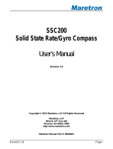
1 MD69BRX BEARING COMPASS REPEATER
MD69BRX Bowl:
• Dual Scale concentric dials
• Outer Verge Ring
• Heading Type Indicators
• Local Dimming Knob
MD69BRX top view
MD69BRX bottom view

MD69BRX
6
2 DOCUMENT
2.1 About This Manual
This Manual provides installation, operating Instructions and fault-finding procedures for the
Marine Data MD69BRX Bearing Compass Repeater for retrofit.
After installation, this manual should remain with the vessel to which it relates.
This manual may also be made available in electronic Portable Document Format (PDF). In PDF
format, the following categories are all enabled as active hyperlink references: (1) The titles of
each section; (2) document cross-references; (3) the table of contents.
This document may therefore be navigated quickly and effectively by using a mouse or other
pointing device to activate each of these hyperlinks. This is a printer friendly document, designed
to be printed 2-sided as a booklet with A5 pages on A4 stock paper.
An electronic Portable Document Format (PDF) of this manual is also available for download from
the support section of our website: marine-data.co.uk/support/product-manuals.
Document name
Date:
Details:
Author:
MD69BRX-MA-v05r01
2018-12-26
First Issue
TSI
MD69BRX-MA-v06r01
2019-11-19
Multiple changes across whole document
TSI / PJY

MD69BRX
7
3 NOTICE
3.1 Copyright
The copyright and all rights of a like nature in respect of this publication in any part of the world
are the property of Marine Data Systems Ltd. (Marine Data).
No part of this document may be reproduced or transmitted in any form or by any means, whether
electronic, mechanical, photocopying, recording or otherwise, nor stored in any information
retrieval system of any kind, nor used for tendering or manufacturing, nor communicated to any
other person without the written permission of Marine Data.
The recipient of this document, as its registered holder, must exercise due diligence in ensuring
that the above conditions are observed (Errors and Omissions Excepted).
Any enquiries relating to this document or its contents should be addressed, in writing, in the first
instance to Marine Data.
MARINE DATA SYSTEMS LIMITED
Vittlefields Technology Centre
Forest Road
NEWPORT
Isle of Wight
PO30 4LY
UNITED KINGDOM
tel: +44 (0)1983 822180
email:
sales@marine-data.co.uk
Marine Data Systems Limited reserves the right to make changes to its products and
specifications without notice

MD69BRX
8
4 DESCRIPTION
The MD69BRX is a Dual Scale Dial Type Bearing Compass Repeater, provided as a bowl-only
option for retrofit or replacement into third party gimbal rings. It is designed to display Ships
Heading as part of a Gyro-Compass or Transmitting Magnetic Compass system. It receives data
via a NMEA 0183 type digital transmission.
The Primary function of the MD69BRX is to display Ship’s Heading from a Gyro Compass (or
other source of Heading) and provide a facility for taking Celestial or Terrestrial Bearings from the
ship. It has a 185 mm diameter outer dial marked in 1 degree increments with numeric values
every 10 degrees plus cardinal and inter-cardinal markers. The outer dial rotates one revolution
for 360 degrees. It also has a 95 mm diameter inner dial marked in 0.1 degree increments with
numeric values every 1 degree. The inner dial rotates one revolution for 10 degrees, i.e. 36 times
for every single revolution of the outer dial. A lubber-line is provided to allow the heading indicated
by the dial to be read accurately.
The dials are illuminated for easy reading and dimmable to allow the repeater to be viewed in any
lighting condition from full sunlight to total darkness. The illumination level is adjustable down to
zero so that night vision is not affected. Dimming can be controlled either by the rotary control
mounted on the repeater bowl or by a remote dimmer.
The MD69BRX has two indicator LEDs mounted in the outer verge-ring on either side of the
lubber-line position to show the heading type in use (True or Magnetic).
The MD69BRX Bearing Compass Repeater is normally supplied with either a Gimbal Bearing or
Gimbal Pins Retrofitting Kit. We provide a range of options to fit into third-party gimbals, see the
product dimensions section for more information.
The Repeater is counterbalanced to allow it to remain in a horizontal position whilst being read,
however flush panel mounting is also available as an option.
Constructed in a robust, waterproof, aluminium enclosure and finished in RAL7040 Window Grey
paint, the MD69BRX will complement existing marine navigation equipment.
The MD69BRX a Dual Scale Dial Type Bearing Compass Repeater from Marine Data: Designed
to be easy to install and simple to maintain.

MD69BRX
9
5 PRINCIPLE OF OPERATION
The Repeater accepts serial heading data from a Gyro-Compass or Transmitting Magnetic
Compass in digital format using standard NMEA 0183 (IEC61162-1) True or Magnetic sentence.
The input is processed by electronic circuitry contained within the Repeater enclosure. Powered
from 18 V to 32 V dc derived from the ships supply, power consumption is low - typically less than
4 watts.
An embedded micro-controller processes the received heading information and in turn drives a
stepper motor connected to the dial. On application of power, the dial is rotated to align to a zero-
reference position controlled by an optical switch. Subsequently, on reception of valid data, the
dial is driven to display the received heading. When updated heading information is transmitted
to the Repeater, the dial will then follow this new heading.
Sophisticated firmware embedded in the micro-controller monitors the received data, user
controls and other control signals and provides control of dial illumination, and indicators.
Suppression circuitry and opto-isolation are used to provide over voltage and reverse polarity
protection as well as compliance to EMC and data transmission standards.

MD69BRX
10
6 APPLICATION
The MD69BRX displays True or Magnetic Heading Data transmitted from NMEA 0183 (IEC
61162-1) compatible marine equipment (Gyro-Compass, TMC, GPS Compass etc.)
6.1 Data Sentences
The following NMEA 0183 sentences (in priority order) may be used to display Heading:
• THS: ( $--THS, x.x, S*hh<CR><LF> ) Heading True with Status
(S = Status = “A”)
• HDT: ( $--HDT, x.x, T*hh<CR><LF> ) Heading True
(True Heading Data)
• HDG: ( $--HDG, x.x, x.x, a, x.x, a*hh<CR><LF> ) Heading True (from Magnetic)
(Heading Data corrected for the Earth’s Magnetic Variation and the vessel’s Deviation)
• HDG: ( $--HDG, x.x,,,,*hh<CR><LF> ) Heading Magnetic
(Heading Data not corrected for the Earth’s Magnetic Variation and the vessel’s Deviation)
• HDM: ( $--HDM, x.x, M*hh<CR><LF> ) Heading Magnetic
(Heading Data not corrected for the Earth’s Magnetic Variation or the vessel’s Deviation)
7 SPECIAL FEATURES
• Dual Scale dial type display of Heading, readable to < 0.1°
• Designed for taking Terrestrial or Celestial Bearings (with Azimuth Sight)
• NMEA 0183 input with Automatic Baud Rate selection
• Automatic Prioritisation of Heading type:
o THS / HDT (True)
o HDG (Magnetic + Variation),
o HDG (Magnetic, No Variation),
o HDM (Magnetic)
• Automatic Switching to lower priority Heading Type (if available) on loss of data
• User indication of loss of all valid Heading Data
• Local and/or Remote dimming control

MD69BRX
11
8 MAJOR DIMENSIONS
8.1 MD69BRX/B1 Retrofitting Kit Dimensions

MD69BRX
12
8.2 MD69BRX/P1 & P2 Retrofitting Kit Dimensions
274

MD69BRX
13
9 INSTALLATION
Check that the delivered item supports user requirements (contact your local distributor in the
event of any uncertainty or discrepancy). Note any damaged or missing items. Determine whether
a surface mounting option (with bracket and gimbal) or a flush panel mounting option is to be
used and ensure that the correct parts are included for your application.
CAUTION: When unpacking the Bearing Repeater, if the package is opened upside
down then the weighted bowl of the Repeater will attempt to right itself. Please keep
hands and fingers clear.
9.1 Parts List
Item:
Description:
No.
included:
Marine Data
Part Number:
1
MD69BRX – Compass Bearing Repeater bowl
1
F069018
2
MD69BRX/B1 – Bearings Mount
(2) Option
F069303
3
MD69BRX/P1 – Pins Mount
(2) Option
F069301
4
MD69BRX/P2 – Pins Mount
(2) Option
F069302
9.2 Fitting the Unit
1. Inspect the mounting position for suitable clearance and cable access. For mounting
dimensions, refer to section 8 MAJOR DIMENSIONS.
2. Secure the MD69BRX in place with the chosen mounting options.
3. Review the system cable conductors and their function.
4. Identify the vessel’s wiring functions. It is recommended that a note be made of the vessel’s
wiring functions for future reference. Connect the MD69BRX in accordance with table 9.3
Pin Connections (by function).
5. The MD69BRX is designed to use 24 V dc and accept a digital RS422 data signal using the
NMEA 0183 protocol. Ensure all incoming supply and signal cables are either: suitably
insulated and/or connected, or bonded to the vessel’s earth where appropriate.
6. Isolation and Earth requirements must comply with Lloyd’s Rules and Regulations VI,
paragraph 1.13.2
7. Do not apply power yet.
CAUTION: Application of any voltage other than those stipulated in this product
specification may damage the compass repeater.

MD69BRX
14
9.3 Pin Connections (by function)
Term:
Type:
Function:
Description:
Core
colour1:
1
Input
Positive
+ dc Supply (12 / 24 V Nominal)
RD
2
Input
Negative
Supply Return
WH
3
Input
0-24 V
Dimmer
Optional External Dimmer Input. 0 V = Minimum
Illumination; 24 V = Maximum Illumination
(Isolate or connect to supply negative if not used)
PK
4
-
-
Do Not Connect
(Isolate or connect to ground if not used)
BN
5
Input
RDA
NMEA 0183 (IEC 61162-1) Data Input A
GN
6
Input
RDB
NMEA 0183 (IEC 61162-1) Data Input B
BU
7
Output
TDA
NMEA 0183 (IEC 61162-1) Data Output A (Isolate if
not used)
GY
8
Output
TDB
NMEA 0183 (IEC 61162-1) Data Output B (Isolate if
not used)
YE
Earth
Chassis
Chassis
Connection
Screen
SCN
1
IEC 60757 colour abbreviations

MD69BRX
15
9.4 Typical Connection Diagram

MD69BRX
16
10 COMMISSIONING THE PRODUCT
Ensure that the installation complies with section 9 INSTALLATION.
Apply system power (24 V dc) to the MD69BR.
The MD69BR will initially align to zero degrees; it will then adopt the heading which is being
transmitted from the heading source.
Verify that the MD69BR follows the heading source when altering the vessel’s heading.
If an error condition arises, refer to section 11.5 Loss of Data Indication.
Ensure that the background display lighting is set to a suitable level using the integral rotary
dimmer control or a remote dimmer if connected.
Be sure to fill out the product registration form and return it to Marine Data. This activates the
warranty.
10.1 Product Registration
Be sure to register your product online at www.marine-data.co.uk.
You will need:
• Product Type (e.g. MD69BRX)
• Product Serial No.
• Vessel on which the product is installed
• Installation Date
• Installer / Customer representative contact details
It would also be helpful to list other manufacturer’s equipment to which the product is connected
(e.g. Gyro, Radar, other Repeaters etc).
Alternatively, fill out a product registration form and return it to Marine Data.
NOTE: It is the process of registration which activates the warranty.

MD69BRX
17
11 OPERATION
11.1 Operator Controls and Indicators
Rotary
Dimmer
Control
Lubber Line
True Heading
Type Indicator
(Blue)
Magnetic Heading Type
Indicator (Yellow)
360° Outer Dial
10° Inner Dial
(36:1 ratio)
Verge Ring
(fixed)

MD69BRX
18
11.2 Normal Operation
In normal operation, the TRUE HEADING indicator (blue) and the MAGNETIC HEADING indicator
(yellow) are used to show the type of heading displayed.
If True Heading is being displayed then the TRUE HEADING indicator will be illuminated. If
Magnetic Heading is being displayed then the MAGNETIC HEADING indicator will be illuminated.
11.3 Illumination Control
The illumination level of the dials and indicators are adjusted using the rotary dimmer control
mounted in the repeater bowl or by an external remote dimmer connection.
The bowl mounted dimmer control includes a push button function (press the control knob) which
is used for Alert Acknowledge and Self Test functions,
Note: At the minimum illumination level, the dial illumination is fully extinguished. However, active
indicators remain lit at a very low level to allow reading of the indicators in total darkness.
11.4 Heading Type Indication
The type of heading being displayed depends on the received data. The respective TRUE
HEADING or MAGNETIC HEADING indicator will illuminate to indicate the type of heading being
displayed. If both heading types are available, the dial will default to TRUE.
11.5 Loss of Data Indication
The MD69BR repeater should be refreshed with data at least three times a second. If no valid
data is received, MD69BR will indicate this to the user by rotating the dial ±35° about the last
known valid heading.
11.6 Automatic Baud Rate Detection
If valid data is not received, then the MD69BRX will scan all available Baud rates to look for valid
data at an alternative rate. If valid data corresponding to the list of acceptable data sentences is
found, then the Baud rate of that data will be stored and used for future data reception. With this
feature there is no requirement to pre-select a Baud rate for data transmission.

MD69BRX
19
11.7 Azimuth Sight Operation (optional accessory)
The MARINE DATA MD69AZI Azimuth Sight (Thomson Pattern) meets the International Standard
ISO 25862:2009 for the testing and certification of Group II Azimuth reading devices.
CAUTION: Always use Sun filters when taking azimuth bearings of the Sun; never
attempt to take bearings of the Sun with unprotected eyes.
11.7.1 Taking Bearings:
Terrestrial Bearings
For taking bearings of landmarks or objects with low luminosity (the arrow on the prism adjustment
thumbwheels = DOWN). A distant object is sighted directly by eye with the compass card being
simultaneously viewed indirectly through the prism. Maximum altitude 34° above the horizon.
Celestial Bearings
For taking bearings of the Sun or other celestial objects (the arrows on the prism adjustment
thumbwheels = UP). The compass card is viewed directly through the collimating lens, with a
distant object being simultaneously viewed indirectly through the reflecting prism. Maximum
altitude 60° above the horizon.

MD69BRX
20
12 MAINTENANCE & FAULT FINDING
12.1 Maintenance
No scheduled maintenance is required. It is recommended to gently wipe away any accumulated
dust periodically with a soft lint free cloth.
Note: The MD69BR is a sealed unit and has no user-serviceable parts inside. Breaking
the factory seal will invalidate the warranty.
12.2 Fault-Finding
12.2.1 MD69BR does not operate
It is probable that there is a loss of power. Check the dc power supply and data connection to the
unit.
12.2.2 MD69BR aligns to zero degrees but does not follow the source heading
The NMEA 0183 digital signal to the repeater is either not present, or the data sentence being
sent is not of the correct structure. Check the heading source data for the presence of a valid
heading data sentence; refer to section 11.5 Loss of Data Indication for details of indication in the
case of no data.
12.2.3 Display Illumination not functioning
If remotely controlled, an incorrect control signal may be being received, check wiring and signals.
The internal LED illumination devices may be damaged or there may be damage to the PCB or
rotary dimmer switch. Return the unit to Marine Data for servicing. It should be noted that the
display illumination may not be noticeable under bright ambient light conditions. Illumination is
controlled independently by the integral rotary dimmer control and the Remote Dimmer input, if
fitted, whichever input is adjusted will take precedence.
12.2.4 Dial oscillating +/- 35 degrees
Check NMEA data connection and validity. Refer to section 11.5 Loss of Data Indication for details
of indication in the case of no data.
/