Page is loading ...

Quick-Flip™ III - Electric
P/N 1808684 Rev. I

Shur-Co
®
, LLC Terms & Conditions
PREPAID FREIGHT POLICY. Shur-Co
®
, LLC
will prepay freight on eligible orders* of Florida-manufactured
Donovan products and tarp items shipped from our FL and MI branches that
meet the dollar requirements for the shipping destinations specifi ed below.
*Valid within the continental 48 states only. Applies to products purchased at standard pricing; any
special pricing will void standard prepaid freight policy and will be addressed on a case-by-case
basis. Does NOT apply to Bedliners or Shur-Co
®
Flatbed products.
INTO FL/MI: Freight prepaid on orders of $2,500 or more or tarp-only orders
of $1,500 or more. INTO ZONES 1 & 2: Freight prepaid on orders of $3,000
or more or tarp-only orders of $2,500 or more. INTO ZONES 3 & 4: Freight
prepaid on orders of $6,000 or more or tarp-only orders of $3,000 or more.
WARRANTY. We warrant all new products are free of defects in materials and
workmanship.* This warranty is effective if products are properly installed and
used for the purpose for which they were intended and applies to the original
buyer only. Except as set forth above or in any product-specifi c warranty docu-
mentation, we make no other warranties, express or implied, including but not
limited to warranties of merchantability of fi tness for a particular use.
Returns of a product for warranty must be accompanied by a Return Merchan-
dise Authorization number (RMA#), obtained by by calling Customer Service
at 800-327-8287, and sent, freight paid by us, to Donovan, 3353 SE Gran Park
Way, Stuart, FL 34997. All products returned without an RMA# will be refused.
When we issue the RMA#, we will also issue a call tag to have
U.P.S. (or other freight company) pick up the product. C.O.D. returns not
accepted. We will pay no storage fees for a warranty product return prior to
pick by us or the freight company. If a warranty product return is scheduled to
be picked up by us, we will pick up the product at our earliest convenience.
If a product returned is found, in our judgement, to be defective in material
or workmanship, our obligation under this warranty is limited to the repair or
replacement of the product, which will be made by us. Repair or replacement
will be at our discretion, with replacements being made using current products
performing in the equivalent function. Labor charges, other than those incurred
at our factory, including, but not limited to, any labor to install a repaired or re-
placement product, are not covered under this warranty. All expenses associ-
ated with delivering defective products to our factory and delivering repaired or
replacement products from our factory to the owner will be paid by us.
If the product returned is found, in our judgement, to be non-warrantable, the
owner will be contacted to authorize repair work, purchase of a replacement
product or return of the product, all of which will be at the owner’s expense.
Payment authorization must be received by us before any non-warrantable
product is repaired, replaced or returned. All expenses associated with deliver-
ing the repaired non-warrantable product, a replacement product or the non-
warrantable product from our factory to the owner will be paid by the owner.
In no event will we be liable for any damages of any kind to person, product or
property, including but not limited to indirect, incidental, special, consequential
or punitive damages, or damages for loss of profi ts or revenue, even if we
have been advised of the possibility of such damages. There are no warran-
ties for used products or products that have been repaired, altered, modifi ed
or subjected to misuse, negligence or accident. We will not repair or replace
products that fail or malfunction due to ordinary wear and tear, except as ex-
pressly noted in a product-specifi c warranty. Use of non-Shur-Co
®
, LLC parts
in conjuction with Shur-Co
®
, LLC products will void this product warranty.
*Certain products have specifi c warranties that differ from this warranty, for example motors and elec-
tronics. Product-specifi c warranty documentation is available for these items. In the event of a confl ict
between this warranty and a product-specifi c warranty, the product-specifi c warranty will govern.
RETURN POLICY. All sales fi nal. See WARRANTY above for return details.
OTHER. All prices, product listings, sizes, weights and manufacturing details
are subject to change without notice. No person is authorized to modify the
foregoing conditions of sale whatsoever.
SHUR-CO
®
, LLC SERVICE AND DISTRIBUTION CENTERS
ZONE 4
ZONE 3 ZONE 2
ZONE 1
FL
FL
M
MI
Corporate HQ and Outlet Store
SHUR-CO
®
of SOUTH DAKOTA
2309 Shur-Lok St., PO Box 713
Yankton, SD 57078-0713
Ph 800.474.8756 | Fax 605.665.0501
SHUR-CO
®
of FLORIDA
3353 SE Gran Park Way
Stuart, FL 34997
Ph 800.327.8287 | Fax 772.287.0431
SHUR-CO
®
of ILLINOIS
3993 E. Mueller Ave.
Decatur, IL 62526
Ph 866.356.0246 | Fax 217.877.8270
SHUR-CO
®
of IOWA
3839 Midway Blvd.
Ft. Dodge, IA 50501
Ph 866.356.0245 | Fax 515.576.5578
ShurTite™ Service Centers
SHUR-CO
®
of CANADA
490 Elgin St., Unit #1
Brantford, Ontario N3S 7P8
Ph 800.265.0823 | Fax 519.751.3997
SHUR-CO
®
of SIOUX FALLS
47184 258th St., Suite B
Sioux Falls, SD 57107
Ph 844.573.9322 | Fax 605.543.5469
SHUR-CO
®
of ILLINOIS
Ph 866.356.0246 | Fax 217.877.8270
SHUR-CO
®
of OHIO
Ph 866.356.0242 | Fax 330.297.5599
SHUR-CO
®
of MICHIGAN
5100 Lakeshore Dr.
Lexington, MI 48450
Ph 800.327.8287 | Fax 772.287.0431
SHUR-CO
®
of NORTH DAKOTA
1746 4th Ave. NW
West Fargo, ND 58078
Ph 877.868.4488 | Fax 701.277.1283
SHUR-CO
®
of OHIO
1100 N. Freedom, St. Rt. 88 & 14
Ravenna, OH 44266
Ph 866.356.0242 | Fax 330.297.5599
SHUR-CO
®
UK, Ltd.
Unit 41 Rochester Airport Estates
Laker Rd., Rochester, Kent ME1 3QX
Ph +44 (0)1795.473499
Fax +44 (0)871.272.8278
For more information, log on to our website:
www.donovan-tarps.com
P/N 1808684 Rev. I

Thank you for buying this tarping system from Shur-Co
®
. We appreci-
ate your condence in our products. Please read and thoroughly un-
derstand this manual before installing and/or operating this system.
Pay particular attention to important safety and operating instructions,
as well as warnings and cautions. The hazard symbol is used to
alert users to potentially hazardous conditions and is followed by cau-
tion, warning or danger messages.
Failure to READ AND FOLLOW INSTRUCTIONS could result in fail-
ure of your tarping system and/or personal injury. Your trailer require-
ments may, however, call for minor variations to these instructions.
Please inspect your tarping system periodically. Repair or replace
worn or damaged parts to your system.
QUESTIONS? CALL OUR FL HELP LINE:
1-800-327-8287
MON-FRI 8 AM-5 PM EASTERN TIME
We at Shur-Co
®
are concerned with your safety and the safety of all
those operating this system. Therefore, we have provided safety de-
cals at various locations on your tarping system. Keep decals as clean
as possible at all times. Replace any decal that has become worn
or damaged, painted over or otherwise difcult to read. Replacement
decals are available through Shur-Co
®
dealers.
To prevent rust, paint all exposed metal, such as weld seams and/or
metal exposed by grinding or cutting, with corrosion-resistant paint.
Quick-Flip™ III EL
P/N 1808684 Rev. I
!
Hardware Identication ....................................................................... 1
Clearance Requirements .................................................................... 2
Base Assembly Installation ................................................................. 2
Housing Assembly Installation ............................................................ 3
Spring Pivot Installation - Single Axle Fixed Gantry ........................4-5
Spring Pivot Installation - Tandem Axle Hydraulic Gantry ...............6-7
Spring Pivot Installation - Trailers ....................................................8-9
Pivot Arm Installation - Single Axle ................................................... 10
Pivot Arm Installation - Tandem Axle Hydraulic Gantry .................... 11
Pivot Arm Installation - Trailers ......................................................... 12
Tarp Tube Assembly & Tarp Installation ............................................13
Pre-Load Springs ..............................................................................14
Hydraulic Pump Installation .........................................................15-16
Electric Installation .......................................................................17-18
Pivot Arm Rest Installation ................................................................ 19
Replacement Parts ......................................................................20-27
1. Wrenches - 1/2”, 5/16”, 9/16”, 5/8”, 3/4”, 7/8”
2. Ratcheting Socket Wrench
3. Sockets - 1/2”, 9/16”, 3/4”
4. Allen Wrenches - 1/8”, 5/32”, 3/16”
5. Drill Bits (metal cutting) - 5/16”, 3/8”, 1/2”, 3/16”
6. Center Punch
7. Hammer
8. Tape Measure
9. Flat Head or Phillips Screwdriver
10. Grinder
11. Air or Electric Impact Driver w/9/16” Socket
12. Metal Saw
13. Steel Welder
14. Hex Driver Bit - 5/16”
15. Phillips Driver Bit - #2
• Spray all bearings and drive chain with penetrating oil as needed.
• Brush springs with steel brush weekly to remove dirt and spray with
penetrating oil.
• Tighten any loose bolts.
• Replace damaged/bent parts.
• Replace worn or broken springs.
• Replace/repair worn or damaged tarps.
TOOLS REQUIRED
TABLE OF CONTENTS
MAINTENANCE
RUST PREVENTION
SAFETY
MESSAGE TO OWNERS
1. Always wear safety glasses during installa-
tion and operation.
2. Stay clear of moving parts.
3. Do not operate under low-hung power lines.
Always check for overhead obstructions be-
fore opening or closing.
4. Open and close tarp only at job site.
5. Place safety decals in visible locations. Re-
place worn or damaged decals.
6. No other use of this system is authorized,
except as designed.
SAFETY INSTRUCTIONS

P/N 1808684 Rev. I
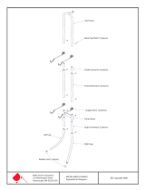
Hardware Identication
1
Tarp length: Measure tarp length with slight tension applied. Compare actual tarp length with length stated on sheet attached to tarp. If tarp
length does not match length on sheet, do not proceed. Call your local dealer or call Shur-Co
®
FL Customer Service at 1-800-327-8287.
TARP INSPECTION
1800996 Flat Washer - 1/2"
1800995 Lock Nut - 1/2"
1801024 Cap Screw - 1/2" x 4"
1800356 Carriage Bolt - 1/2" x 1 1/2"
1800994 Flat Washer - 3/8"
1804139 Cap Screw - 3/8" x 3 1/4"
1800561 Pan Hd. Cap Screw - 5/16" x 2 1/4"
1800993 Nylon Lock Nut - 3/8"
1800989 Flat Washer - 5/16"
1800990 Lock Nut - 5/16"
1800790 Cap Screw - 3/8" x 1 1/2"
1800991 Lock Washer - 3/8"
1800784 Flat Washer - 1/4"
1800802 Sheet Metal Screw - #10 x 1"
1800783 Cap Screw - 1/4" x 1 1/2"
1800787 Lock Washer - 5/16"
1800699 Lock Nut - 1/4"
1800431 Hex Nut - 5/16"
1800972 Cap Screw - 5/16" x 1 1/2"
1808681 Nylon Lock Nut - 5/16" - Thin
1800998 Cap Screw - 5/16" x 1"
A
F
E
D
C
B
G
M
L
K
J
H
N
T
R
Q
P
U
Z
Y
W
V
1808682 Cap Screw - 5/16" x 1 5/8"
1800329 Lock Nut - 7/16"
S
I
1801025 Cap Screw - 7/16" x 2 3/4"

P/N 1808684 Rev. I
2
There must be at least 6" clearance between components and
tilt frame. If existing exhaust system or hydraulic system compo-
nents are located between tilt frame and cab, adjust component
locations as needed to achieve 6" of clearance.
If existing components interfere with base assembly installation,
and if moving existing components is not practical, fabricate
brackets as needed to prevent interference.
STEP 1: Locate mounting angles on both sides of truck frame,
centering brackets between cab and tilt frame. Align
angles on frame, mark and drill 5/8" holes and fasten
with 5/8" x 2" cap screws, at washers and lock nuts
(supplied by customer) or weld in place (see caution).
Base Assembly Installation
CLEARANCE REQUIREMENTS
BASE ASSEMBLY INSTALLATION
CAUTION
Welding components to truck frame may weaken
frame and will void warranty on truck. Weld angle
brackets to existing brackets on frame when pos-
sible. When not possible, drill holes in frame and bolt
brackets in place.
!
CAUTION
To prevent damage to and ensure proper operation
of Quick Flip™ II system, center base assembly be-
tween cab and hoist with at least 6" of clearance.
!
6" minimum
cab
tilt frame
STEP 2: Align and center mounting channel on mounting
angles and weld in place.
mounting
channel
mounting
angle
Item Part # Description
1. 1801622 Base Assembly -
Hydraulic
2. 1808652 Base Assembly -
Fixed
3. 1800726 Mounting Channel
4. 1801966 Mounting Angle
hardware
supplied by
customer
supplied by
customer
tilt frame
cab
mounting
angle
3
2
4
STEP 3: Square and center
base assembly on
mounting channel.
Weld legs to mount-
ing channel.
NOTE: If needed, fabricate
additional bracing to
stabilize base assembly
and mounting channel.
mounting
channel
base assembly
1

P/N 1808684 Rev. I
3
Housing Assembly Installation
STEP 1: Insert studs on housing assembly into holes in base
assembly and fasten with washers
Z
and nuts
R
.
STEP 2: Hydraulic base assemblies only. Fasten hydraulic
cylinder rod on base assembly to housing assembly
with screws
K
, washers
Z
and nuts
R
.
Item Part # Description
1. 1808662 Housing Assembly
2. 1801622 Base Assembly - Hydraulic
1808652 Base Assembly - Fixed
3. 1704878 Durabuilt Motor w/Cover
K. 1801024 Cap Screw - 1/2" x 4"
R. 1800995 Lock Nut - 1/2"
Z. 1800996 Flat Washer - 1/2"
hole in base
assembly
stud on
housing
assembly
hydraulic
cylinder
rod
housing
assembly
base assembly
1
2
K
Z
Z
R
Z
R
Z
K
R
R
Z
3

P/N 1808684 Rev. I
4
Spring Pivot Installation - Single Axle Fixed Gantry
STEP 1: Determine spring pivot mount locations on truck frame
rail. On driver side of truck, measure distance from
back of base assembly to back of longest container.
Divide measurement in half and mark location on truck
frame. Repeat on passenger side.
Item Part # Description
1. 1808635 Internal Mount Spring Assembly - Driver Side
2. 1808634 Internal Mount Spring Assembly - Passenger Side
3. 1808641 Spring Pivot Tube
4. 1808646 Frame Mount Gusset
5. 1808645 Frame Mount Plate
J. 1800356 Carriage Bolt - 1/2" x 1 1/2"
R. 1800995 Lock Nut - 1/2"
1
2
J
R
NOTE: To obtain accurate measurements, load longest
container before measuring.
STEP 2:
Position frame mount plate at marked location. Using
holes in plate as guide, mark hole locations on frame
rail and drill 5/8" holes. Fasten with grade 5 or better
5/8" bolts, washers and nuts (not included). Repeat
to install frame mount plate at same location on pas-
senger side frame rail.
NOTE: Do not weld directly to truck frame as this can weaken
frame and potentially void warranty. Components may be
welded to plates/structure already existing on truck frame.
STEP 3:
To determine spring pivot tube lengths, rst measure
distance between outside faces of pivot mount plates
(frame width plus thickness of two plates). Subtract
measurement from overall width of 99 1/2". Divide re-
mainder in half and cut spring pivot tubes to this length.
3
5
4
3
5
4
R
J
1/2 length
1/2 length
full length
1/2 length
frame mount plate
drill 5/8" holes
5/8" bolts
(washers & nuts
not shown)
99 1/2"
length
of
pivot
tube
length
of
pivot
tube
width at
pivot plates

P/N 1808684 Rev. I
5
STEP 4: Center pivot tubes on frame mount plates and tack
weld in place. Make sure outer anges are oriented
as shown and pivot tubes are square and level to
frame, then fully weld in place. Weld gussets to top
and bottom of pivot tubes and frame mount plates for
added strength.
STEP 5: Internal spring assembly. With spring catch aligned
with spring hook as shown, insert driver side internal
spring assembly into pivot tube. Adjust spring leg
into rear groove on pivot tube with spring leg pointing
toward rear of truck. Fasten assembly to pivot tube
with carriage bolts
J
and nylon lock nuts
R
. Repeat
on passenger side.
Spring Pivot Installation - Single Axle Fixed Gantry - continued
frame
mount
plate
pivot tube
orient
flanges as
shown
gusset
rear groove
spring leg
spring
catch
spring hook
pivot tube
J
R
internal
spring
assembly

P/N 1808684 Rev. I
6
Spring Pivot Installation - Tandem Axle Hydraulic Gantry
STEP 2A:
Use mounting plates, elbows and tubes to fabricate
spring pivot supports for spring assemblies, modifying
components as needed (see next page for necessary
dimensions).
STEP 1: Determine location for spring assemblies. To locate
center of spring assemblies to support arms to cover
up to a 40-yard container, measure 147" from back of
base assembly. To ensure tarp does not extend past
rear of container, load truck’s largest container onto
truck and center spring assemblies between base
assembly and rear of container.
NOTE: Fenders on most trucks are not strong enough to
support spring assemblies. Fabricate spring pivot supports
to support weight and torsion of spring assemblies. Supports
must be square and level for system to operate correctly.
IMPORTANT: Locate spring assemblies as low on truck frame
as possible to allow clearance between roll-off container and
spring assemblies. Top of spring assemblies must be less
than 5" above rollers used to support container. If needed,
pull container onto truck and check for clearance.
Item Part # Description
1. 1808664 Bridge Mount Spring Assembly -
Passenger Side
2. 1808665 Bridge Mount Spring Assembly -
Driver Side
3. 1808673
Frame Mount Plate - 3" Sq. Tube
4. 1808646 Frame Mount Gusset
5. 1808678 End Cap - 2 1/2" Square Tube
6. 1808679 Spring Pivot Mount Tube
7. 1808793 Spring Pivot Support Elbow
8. 1808672 Spring Pivot Support Tube
H. 1804139 Cap Screw - 3/8" x 3 1/4"
Q. 1800993 Nylon Lock Nut - 3/8"
Y. 1800994 Flat Washer - 3/8"
1
2
3
4
5
8
7
6
H
H
Y
Q
147"
NOTE: Do not weld directly to truck frame as this can weaken
frame and potentially void warranty. Use mounting plates and
drill 5/8" holes and fasten with grade 5 or better 5/8" bolts,
washers and nuts (not included) or weld components to
structure existing on truck frame.
plate
support tube
elbow
gusset
mounting tube

P/N 1808684 Rev. I
7
Spring Pivot Installation - Tandem Axle Hydraulic Gantry - continued
STEP 3:
Remove covers from spring assemblies.
107 1/2"
spring pivot support
equal
width
spring assembly
equal
width
STEP 5:
Clamp driver side spring assembly to spring pivot
support tube at location determined previously. Weld
directly to tube, or drill 3/8" holes and fasten to tube
with screws
H
, washers
Q
and nuts
Y
. Repeat for
passenger side. Rotate spring shafts so spring catch
engages spring hook as shown, then reinstall covers.
STEP 2B:
Fabricate supports to be equal in width, with an overall
width of 107 1/2". Secure supports to truck frame.
STEP 4:
Compare springs to those illustrated below to nd
driver side assembly.
NOTE: Spring pivot supports must be equal in length so
system will be centered on truck
cover
spring
assembly
DRIVER SIDE PASSENGER SIDE
driver side
spring assembly
spring pivot
support tube
drill
3/8"
holes
spring catch
spring
shaft
H
H
Y
Q

P/N 1808684 Rev. I
8
Spring Pivot Installation - Trailers
STEP 2:
Position pivot mount plate at marked location. Using
holes in plate as guide, mark hole locations on frame
rail and drill 5/8" holes. Fasten with grade 5 or better
5/8" bolts, washers and nuts (not included). Repeat to
install pivot mount plate in same location on passenger
side frame rail.
STEP 1: Determine spring pivot mount locations on trailer
frame. On driver side of trailer, measure distance from
back of base assembly to back of longest container.
Divide measurement in half and mark location on
trailer frame. Repeat on passenger side.
NOTE: To obtain accurate measurements, load longest
container before measuring.
NOTE: Do not weld directly to trailer frame as this can weaken
frame and potentially void warranty. Components may be
welded to plates/structure already existing on trailer frame.
STEP 3: To determine spring pivot tube lengths, rst measure
distance between outside faces of pivot mount plates
(frame width plus thickness of two plates). Subtract
measurement from overall width of 99 1/2" and divide
remainder in half. Cut spring pivot tubes to this length.
Item Part # Description
1. 1808635 Internal Mount Spring Assembly - Driver Side
2. 1808634 Internal Mount Spring Assembly - Passenger Side
3. 1808641 Spring Pivot Tube
4. 1808646 Frame Mount Gusset
5. 1808645 Frame Mount Plate
J. 1800356 Carriage Bolt - 1/2" x 1 1/2"
R. 1800995 Lock Nut - 1/2"
1
2
J
R
3
5
4
3
5
4
R
J
1/2 length
1/2 length
full length
99 1/2"
length
of
pivot
tube
length
of
pivot
tube
width at
pivot plates
frame mount plate
drill 5/8" holes
5/8" bolts
(washers & nuts
not shown)
1/2 length

P/N 1808684 Rev. I
9
Spring Pivot Installation - Trailers - continued
STEP 4: Center pivot tubes on pivot mount plates and tack
weld in place. Make sure outer anges are oriented
as shown and pivot tubes are square and level to
frame, then fully weld in place. Weld gussets to top
and bottom of pivot tube and mounting plates for
added strength.
STEP 5: Internal spring assembly. With spring catch aligned
with spring hook as shown, insert driver side internal
spring assembly into pivot tube. Adjust spring leg
into rear groove on pivot tube with spring leg pointing
toward rear of trailer. Fasten assembly to pivot tube
with carriage bolts
J
and nylon lock nuts
R
. Repeat
on passenger side.
rear groove
spring leg
spring
catch
spring hook
pivot tube
J
R
internal
spring
assembly
frame
mount
plate
pivot tube
orient
flanges as
shown
gusset

P/N 1808684 Rev. I
10
Pivot Arm Installation - Single Axle
STEP 1: To determine assembled return arm length, measure
from pivot shaft to top rear corner of tarp housing side
plate. Subtract 4" from that measurement and cut
return arms to this length.
STEP 2: Turn spring shaft (counter-clockwise on driver side
and clockwise on passenger side) until you feel shaft
contact hook on spring. Slide spring pivot connector
onto shaft so connector is close to horizontal.
assembled arm length
tarp
housing
pivot shaft
STEP 3: Slide return arm onto spring pivot connector. Align
outer proles to match and let end of arm rest on
ground. Fasten return arms to spring pivot connectors
with screws
F
, washer
V
and nuts
P
as shown.
2
1
P
F
V
Item Part # Description
1. 1800421 Aluminum Return Arm - Straight
2. 1801636 Spring Pivot Connector
F. 1800561 Pan Hd. Screw - 5/16" x 2 1/4"
V. 1800989 Flat Washer - 5/16"
P. 1800990 Lock Nut - 5/16"
spring pivot
connector
spring shaft
NOTE: To continue installation, turn to Tarp Tube Assembly
& Tarp Installation on page 13.
F
V
P
return arm
spring pivot
connector

P/N 1808684 Rev. I
11
Pivot Arm Installation - Tandem/Multi-Axle Trucks
Item Part # Description
1. 1800548 Upper Aluminum Arm
2. 1800547 Arm Coupler
3. 1800545 Lower Aluminum Arm
4. 1801636 Spring Pivot Connector
F. 1800561 Pan Hd. Screw - 5/16" x 2 1/4"
V. 1800989 Flat Washer - 5/16"
P. 1800990 Lock Nut - 5/16"
1
2
4
3
NOTES: If holes will not align well enough to insert bolts, run
5/16" drill bit through holes. Place bolt heads on inside of
arms to prevent bolts from catching on container.
pivot connector
spring assembly
align as shown &
tighten screws
V
P
F
P
V
F
STEP 1: Turn spring shaft (counter-clockwise on driver side
and clockwise on passenger side) until you feel shaft
contact hook on spring. Slide spring pivot connector
onto shaft so connector is close to horizontal, then
tighten screws.
STEP 4: Slide arm coupler into
lower arm and fasten
with screws
F
, washers
V
and nuts
P
.
NOTE: To continue installation, turn to
Tarp Tube Assembly & Tarp Installation
on page 13.
STEP 5: Slide upper arm onto arm cou-
pler and fasten with screws
F
,
washers
V
and nuts
P
.
V
F
P
V
F
P
arm
coupler
lower
arm
upper
arm
arm
coupler
F
V
P
lower arm
pivot
connector
bend
in arm
spring assembly
STEP 3:
Slide lower arm onto pivot connector on spring as-
sembly, positioning bend in arm as shown. Fasten
lower arm to pivot connector with screws
F
, washers
V
and nuts
P
.
STEP 2: Mark and drill 5/16" holes in lower end of arm. Cut arm
to length before drilling holes if shorter arm length is
desired.
7 1/2"
6"
mark & drill
5/16" holes

P/N 1808684 Rev. I
12
Pivot Arm Installation - Trailers
STEP 1: To determine assembled return arm length, measure
from pivot shaft to top rear corner of largest container.
Subtract 4" from that measurement and cut return
arms to this length.
NOTE: To continue installation, turn to Tarp Tube Assembly
& Tarp Installation on page 13.
Item Part # Description
1. 1801241 Aluminum Return Arm
2. 1801636 Spring Pivot Connector
F. 1800561 Pan Hd. Screw - 5/16" x 2 1/4"
V. 1800989 Flat Washer - 5/16"
P. 1800990 Lock Nut - 5/16"
assembled
arm
length
1
2
P
V
F
STEP 2: Turn spring shaft (counter-clockwise on driver side
and clockwise on passenger side) until you feel shaft
contact hook on spring. Slide spring pivot connector
onto shaft so connector is close to horizontal.
STEP 3: Slide return arm onto spring pivot connector. Align
outer proles so they match and let end of arm rest on
ground. Fasten return arms to spring pivot connectors
with screws
F
, washer
V
and nuts
P
as shown.
spring pivot
connector
spring shaft
return arm
spring pivot
connector
P
V
F

P/N 1808684 Rev. I
13
Tarp Tube Assembly & Tarp Installation
Item Part # Description
1. 1800300 Rear Cross Piece - 109"
2. 1800597 90° Cast Elbow
F. 1800561 Cap Screw - 3/8" x 2 1/4"
P. 1800990 Nylon Lock Nut - 3/8"
V. 1800989 Flat Washer - 3/8"
I. 1801025 Cap Screw - 7/16" x 2 3/4"
S. 1800329 Nylon Lock Nut - 7/16"
2
1
F
V
P
STEP 3: Thread front of tarp with plastic rod into slot in center
of roller bar. Trim ends of rod to t tarp.
plastic rod on
front of tarp
slot in roller bar
arm
STEP 2: Insert cast elbow into upper arm and fasten with
screws
F
, washers
V
and nuts
P
.
V
F
P
cast elbow
upper arm
STEP 5: Center tarp on roller bar and rear cross piece.
STEP 6: Insert rear cross piece into 90° elbows. Using holes
in 90° elbow as guide, mark and drill 5/16" holes.
Fasten with screws
I
and nuts
S
.
S
I
rear cross piece
90° elbow
drill
5/16"
holes
STEP 4: Slide rear cross piece into tarp pocket at rear of tarp.
tarp pocket
rear cross piece
STEP 1:
Mark and cut rear cross piece to 103 3/4".
103 3/4"
S
I

P/N 1808684 Rev. I
14
Pre-Load Springs
STEP 1: With return arms resting
on ground, slide pivot
connector off spring shaft.
Recommended pre-loads:
Single axle kits - Start by turning two ats (1/3 turn) of pre-load,
adding more if needed. For containers up to 22’, start by turning
three ats (1/2 turn) of pre-load.
Tandem/multi-axle kits - One at (1/6 turn) of pre-load can be
added but do not exceed that amount or spring may be dam-
aged. Tandem/multi-axle kits require less pre-load because
spring loads up more quickly.
Trailers - Start by turning three ats (1/2 turn) of pre-load and
increase as needed.
STEP 2: To pre-load spring, turn spring shaft (counter-clock-
wise for driver side and clockwise for passenger side)
until you feel shaft engage rear hook on spring. Use
7/8" wrench or pipe wrench to continue turning shaft
in same direction until next at on hex shaft lines up
with hex ats in pivot connector, then slide pivot con-
nector onto spring shaft.
STEP 3:
Pre-load spring one at (1/6 turn) at a time on hex shaft
until desired pre-load is reached. Remove pivot con-
nector after each 1/6 turn, rotate connector to next at
and replace. When desired pre-load is reached, secure
pivot connectors to spring shafts with set screws.
spring shaft
pivot connector
return arm
align hex flats
spring
shaft
rear hook
spring
pivot
connector
pivot
connector
set screw
one flat =
1/6 turn
WARNING
Use caution when pre-loading springs. Do
not let go of pipe wrench until spring pres-
sure is relieved.
!

P/N 1808684 Rev. I
15
Item Part # Description
1. 1800090 Hydraulic Pump - 12 Volt - M310
2. 1801623 Pump Mount Bracket
3. 1801223 Spacer - Steel Pump Bracket
4. 1800906 Hose Clamp - 5" to 7"
5. 1801125 Motor Mount Rubber Tire
6. 1801627 Hydraulic Hose - 84 OAL
7. 1800976 Cable Tie - 8"
D. 1800972 Cap Screw - 5/16" x 1 1/2"
W. 1800991 Lock Washer - 3/8"
Hydraulic Pump Installation
STEP 1: Locate pump mount bracket on outside of leg or other
easily accessible location. Locate bracket so pump
will be vertical, with control valve and motor on top
and reservoir on bottom as shown.
pump and
mounting
bracket
outside of leg
weld to leg
1
2
3
4
5
6
D
W
STEP 2: Mark bracket location on trailer. Unfasten and remove
hydraulic pump from bracket. Weld bracket in place,
then replace and refasten pump.
solenoid
manual valve
control
reservoir
hose clamp
bracket
fill port
HYDRAULIC PUMP
solenoid
cover
7
solenoid cover

P/N 1808684 Rev. I
16
Hydraulic Pump Installation - continued
NOTE: To thread tting body onto end of hose, turn body
counterclockwise until body engages hose about 1". Thread
tting insert onto body, turning clockwise until insert is snug
against body. Fitting must be threaded completely onto
hoses to prevent leaking.
hose
reusable
fitting
body
reusable
fitting
insert
STEP 4: Remove shipping plug from ll port and ll pump
with approximately four quarts of Dexron automatic
transmission uid. Install breather cap onto ll port.
Do not reinstall shipping plug.
STEP 5: Connect negative wire from battery to stud on hydrau-
lic pump.
STEP 6: Connect positive wire from battery to circuit breaker
and from circuit breaker to solenoid on pump.
STEP 7: Place solenoid cover over solenoid. Secure cover to
pump with 8" cable tie.
CAUTION
Replace shipping plug with breather cap on hydrau-
lic pump or pump will be damaged.
!
STEP 3: Connect hoses from hydraulic pump to hydraulic
cylinder, making sure hose clamps are tight around
reservoir.
battery
hydraulic pump
150a circuit
breaker
p/n 1800458
solenoid
reservior
hydraulic
cylinder
hydraulic
hoses
hose clamp
breather cap
fill port
+
_
solenoid
solenoid
cover
cable tie

P/N 1808684 Rev. I
17
Electric Installation
Item Part # Description
1. 1703845 Solenoid
2. 1703896 Solenoid Cover
3. 1801726 Toggle Switch
4. 1801265 Toggle Switch Plate
5. 1800430 Ring Terminal - 8 Ga. x 1/4"
6. 1801486 Ring Terminal - 8 Ga. x 3/8"
7. 1800417 Circuit Breaker - 60-Amp 12V
8. 1800441 Butt Connector - 18-22 Ga.
A. 1800802 Sheet Metal Screw - #10 x 1"
B. 1800783 Cap Screw - 1/4" x 1 1/2"
L. 1800699 Lock Nut - 1/4"
T. 1800784 Flat Washer - 1/4" SAE
NOTE: New electric motor kits include dual-conductor wire. If
not using new electric kit, use existing wire on truck.
STEP 1: Locate solenoid in sheltered location, such as bat-
tery box, cab or under cab. Using solenoid as guide,
mark and drill 1/4" holes. Loosely fasten solenoid with
screws
B
and nuts
L
.
1
2
7
3
STEP 2:
Locate circuit breaker near battery. Fasten with
screws
A
and washers
T
.
4
5
6
8
solenoid
drill
1/4"
holes
60a
circuit
breaker
CAUTION
Do not pull dual-strand wires apart. To separate,
carefully cut through insulation between wires with
knife. Pulling wires apart could damage wire insula-
tion and expose wire. This could result in equipment
damage and/or personal injury.
!
NOTE: Cut wires to length and strip only enough wire insulation
to install ring terminals. Insert bare
wire into ring terminals and
crimp securely.
strip wire
insulation
ring terminal
crimp securely
CAUTION
Do not spray electric components with pressure
washer or hose.
!
L
A
B
T
A
B
L
A
T
/