Page is loading ...

II220B
Installation Instructions (for U.K. only)
C629 Alternator
Installation Instructions
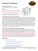
C629 Alternator Installation
CEN model C629 is a hinge mount, negative ground alternator
rated at 28V/260A. Follow these instructions to ensure proper
installation.
1. Alternators not shipped with pulley are shipped with shaft
collar, disc spring washer, and nut installed. Remove and
discard shaft collar. Make sure Woodruff key is securely
wedged in slot in shaft.
2. Install pulley with furnished at washer and locknut. Torque
pulley nut to 163 Nm/120 lb. ft. See Figure 1.
Do not hammer pulley when installing
pulley on shaft. Carefully slip-t pulley over
shaft to prevent woodruff key from moving
out of place.
Page 1 of 2
3. Install alternator on mounting bracket according to vehicle
manufacturer’s specications. Use hardened at washers
between mounting surfaces and bolt heads or lockwashers.
Mounting bolts should be Grade 5 (Metric Grade 8.8),
minimum.
4. Tension belt to vehicle manufactuer’s specications.
5. Connect vehicle B+ cable to alternator B+ terminal. Install
hardware on B+ terminal in stacking order shown in Figure 2.
Torque to 15 Nm/11 lb. ft.
6. Connect vehicle B− cable to alternator B− terminal. Install
B− hardware in stacking order shown in Figure 3. Torque to
9 Nm/7 lb. ft.
Wire gauge must be capable of handling
maximum alternator output with minimum
voltage drop. All cables must be supported
within 300 mm (12 in.) to prevent twisting,
loosening, and damage to terminals.
7. Connect alternator-to-regulator harness to regulator as
shown in Figure 1.
8. If regulator was supplied separately, install regulator
according to instructions on page 2.
NOTICE
CAUTION
C. E. Niehoff & Co. • 2021 Lee Street • Evanston, IL 60202 Tech Services Hotline 800-643-4633
Figure 2: B+ Terminal Hardware Stacking Order
Flat washer
Lock washer
Bolt, .375-16
Torque to
15 Nm/11 lb. ft.
Battery B+
wire terminal
Figure 1: C629 Alternator Connections
Slip
bushing
Mounting
bracket
Hardened
washer
CAUTION
Slip bushing in
rear mounting
foot must be tightened against
mounting bracket to prevent
damage to mounting feet and
bracket.
Figure 3: B– Terminal Hardware Stacking Order
Battery B–
wire terminal
Bolt, .3125-18
Torque to
9 Nm/7 lb. ft.
Flat washer
Lock washer
Pulley nut
Torque to
163 Nm/120 lb. ft.
Alternator-
to-regulator
harness
B +
terminal
Regulator
Flat washer
Pulley
Woodruff
key
B‒
terminal
.375-16 Threaded
insert, self-locking

Page 2 of 2 II220B
If you have questions about your alternator or any of these instructions, or if you need to locate a Factory authorized Service Distributor, please contact us at:
C. E. Niehoff & Co.• 2021 Lee Street • Evanston, IL 60202 USA
TEL: 800.643.4633 USA and Canada • TEL: 847.866.6030 outside USA and Canada • FAX: 847.492.1242
E-mail us at service@CENiehoff.com
C. E. Niehoff & Co. • 2021 Lee Street • Evanston, IL 60202 Tech Services Hotline 800-643-4633
Regulator Installation
1. Turn regulator over and make sure set point of switch at
bottom of regulator is appropriate for type of battery used in
vehicle . If necessary, change switch set point. See Figure 4
and Table 1 for voltage set point options.
2. Mount regulator on alternator with included hardware and
spacer as shown in Figure 5.
• Torque the two 10-32 hex screws with lock washer and at
washer on alternator drive-end housing to 3.4 Nm/30 lb. in.
• Place spacer between regulator housing and alternator
shell and torque .25-28 hex screw with lock washer and
at washer to 8.5 Nm/75 lb. in.
3. Securely plug alternator-to-regulator harness into receptacle
on regulator. See Figure 5 for receptacle location.
4. Connect regulator terminals as required by vehicle:
• IGN terminal (required) must receive voltage from vehicle
switched DC ignition source or multiplex in order to energize
regulator. Torque to 3.4 Nm/30 lb. in. See Figure 5.
Voltage should be present at IGN terminal
when ignition is on or engine is running. No
voltage should be present when ignition is off
or engine is not running.
• D+ terminal (if required) provides DC system battery voltage
to vehicle (5A maximum) for charge indicator lamp, relay, or
multiplex while alternator is producing output. Torque terminal
hardware to 3.4 Nm/30 lb. in. See Figure 5.
NOTICE
Figure 4: Regulator Voltage Selection Switch
Figure 5: Typical Regulator Connections
Table 1: Regulator Switch Settings
Position Remote Sensing Not Connected
1 27.5 V
2 28.0 V
3 28.5 V
4 29.0 V
Typical status
LED location
D+
terminal
IGN
terminal
Flat washer
Lock washer
Hex screw, 10-32
Torque to 3.4 Nm/30 lb. in.
(2 plcs.)
Spacer
(place between
regulator and
alternator shell)
Hex screw, .25-28
Torque to 8.5 Nm/75 lb. in.
Lock washer
Flat washer
Alternator-to-regulator
harness connector
/