Page is loading ...

1
Biddle Forceflow - LST Fan Convector
Installation, Servicing and Maintenance Instructions
(Issue 4 – 01/01/2014 onwards)
Description
The Low Surface Temperature (LST) Forceflow Fan Convector uses patented LST active control to
maintain the surface temperatures of the unit within the 43°C limit indicated by NHS Estates
document “Health Guidance Note – ‘Safe’ hot water and surface temperatures”.
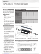
Figure 1 – Forceflow LST Fan Convector
In common with a typical fan convector the unit has a fan with motor, heating coil and air filter
housed within a painted sheet steel casing. Room air enters through the bottom return grille and
heated air is discharged out from the top grille to heat the conditioned space. The discharge grille
and surrounding metalwork on a standard fan convector can have surface temperatures higher than
43°C which would cause burns to vulnerable persons. The Biddle, Forceflow LST Fan Convector
incorporates patented LST active control technology so the casing will not go above 43°C.
Figure 1 shows the basic components of the unit. There is a Leaving Air Temperature, Thermostatic
Radiator Valve (LAT TRV) fitted in the heating coil pipework with temperature sensor located in the
air discharge of the unit. This automatically adjusts the temperature of the air that blows out of the
unit so the casing will not go above 43°C. The control head of this LAT TRV is pre-set by Biddle in
its factory and locked so it is non-adjustable by the end user or persons on site.
There is also a Room Control, Thermostatic Radiator Valve (Room Control TRV) fitted in the
heating coil pipework that controls the temperature of the room space. The Room Control TRV
automatically controls the temperature of the air in the room to achieve a satisfactory room air
temperature for comfort heating. The Room Control TRV does not compromise the action of the
LAT TRV in maintaining LST surface temperatures.
Heating Coil
Fan
Room Control
TRV Sensor
Filter
LAT TRV Sensor
flow return
Fan Control
On/Off Switch
on heating coil
Remote
Option on
capillary flow return
LAT TRV
at rear of unit
Room Control TRV
at front of unit
Room Control TRV
at front of unit
LAT TRV
at rear of unit
LH Model RH Model

2
In the standard unit the Room Control TRV has a temperature sensor located inside the bottom air
return grille of the unit, controlling the room temperature against the return air entering the unit. The
adjustable control head of the standard Room Control TRV is also fitted inside the unit casing (see
Figure 2, Page 6) and the temperature set-point is set at commissioning to, say 21°C. The access
panel of the fan convector is then closed, secured with screws and the unit left at this fixed
temperature setting.
An alternative to controlling the room temperature against a fixed return air set point is to have a
Remote Room Control which is a combined temperature sensor and set-point adjuster fitted on the
wall of the room. This has a 15m capillary which is run back to the valve body of the Room Control
TRV inside the fan convector unit and connected to the TRV valve with a threaded connector, see
Figure 5 & 6, Page 8. Whilst the capillary is only 2mm diameter the threaded connector on the end
of the capillary has a 34mm diameter knurled nut so allowance needs to be made to run this back
the unit.
The temperature of the water from the boiler heating system is used to switch the fans on and off in
the fan convector. There is an integral pipe switch fitted inside the unit which switches the fans on
when water temperature rises above 45°C and switches the fans off when water temperature cools
below 35°C. This provides “global” switching via the heating system for all the LST fan convectors
in the building. The LST Fan Convector must not be switched on and off at the electrical supply as
this will compromise the LST operation of the unit. On/Off must be done as explained above with
water temperature from the boiler heating system.
As the Room Control TRV controls the temperature of the room the fans will switch off and on when
the room temperature is close to the temperature set-point. This is quite normal and avoids fans
blowing air at an ambient temperature out of the discharge grille which could be felt as a draft to
vulnerable persons.
There is a 3-speed fan switch located inside the fan convector which can be set to High, Medium or
Low fan speed during commissioning or servicing. The access panel of the fan convector is then
closed, secured with screws and the unit left at this fixed fan speed. It is not possible to have user
remote fan speed switching as this can compromise the LST operation.
AC or EC fans can be fitted in the LST Fan Convector. With AC fans the High, Medium and Low fan
speeds can be connected to 6 available motor speed tappings at the fan motor terminal block (see
Figure 7 - Wiring Diagram, AC Fans on Page 9). With EC fans the High, Medium and Low fan
speeds can be individually adjusted to suit the site conditions via speed potentiometers on a pcb
fitted within the integral control panel (see Figure 8 - Wiring Diagram EC Fans on Page 10).

3
Design Considerations
Higher grade LPHW water flow temperatures can vary between 70°C and 90°C and the patented
Biddle LST Active Control will maintain safe casing surface temperatures and provide the maximum
heat outputs as given in Table 1 below. Water flow temperatures below 70°C will provide reduced
heat outputs to those given in Table 1.
NB. If using the LST Forceflow on compensated water circuits this should not present a problem as
lower heat output during mild weather is then desirable.
A water flow temperature of 60°C will provide c.65% of Table 1 heat output.
A water flow temperature of 50°C will provide c.45% of Table 1 heat output.
A permanent electrical supply must be made to the unit via a local isolator with 3mm contact
separation on both live and neutral poles. The unit must be earthed. The unit must not be controlled
on and off via a timed or manual switched electrical supply as this will start and stop the unit
unnecessarily and result in non-LST operation. Fan On/Off must only be via the integral fan control
switch when it detects hot water at above approximately 45°C. The electrical supply to the unit must
be left permanently energised except in the case of an emergency or when servicing the unit. To
this end, it is recommended that a notice with the wording “To be left on during normal operation”
be affixed to the local electrical isolator by the installer. It is not possible to have user remote fan
speed switching as this can compromise the LST operation.
Maximum heat outputs and corresponding water flow rates for 80°C water flow temperature are
shown in Table 1, these are for when the Room Control TRV is fully open, i.e. the design day
condition. Higher water flow rates will not produce higher heat outputs, just higher pressure drops.
This is because the leaving air temperature is fixed by the LAT TRV to achieve a safe low surface
temperature. Only an increase in fan speed and/or a decrease in return air temperature to the unit
below 20°C will produce higher heat outputs to those shown in Table 1.
Size
Fan
Speed
Air
Volume
(l/s)
Max. Heat Output
@ Flow/Return temp.
and 20°C EAT
(kW)
Water Flow
Rate @ 80°C
flow temp.
(l/s)
Hydraulic
Pressure Drop
(kPa)
915 high
medium
low
118
87
59
2.83 @ 80/63°C
2.09 @ 80/62°C
1.42 @ 80/61°C
0.041
0.028
0.018
1.6
0.8
0.3
930 high
medium
low
190
176
104
4.56 @ 80/59°C
4.22 @ 80/60°C
2.50 @ 80/60°C
0.051
0.047
0.028
2.4
2.2
0.8
935 high
medium
low
254
202
136
6.40 @ 80/57°C
5.10 @ 80/58°C
3.43 @ 80/59°C
0.068
0.057
0.040
4.5
3.2
1.6
940 high
medium
low
318
249
164
8.01 @ 80/52°C
6.28 @ 80/54°C
4.13 @ 80/56°C
0.070
0.059
0.042
5.0
3.4
1.8
975 high
medium
low
465
408
250
11.72 @ 80/55°C
10.28 @ 80/55°C
6.30 @ 80/55°C
0.114
0.100
0.062
9.8
7.7
3.0
Table 1

4
Please note that the water flow rates, water return temperatures and hydraulic pressure drops given
in Table 1 are for a water flow temperature of 80°C. This is with the unit operating at maximum
output (i.e. with the Room Control TRV fully open). Design water flow rates, water return
temperatures and hydraulic pressure drops will be different for other water flow temperatures, i.e.
70°C or 90°C. Contact the Biddle Sales office for details.
To explain this it must be understood that the maximum heat output is determined solely by the
airside heat output equation with the Room Control TRV fully open and the LAT TRV controlling the
Leaving Air Temperature (LAT) to 40°C so that maximum case temperatures are 43°C, i.e.
Air Volume x 1.2 x Increase in Air Temperature = Heat Output
For a 930 size unit at medium fan speed this would be :-
0.176 x 1.2 x (40°C LAT - 20°C EAT) = 4.22 kW
Where 40°C LAT is the mean off coil temperature to ensure that no part of the casework of
the unit is hotter than 43°C and 20°C EAT is the entering air temperature of room air back
into the unit.
The hydraulic pressure drop in column 6 of Table 1 refers to the pressure drop across all the
components within the unit, i.e. LAT TRV + Heating Coil + Room Control TRV at the water flow rate
given in column 5.
To achieve this maximum heat output with 80°C water flow temperature the flow rate of the water
has to be set as per that shown in Table 1 and this results in the water return temperatures shown
in column 4. Whilst these water temperature differentials are somewhat higher than normally seen
they should not present a problem to the designer, on the contrary it can be argued that they benefit
boiler efficiency.
Do not use a pump more powerful than is required to achieve the design water flow rates with the
hydraulic pressure drops given. The differential pressure over the thermostatic valves must not
exceed 20kPa (0.2 bar) even if the valves have shut down or the valve seat will lift compromising
the LST performance of the unit. If it is believed that high differential pressures will occur in the
partial load condition (i.e. TRV head throttling down) a suitable differential pressure regulating
device must be fitted across the flow and return pipework to each unit.
For design of the electrical installation the full load current and starting current for the unit are as
shown in Table 2.
Size Full Load Current
(Amps) Start Current
(Amps)
AC Fans EC Fans AC Fans EC Fans
915 0.2 0.1 0.3 N/A *
930 0.35 0.19 0.45 N/A *
935 0.4 0.2 0.55 N/A *
940 0.7 0.3 0.9 N/A *
975 0.9 0.65 1.2 N/A *
Table 2
* EC fans have “soft-start” so will not see a starting current higher than full load current.

5
It is important to note that the unit may not operate as a LST heat emitter until approximately 30
minutes after first turning on from cold with LPHW from the boiler operating the integral fan control
switch. An over temperature of up to 10°C could occur during this initial warm-up period, which
would usually be when the building is unoccupied. If the unit is operated continuously, such as is
typical in hospitals, retirement homes, etc. it will remain LST as demonstrated during its trials at the
BSRIA Test House.

6
Installation
Decide on the best location for the fan convector. This is often adjacent to a cold zone in the room
such as under a window or against an external wall.
Remove protective cardboard outer packaging and any polystyrene padding. You should have
received the fan convector in perfect condition. Please advise us within 5 days of receipt if it is
damaged in any way whatsoever.
Remove the front access panel (2 screws or 2 key locks) and offer the unit up to its intended
location and mark where the flow and return water pipes will enter the unit through the rectangular
entry hole in the base of the casing. Electrical connection is made to the unit at the opposite end of
the casing to the pipe connections. This can be done via the cable entry point at the bottom of the
side panel, using the cable gland supplied, or the rectangular hole in the base of the unit
NB. The unit can be manufactured with RH or LH pipe connections at the factory to suit the
installation. It is not possible to change pipework handing once the unit is on site.
Fix the unit to the wall using four suitable fixings via the keyhole slots in the rear panel and connect
water and electrical connections. The flow (inlet) and return (outlet) water connections must be
connected the right way around so the direction of water flow through the unit is correct or the unit
will be non-LST and unsafe.
For units with LH pipe connections (viewed from the front) the flow pipe is at the rear.
For units with RH pipe connections (viewed from the front) the flow pipe is at the front.
See Figure 1, Page 1 which shows the Flow and Return connections for LH and RH units and
Figure 2, below, which shows the Flow and Return connections for a LH unit.
Note also the positions of the Room Control TRV (at the front) and the LAT TRV (at the back) inside
the unit.
Figure 2
(LH pipe connections shown)
Room Control
TRV
a
t fr
o
nt
LAT TRV
at rear

7
A double check on water flow direction should be carried out using the direction of flow arrows
engraved on the TRV Valve bodies, see Figure 3 below.
Ensure the large chrome knurled fixing nut that holds the sensor capillary head to the valve body is
tight, see Figure 4 below. Using pump pliers, or equivalent, “nip up” the fixing nut just past hand
tight, no tighter.
Size 22mm compression fittings should be used to connect to the flow and return connections. Do
not use heat in this area when connecting pipework.
A permanent electrical supply must be made to the unit via a local isolator with 3mm contact
separation on both live and neutral poles. The unit must be earthed. See Wiring Diagrams – Figure
7 or 8. It is recommended that a notice with the wording “To be left on during normal operation” be
affixed to the local electrical isolator by the installer.
Figure 3
Figure 4
Chrome Knurled
Fixing Nuts

8
If a Remote Room Control TRV, Sensor Head is being used the sensor head should be positioned
on the wall in a suitable position within the room in accordance with the instructions that come with
the sensor head. The capillary from the Sensor Head should then be fed back to the fan convector
entering the unit via the square entry hole in the base of the casing (see Figure 5 below) and
connected onto the Room Control TRV (see Figure 6 below). Ensure the large chrome knurled
fixing nut that holds the sensor capillary head to the valve body is tight, see Figure 6. Using pump
pliers, or equivalent, “nip up” the fixing nut just past hand tight, no tighter.
Chrome
Knurled
Fixing Nut
Figure 5 Figure 6

9
After installation fix sticker :-
"To be left on during normal operation"
to local isolator
Permanent
Electrical Supply
230v/1ph/50Hz
NOTES
1. Dashed Line Cables - Site Wiring
2. Unit must be Earthed
Summer/Winter
(T4 Override)
Integral Pipe Switch
Thermostat T4 for
Fan On/Off
Terminal Block
2-Core Cable
Terminal
Block
5-Core Cable
Fan Motor Terminal Block
with 6 motor speed tappings
T3.15A Fuse
size 5 x 20
Fan Speed Selector
Switch - Commissioning
On/Off
Switch
E
N
L
ENL123456789
Blue
Black
Brown
Grey
Green/Yellow
Blue
Grey
Violet
Blue
Orange
Red
Brown
Black
B4
B2
A3
B6
A5
A1
12
3
Brown
Brown
Blue
Brown
White
Pink
Black
Black
1
2
12
Green/Yellow
Grey
Brown
Black
Blue
Green/Yellow
Grey
Brown
Black
Blue
Neutral High Medium Low
1234560
In-Line
Connector
21
Figure 7 – Wiring Diagram, AC Fans

10
FAN MOTOR
EC
HighMediumLow
HighMediumLow
CONGNDA/T 10V
21N3
FAN SPEED
ADJUST PCB
After installation fix sticker :-
"To be left on during normal operation"
to local isolator
Permanent
Electrical Supply
230v/1ph/50Hz
NOTES
1. Dashed Line Cables - Site Wiring
2. Unit must be Earthed
Summer/Winter
(T4 Override)
Integral Pipe Switch
Thermostat T4 for
Fan On/Off
Terminal Block
2-Core Cable
E
N
L
Blue
Brown
White
Pink
Black
Black
1
2
12
21
Terminal
Block
ENL123456789
Blue
Grey
Violet
Blue
Fan Speed Selector
Switch - Commissioning
On/Off
Switch
B4
B2
A3
B6
A5
A1
12
3
T3.15A Fuse
size 5 x 20
Orange
Red
Brown
Black
Brown
Brown
Brown
Blue
Green/Yellow
Grey
Brown
Black
Blue
A1 A2
14
12 11
A1 A2
14
12 11
A1 A2
14
12 11
Red
Yellow
Blue
White
Ferrite Clamp
Wurth 742.711.12
Figure 8 – Wiring Diagram, EC Fans

11
Commissioning
Remove front access panel (2 screws or 2 key locks). Switch on electrical power to unit.
On the integral control panel (See Figure 9) set the Summer/Winter Switch to summer and the
On/Off Switch to On and the fan should operate. Switch the fan through all three speeds with the
fan speed selector switch (High, Medium and Low) and check fan speeds correspond. Set the fan
speed to Low or Medium or High, this will be the speed the unit is then permanently set to run on.
Figure 9 – Integral Control Panel
With AC fans the High, Medium and Low fan speeds can be connected to 6 available motor speed
tappings at the fan motor terminal block (see Figure 7 - Wiring Diagram, AC Fans on Page 9).
With EC fans the High, Medium and Low fan speeds can be individually adjusted to suit the site
conditions via speed potentiometers on a pcb fitted within the integral control panel (see Figure 8 -
Wiring Diagram, EC Fans on Page 10).
Adjust the set point adjuster of the Room Control TRV to the required temperature setting, see
Table 3. The set point adjuster is fitted inside the casing on standard units or on the wall in the room
if the Room Control is remotely fitted. Check that the large chrome knurled fixing nut that holds the
sensor head to the valve body is still tight. Using pump pliers, or equivalent, check the fixing nut is
“nipped up” just past hand tight, no tighter.
Setting
Position 1 2 3 4 5
Approx.
Room
Temperature
12
14
16
18
20
22
24
28
Table 3 – Room Control TRV settings
The LAT TRV (rear TRV, see Figures 1 & 2) is factory set and locked at the correct setting. It must
not be tampered with under any circumstances. The valve head should be fixed tight onto the valve
body at the factory. Check that the large chrome knurled fixing nut that holds the valve head to the
valve body is still tight. Using pump pliers, or equivalent, check the fixing nut is “nipped up” just past
hand tight, no tighter.
Set the Summer/Winter Switch to the winter position and the fan should turn off if the heating
system is cold.
IGNORE

12
With the heating system operating ensure the flow pipe gets hot and the fan operates after a delay.
If the fan does not operate check that the integral pipe switch fitted inside the unit is correctly fitted
to the heating coil, see Figure 10 below. Replace the front access panel.
Figure 10
Integral Pipe
Switch

13
Servicing
Before carrying out any service work isolate the unit from the power supply and ensure it cannot be
accidentally restored by unauthorised personnel. Remove front access panel (2 screws or 2 key
locks).
The standard cardboard frame panel filter is not designed to be cleaned and should be replaced at
appropriate intervals, which will vary from site to site. Clean the heating coil and fans by vacuuming.
Carry out the checks as described above in “Commissioning” and replace the front access panel.
Repair and Maintenance
Short list of spare parts relevant to the Forceflow LST Fan Convector is shown in Table 4 :-
Part Name Biddle Part No.
Room Control TRV or LAT TRV – Valve Body 1 in. 0308101
Room Control TRV – Head 0308102
optional Remote Room Control TRV - Head 0308104
LAT TRV – Head 0308103
Fan On/Off Pipe Switch – T4 Thermostat 0307001
Table 4
Because of the critical nature of the unit operating within LST constraints it is very important that if
components should fail they are replaced correctly. We therefore recommend that Biddle Air
Systems carry out such work unless a fully qualified Heating Technician is available.

14
Copyright and trademarks
All the information and drawings in these instructions are the property of Biddle and may not be
used (other than for the actual operation of the device), photocopied, duplicated, translated and/or
be brought to the attention of third parties without Biddle's written permission.
The name Biddle is a registered trademark.
Guarantee
The guarantee conditions form part of the terms of delivery.
Delivery of Units
If any items of the delivery have sustained damage through transit or otherwise please contact us at
the address below within 5 days
Liability for the contents of this guide:
Care has been taken in compiling these instructions to ensure they are correct, although Biddle
disclaims all liability for damage resulting from any inaccuracies and/or deficiencies in this
documentation.
Should you find any errors or ambiguities in these instructions we would be pleased to hear from
you as it helps us to improve our documentation further.
Biddle retains the right to change the specifications stated in these instructions.
Biddle Air Systems
St. Mary's Road, Nuneaton
Warwickshire. CV11 5AU
United Kingdom
Tel: 024 7638 4233
Fax: 024 7637 3621
Email: [email protected]
Web Site: www.biddle-air.co.uk

15
Designation of Equipment : Forceflow LST Fan Convector
Series Type : Size 915, 930, 935, 940, 975
Relevant EC Council
Directives :
Applied Harmonised
Standards :
Basis of Self Attestation :
Responsible Person :
Date :
the Machinery Directive (2006/42/EC)
the Low Voltage Directive (2006/95/EC)
the Electromagnetic Compatibility Directive (2004/108/EC)
the Energy related Products Directive (2009/125/EC)
Machinery - EN ISO 14121-1:2007, EN 294:1992, EN 414:2000,
BS EN 442-2:1997
LVD - EN 60335-1:2002, +A14 incorporating A1, A2, A11,
A12 & A13, EN 60335-2-30:2009, EN 60335-2-40:2003
EMC - EN 61000-6-1:2007, EN 61000-6-3:2007 + A1:2011,
EN 61000-3-2:2006 + A2:2009, EN 61000-3-3:2008
ErP - ISO 5801:2007, ISO 12759:2010
Quality Assurance to BS EN ISO 9001 : 2008
B.S.I. Registered Firm Certificate Number FM 85224
BSRIA Test Report 19313/1
Wemtech Test Reports 6661 and 6765
ELCOLAB Test Report TR001943EMC02/01
Mr. P.Casey, Site Managing Director, Thermoscreens
1st January 2014
Signed :
Biddle Air Systems
St. Mary’s Road, Nuneaton,
Warwickshire, CV11 5AU
Telephone: +44 (0)24 7638 4233
Fax: +44 (0)24 7637 3621
EC DECLARATION OF CONFORMITY
as defined by the EC Council Directive on Machinery 2006/42/EC, the Low Voltage Directive
2006/95/EC, Electromagnetic Compatibility Directive 2004/108/EC, the Pressure Equipment
Directive 97/23/EC, the Energy related Products Directive 2009/125/EC
Herewith we declare that the air movement equipment designated below, on the basis of its design
and construction in the form brought onto the market by us in accordance with the relevant safety,
health and performance requirements of the Machinery.
If alterations are made to the machinery without prior consultations with us, this declaration
becomes invalid.
/