
Installation Instructions BGD258
Issue Date December 9, 2020
BGD258 Series BASOTROL® CE Approved Gas Valve
© 2020 BASO Gas Products 1
Part No. BASO-INS-BGD258B, Rev. D www.baso.com
BGD258 Series BASOTROL®
CE Approved Gas Valve
Installation
IMPORTANT: These instructions are intended as a
guide for qualified personnel installing or servicing
BASO Gas Products. Carefully follow all instructions
in this bulletin and all instructions on the appliance.
Limit repairs, adjustments, and servicing to the
operations listed in this bulletin or on the appliance.
!
WARNING: Fire or Explosion Hazard.
The system must meet all applicable local, national,
and regional regulations. Improper installation may
cause gas leaks, explosions, property damage, and
injuries.
!
WARNING: Fire or Explosion Hazard.
To prevent leakage of upstream gas, shut off the gas
supply at the main manual shutoff valve before
installing or servicing the BGD258 valve. Failure to
shut off the gas supply can result in the release of
gas during installation or servicing, which can lead to
an explosion or fire, and may result in severe
personal injury or death.
Mounting
!
CAUTION: Equipment Damage Hazard. To
prevent damage to the valve when mounting to
pipework, do not use a wrench on any surface other
than the casting flats provided at the inlet and outlet
ends of the valve body.
To install the BGD258 valve:
1. Shut off power to the appliance.
2. Shut off the gas at the main manual shutoff valve.
3. Label each wire with the correct terminal
designation prior to disconnection.
4. Compare the voltage on the valve with the power
source voltage to ensure the correct unit is being
installed.
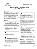
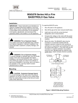
5. Mount the valve. The BGD258 valve may be
mounted on a horizontal manifold with the
magnetic operators (solenoid coils) pointed up
(vertical) or in any position not exceeding 90 from
the vertical (see Figure 1). The valve may also be
mounted on a vertical manifold in any position
around its axis. Do not install the solenoid coils
upside down. Install vertically wherever possible.
90° Maximum
from Vertical
90° Maximum
from Vertical
Limited Horizontal and Vertical
Vertical mounting may
be 360º around its axis
with the gas flow either
up or down, but always in
the direction of the arrow.
Figure 1: BGD258 Mounting Positions

BGD258 Series BASOTROL® CE Approved Gas Valve
© 2020 BASO Gas Products 2
Part No. BASO-INS-BGD258B, Rev. D www.baso.com
6. Thread pipe (the amount shown in Table 1) for
insertion into the control. Do not thread the pipe
too far. Valve distortions or malfunction may result
if the pipe is inserted too deeply.
Table 1: NPT Pipe Thread Length into Valve
Pipe Size
(NPT)
Thread Pipe
Amount (in.)
Maximum Depth
Pipe (in.)
3/8 1/2 3/8
1/2 3/4 1/2
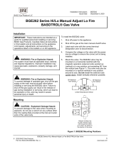
7. For any threaded connections, threads of pipe and
nipples must be smooth and free of tears and
burrs. Steam clean all piping inside diameter to
remove foreign substances such as cutting oil or
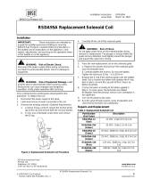
thread ships before installing into the valve. Apply
a moderate amount of goo quality pipe compound
(do not use Teflon tape) to pipe only, leaving two
end threads bare (see Figure 2). On LP
installations, use compound resistant to LP gas.
APPLY A MODERATE AMOUNT OF
PIPE COMPOUND TO PIPE ONLY
(LEAVE TWO END THREADS BARE),
CAUTION: EXCESSIVE COMPOUND
MAY BLOCK DISC OFF VALVE
SEAT CAUSING LEAKS.
CORRECT
WRONG
Figure 2: Use a Moderate Amount
of Pipe Compound
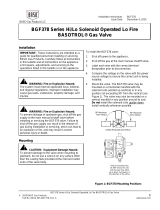
8. Ensure the gas flows through the valve body in the
direction indicated by the arrow on the body. If the
valve is installed with the gas flow in the opposite
direction of the arrow, leakage can occur. Connect
pipe to gas control inlet and outlet. Use a wrench
on the square ends of the control. If a flange is
used, place the wrench on the flange rather than
on the controls. This process should be used
for both the install and removal of the valve in
a gas system (see Figure 7). Do not use the
solenoids as leverage.
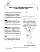
9. Connect the pilot tubing (when necessary) to the
threaded pilot connection on the underside of the
valve body (dee Figure 4) and run the tube to the
pilot burner within the appliance. Connect the pilot
tube to the valve with an optional compression
fitting.
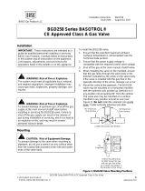
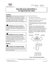
10. If you desire to measure the outlet pressure, use
the bottom cast pressure test fitting (see Figure 4)
or use the Y99AX pressure test fitting
(see Figure 3) and an approved pipe joint
compound on the male threads and replace the
marked pressure tap plug, which is optional on the
inlet or outlet of the valve body. Screw the fitting
into either side of the valve, which ever side is
convenient, replacing the pressure tap plug.
Figure 3: Y99AX-1 (1/8-27 NPT) Pressure Test Fitting
Y99AX -2 (1/8-28 BSPT) Pressure Test Fitting
11. Check for leakage before making any valve
adjustments.
a. Shut off the gas at the main manual shutoff
valve and open the pressure connection
between the manual shutoff valve and the
BGD258 valve.
b. Connect air tubing with a maximum pressure of
1-1/2 times the valve’s maximum operating
pressure (as indicated on the valve) to the
opened pressure connection.
c. Paint all valve body connections with a rich
soap and water solution.
If bubbles occur, this is an indication of a leak.
To stop a leak, tighten joints and connections.
Replace the part if the leak cannot be stopped.
If bubbles do not occur, remove the air tubing
and close the pressure connection.
12. Make wiring connections. See the Wiring section
for specific wiring instructions.
13. If installing a valve with a pressure regulator, set
the valve to the desired outlet pressure. See the
Regulator Adjustment section for specific
adjustment procedures. After setting the valve
outlet pressure, ensure that the leak-limiting seal
cap is replaced (see Figure 4).
14. Check for leakage at the pressure test nipple.
Paint the bleed hole with a rich soap and water
solution (or use acceptable gas leak detection
equipment). If bubbles occur, this is an indication
of a gas leak. To stop a leak, tighten the needle
screw. Replace the valve if the leak cannot be
stopped.

BGD258 Series BASOTROL® CE Approved Gas Valve
© 2020 BASO Gas Products 3
Part No. BASO-INS-BGD258B, Rev. D www.baso.com
15. Observe at least three complete operating cycles
to ensure that all components are functioning
correctly before leaving the installation.
Outlet Pressure
Tap Connection
Pilot Tube
Connection
Figure4: Underside of Valve with
Direct-Acting Regulator
Wiring
!
CAUTION: Risk of Electric Shock.
Disconnect power supply before making electrical
connection to avoid electric shock or equipment
damage. Ensure that the operating voltage is
identical to the information on the product
identification label.
The BGD258 valve is supplied with 2-tab or 3-tab
electrical connections. The solenoid coils are male tabs
and electrical connections should be made using
6.35 x 0.8 mm (1/4 in.) female, fully insulated push-on
terminals. The earth ground is clearly labeled.
The electrical wiring to a twin solenoid valve from an
electronic intermittent proven pilot ignition system is
comprised of two lines; a common and an independent
earth ground. Wiring can be done using a single 4-wire
cable. The wiring connections for a 4-wire cable are
shown in Figure 8.
Route the electrical cable for the valve solenoid
actuators from the burner sequence control to the valve
and make wiring connections in accordance with (see
Figure 8).
Note: Electrical connections can also be made using
pre-wired electrical plugs (DIN 43650 Form B [ISO
4400]).
Note: All wiring must be in accordance with national
and local electrical codes and regulations.
Figure 5: SVC200 Wire Connect Strain Relief
DIN Type Connector
Figure 6: SVC210 Conduit 1/2 NPT
DIN Type Connector
Setup and Adjustments
Checkout
!
WARNING: Risk of Explosion or Fire.
Follow this or an equivalent checkout procedure after
installation. Before leaving the installation, verify that
the gas valve functions properly and that the system
has no gas leaks. Gas leaks can lead to an explosion
or fire, and may result in severe personal injury or
death.
Make sure all components are functioning properly by
performing the following test:
1. Test all joints and connections for leaks with a
soap solution.
2. Close the main upstream shutoff valve and wait at
least 5 minutes for unburned gas to escape from
the appliance, and then reopen the shutoff valve.
3. Turn on the main electrical power switch and close
the thermostat contacts. The appliance should
operate in accordance with the manufacturer’s
specified sequence of operation.
4. Turn the thermostat to a low dial setting to open
the contacts. All burner flames should be
extinguished. Repeat Steps 3 and 4 at least three
times.
5. Return the thermostat to a normal setting before
leaving the installation.

BGD258 Series BASOTROL® CE Approved Gas Valve
© 2020 BASO Gas Products 4
Part No. BASO-INS-BGD258B, Rev. D www.baso.com
IMPORTANT: All adjustments must be made in
conjunction with the gas appliance and in accordance
with the appliance manufacturer’s instructions. Only
authorized personnel should make adjustments.
!
WARNING: Risk of Explosion or Fire. The
minimum flow rate of the valve must not be adjusted
below the minimum safe working rate of the
appliance. This may cause gas leaks, which can lead
to an explosion or fire and may result in severe
personal injury or death.
The BGD258 can have a bottom adjust, right or
left-handed top adjust spring pressure regulator. Right
of left-hand orientation is determined by the position of
the adjustment when looking into the inlet connection of
the valve.
The regulator controls the gas pressure at the valve
outlet by positioning the regulator poppet for selected
throughput flow and pressure. This is achieved by the
valve outlet pressure acting on the regulator diaphragm,
which balances against the preset regulator spring.
Adjustment of the spring compression determines the
valve outlet pressure and the throughput flow rate.
Regulator Adjustment
To adjust the outlet pressure, remove the leak-limiting
seal cap to expose the adjusting screw (see Figure ).
Turn the screw (using a suitable screwdriver) in a
clockwise direction to increase or in a counterclockwise
direction to decrease the outlet pressure of the valve.
Table 1: Replacement Solenoid Coil
Part Number Description
RSDA95A-12 12 VDC; 2-tab 10.5 VA Coil
RSDA95A-25V 25 VDC; 3-tab 11.5 VA Coil
RSDA95A-25 25 VAC; 50/60 Hz; 3-tab 10.5 VA Coil
RSDA95A-25A 25 VAC; 50/60 Hz; 2-tab 10.5 VA Coil
RSDA95A-120 120 VAC; 60/60 Hz; 3-tab 10.5 VA Coil
RSDA95A-240 240VAC; 50/60 Hz; 3-tab 10.5 VA Coil
Do not make field repairs except for the replacement of
the solenoid coil.
Any attempt to repair this assembly voids the
manufacturer’s warranty. For a replacement coil or gas
valve, contact the original equipment manufacturer or
the nearest BASO Gas Products distributor.
Maintenance Schedule
Preventive maintenance programs are an important
part of maintaining optimum and safe function of your
BASO products. Commercial cooking and other heating
equipment can be a heavy cycling demand on gas
safety controls.
The maintenance programs should include frequent
checkout of the gas controls. Review the procedure as
described in the setup and adjustments and check for
leakage section of the instructions.
Exposure to water, chemicals, dirt, heat and grease can
all contribute to premature shut down of the gas
controls.
The frequency of the maintenance must be determined
by the appliance manufacturer where the controls are
installed and the end user for each individual
application.
Things to consider when determining a preventive
maintenance program:
Number of cycles a gas control will see
annually (more than 20,000 cycles). The gas
control should be checked monthly.
Gas controls used less than 20,000 cycles
should be checked before every shutdown and
restart process.
Heavy grease, high heat, wash down exposure,
corrosive environment areas should be
checked with a higher frequency to prevent
premature shutdown from rapid deterioration.
Simply doing a scheduled maintenance program will
help remove the chances of a costly unexpected
shutdown.
Never try to repair or replace a gas control unless you
are an authorized licensed gas contractor as this will
void the manufactures warranty. In all cases, use an
authorized licensed gas contractor for any gas control
replacement.

BGD258 Series BASOTROL® CE Approved Gas Valve
© 2020 BASO Gas Products 5
Part No. BASO-INS-BGD258B, Rev. D www.baso.com
APPLY WRENCH TO THE FLATS
FROM THE TOP OR BOTTOM
OF THE GAS CONTROL VALVE
Figure 7: Proper Use of Wrench on Gas Control

BGD258 Series BASOTROL® CE Approved Gas Valve
© 2020 BASO Gas Products 6
Part No. BASO-INS-BGD258B, Rev. D www.baso.com
L
N
L
N
Non-Polarity Sensitive
Line and Neutral
Connections
Non-Polarity Sensitive
Line and Neutral
Connections
To Main SolenoidTo Pilot Solenoid
L2
N2
N1
L1
Coil 2
Main
Valve
Coil 1
Pilot
Valve
Earth Ground
Line 2
Neutral
Line 1
Twin Solenoid Wiring Using 4-Wire Cable
Ground Tab
25V, 120V and 240V Only
Ground Tab
25V, 120V and 240V Only
Figure 8: 3-Tab Electrical Connections

BGD258 Series BASOTROL® CE Approved Gas Valve
© 2020 BASO Gas Products 7
Part No. BASO-INS-BGD258B, Rev. D www.baso.com
Technical Specifications
Product
BGD258 Series CE Approved Gas Valve
Types of Gas
2nd (Natural Gas), and 3rd (LP Gas) Family Gases
Permissible Ambient
Temperature
(Min./Max.)
-29 to 79C (-20 to 175F)
Electrical Ratings 12 VDC, 0.875A
25 VDC, 0.46A
25 VAC, 50/60 Hz, 0.42A
120 VAC, 50/60 Hz, 0.088A
240 VAC, 50/60 Hz, 0.044A
Rated Inlet Pressure North America:
Europe:
Australia:
1/2 psi
35 mbar
3.5 kPa
Maximum Working
Pressure (CE)
50 mbar
Maximum Differential
Pressure
20 mbar (2 kPa [8 in. W.C.])
Reverse Pressure Rating 50 mbar (5 kPa [20 in. W.C.]) Class B (EN 126 and 161);
Class 2 (AS 4624 and AS 4629)
Regulator Clas
sification
Class C (EN 126); Adjustable, Class 2, Grade 20 (AS 4624)
Regulator Adjustment
Range
Bottom Adjust Regulators:
Top Adjust Regulators
7.5 to 12.5 mbar (0.75 to 1.25 kPa [3 to 5 in. W.C.])
22.5 to 30 mbar (2.25 to 3.0 kPa [9 to 12 in. W.C.])
7.5 to 12.5 mbar (0.75 to 1.25 kPa [3 to 5 in. W.C.])
22.5 to 30 mbar (2.25 to 3.0 kPa [9 to 12 in. W.C.])
Body Connections 3/8 or 1/2 NPT, 3/8 or 1/2 BSPP (Thread ISO 7-Rp) or 3/8, 1/2 BSPT (Thread ISO 7-Rc) with
Flange Connection Holes (M4 x 0.7 mm pitch x 6 mm deep)
Valve Torsi
on
Group
Group 2 (EN 126 and 161)
Pressure Connection 1/8 BSPP (Thread ISO 7-Rp), 1/8 BSPT (Thread ISO 7-Rc),
1/8 NPT Left-hand and/or Right-hand, or M5 x 0.8 Thread Bottom
Pilot Connection 1/8 BSPP (Thread ISO 7-Rp), 1/8 BSPT (Thread ISO 7-Rc),
1/8 NPT Left-hand and/or Right-hand, or 1/4 in. cc Fitting Bottom
Dirt Strainer
0.9 mm (0.036 in.) mesh (CE only or upon request)
Operating Time Rating
100% Continuous
Valve Timings Closing Time:
Opening Time:
Dead Time:
< 1 Second
< 1 Second
< 1 Second
Power
Ra
ting
10.5 VA per Coil (except 25 VDC, 11.5 VA)
Electrical Connection 2-Tab Solenoid Coil: 2 x 6.35 mm (1/4 in.)
3-Tab Solenoid Coil: 2 x 6.35 mm (1/4 in.) + 6.35 mm (1/4 in.) Earth Ground
Coil
Insulation Class
Class F
Packaging
Bulk pack supplied to original equipment manufacturer (individual pack optional).
Bulk Pack Quantity
30 per carton
Bulk Pack Weight
35 kg (77 lb) per carton
Accessories Conversion Kits Natural gas to LP gas:
LP gas to Natural gas:
Regulated to non-regulated:
GM-70-CLP
GM-70-CNG
BG-70-CBP

BGD258 Series BASOTROL® CE Approved Gas Valve
© 2020 BASO Gas Products 8
Part No. BASO-INS-BGD258B, Rev. D www.baso.com
Technical Specifications (continued)
Agency Listings CSA (AGA/CGA) Certificate Number 229521-1656041
EC Certificate Number EC-86/11/041
UL File Number MH5939
Australian Gas Certificate Number 7934
Specification Standards EN 126 and 161
Standards Complying with the Directive
Standards Complying with the Low Voltage Directive
Australian Standards AS 4624 and AS 4629
Canadian Standards CSA 6.5 and 6.20
ANSI Standards Z21.21 and Z21.78
Performance specifications are nominal and conform to acceptable industry standards. All agency certification of BASO products is performed
under dry and controlled indoor environmental conditions. Use of BASO products beyond these conditions is not recommended and may void
the warranty. Product must be protected if exposed to water (dripping, spraying, rain, etc.) or other harsh environments. The original
equipment manufacturer or end user is responsible for the correct application of BASO products. Consult BASO Gas Products LLC for
questionable applications. BASO Gas Products LLC shall not be liable for damages or product malfunctions resulting from misapplication or
misuse of its products.
Refer to the BGD258 Series BASOTROL CE Approved Product Bulletin (BASO-PB-BGD258) for necessary information on operating and
performance specifications for this product.
450 East Horseshoe Road
PO Box 170
Watertown, WI 53094 www.baso.com
1
-
877
-
227
-
6
4
27 (1
-
877
-
BASOGAS
)
Published in U.S.A.
-
 1
1
-
 2
2
-
 3
3
-
 4
4
-
 5
5
-
 6
6
-
 7
7
-
 8
8


Ask a question and I''ll find the answer in the document
Finding information in a document is now easier with AI
Related papers
-
 Baso BGG258 Series Installation guide
-
 Baso BGA158 Series Installation guide
-
 Baso RSDA Series Installation guide
-
 Baso BGE258 Series Installation guide
-
 Baso BGD258 Series Installation guide
-
 Baso BGE278 Series Installation guide
-
 Baso BGG278 Series Installation guide
-
 Baso BGE262 Series Installation guide
-
 Baso BGC258 Series Installation guide
-
 Baso BGF378 Series Installation guide


Other documents
-
Wolf AIR Owner's manual
-
Star Manufacturing 401-A Installation guide
-
Honeywell VR400/VR800 Series Operating instructions
-
Vulcan-Hart 924RX User manual
-
Vulcan Materials 924RX User manual
-
solus Fire Pit User manual
-
Johnson Controls Y99AB-4 Application Note
-
Garland H280 User manual
-
Reznor RX Operating instructions
-