PRECISION
5500
VEHICLE SECURITY SYSTEM
WITH REMOTE START
PRECISION
2200
REMOTE START ONLY
PRODUCT MANUAL

Limited
Lifetime
Warranty
This system is warranted to the original purchaser, to be free from defects in material and
workmanship. The manufacturer will repair or replace at its option, and free of charge for the first
twelve (12) months, any part that proves defective in material or workmanship under normal
installation, use, and service, provided the product is returned to the manufacturer freight
prepaid. After the first 12 month warranty period there will be a maximum service charge of
$25.00 per calendar year (if required) for repair and/or replacement of any defective parts.
A copy of the original purchase and installation receipt must accompany any products
returned for warranty service. Warranty is limited to defective parts and/or replacement parts
only and excludes any incidental, and consequential damages connected therewith.
The manufacturer of this theft deterrent system makes no warranty against the theft of the vehicle
or its contents. This warranty is not to be construed as an insurance policy against loss.
WARRANTY OF INSTALLATION LABOR, REMOVAL AND RE-INSTALLATION CHARGES ARE
NOT THE RESPONSIBILITY OF THE MANUFACTURER.
Note: This Warranty is voided if the product was not installed by an
Authorized ScyTek Dealer.

1. About Your System . . . . . . . . . . . . . . . . . . . . . . . . . . . . . . . . . . . . . . . . . . . . . . . . . . . . . . .Page 1
2. Remote Transmitters . . . . . . . . . . . . . . . . . . . . . . . . . . . . . . . . . . . . . . . . . . . . . . . . . . . . . .Page 2
Remote Transmitter Description . . . . . . . . . . . . . . . . . . . . . . . . . . . . . . . . . . . . . . . . . .Page 3
Adding/Replacing Transmitters . . . . . . . . . . . . . . . . . . . . . . . . . . . . . . . . . . . . . . . . . .Page 3
Two Car Operation . . . . . . . . . . . . . . . . . . . . . . . . . . . . . . . . . . . . . . . . . . . . . . . . . . .Page 3
Battery Replacement . . . . . . . . . . . . . . . . . . . . . . . . . . . . . . . . . . . . . . . . . . . . . . . . .Page 3
2-way LCD Remote Transmitter Description . . . . . . . . . . . . . . . . . . . . . . . . . . . . . . . . .Page 4
Adding/Replacing 2-way Transmitters, Programable features and descriptions. . . . . . Page 4-8
LCD Transmitter Battery Replacement . . . . . . . . . . . . . . . . . . . . . . . . . . . . . . . . . . . . .Page 5
3. System Operation . . . . . . . . . . . . . . . . . . . . . . . . . . . . . . . . . . . . . . . . . . . . . . . . . . . . . . . .Page 9
Remote Arming*/Locking . . . . . . . . . . . . . . . . . . . . . . . . . . . . . . . . . . . . . . . . . . . . . .Page 9
Remote Disarming*/Unlocking . . . . . . . . . . . . . . . . . . . . . . . . . . . . . . . . . . . . . . . . . . .Page 9
Tamper Alert* . . . . . . . . . . . . . . . . . . . . . . . . . . . . . . . . . . . . . . . . . . . . . . . . . . . . .Page 10
Silent Arming*/Locking -Disarming*/Unlocking . . . . . . . . . . . . . . . . . . . . . . . . . . . . . .Page 10
Passive Arming* . . . . . . . . . . . . . . . . . . . . . . . . . . . . . . . . . . . . . . . . . . . . . . . . . . . .Page 10
Panic Mode . . . . . . . . . . . . . . . . . . . . . . . . . . . . . . . . . . . . . . . . . . . . . . . . . . . . . . .Page 11
Emergency Override* . . . . . . . . . . . . . . . . . . . . . . . . . . . . . . . . . . . . . . . . . . . . . . . .Page 11
Optional Coded Emergency Override* . . . . . . . . . . . . . . . . . . . . . . . . . . . . . . . . . . . .Page 11
Automatic Rearming* . . . . . . . . . . . . . . . . . . . . . . . . . . . . . . . . . . . . . . . . . . . . . . . .Page 12
Valet Mode/ Driver Calling Feature . . . . . . . . . . . . . . . . . . . . . . . . . . . . . . . . . . . . . . .Page 12
4. Remote Start Features . . . . . . . . . . . . . . . . . . . . . . . . . . . . . . . . . . . . . . . . . . . . . . . . . . . .Page 13
Remote Starting . . . . . . . . . . . . . . . . . . . . . . . . . . . . . . . . . . . . . . . . . . . . . . . . . . . .Page 13
Shut Down . . . . . . . . . . . . . . . . . . . . . . . . . . . . . . . . . . . . . . . . . . . . . . . . . . . . . . .Page 13
Quick Stop . . . . . . . . . . . . . . . . . . . . . . . . . . . . . . . . . . . . . . . . . . . . . . . . . . . . . . . .Page 13
Automatic Start Mode . . . . . . . . . . . . . . . . . . . . . . . . . . . . . . . . . . . . . . . . . . . . . . . .Page 14
Turbo Timer Feature . . . . . . . . . . . . . . . . . . . . . . . . . . . . . . . . . . . . . . . . . . . . . . . . .Page 14
Manual Transmission Remote Starting . . . . . . . . . . . . . . . . . . . . . . . . . . . . . . . . . . .Page 15
5. Extended Features . . . . . . . . . . . . . . . . . . . . . . . . . . . . . . . . . . . . . . . . . . . . . . . . . . . . . . .Page 16
Ignition Door Locking . . . . . . . . . . . . . . . . . . . . . . . . . . . . . . . . . . . . . . . . . . . . . . . .Page 16
Ignition Door Unlocking . . . . . . . . . . . . . . . . . . . . . . . . . . . . . . . . . . . . . . . . . . . . . .Page 16
Dome Light Activation . . . . . . . . . . . . . . . . . . . . . . . . . . . . . . . . . . . . . . . . . . . . . . . .Page 16
Auxiliary Function Outputs . . . . . . . . . . . . . . . . . . . . . . . . . . . . . . . . . . . . . . . . . . . .Page 16
Disarm with Auxiliary Function* . . . . . . . . . . . . . . . . . . . . . . . . . . . . . . . . . . . . . . . . .Page 16
Remote Sensor Disable* . . . . . . . . . . . . . . . . . . . . . . . . . . . . . . . . . . . . . . . . . . . . . .Page 16
6. System Installation . . . . . . . . . . . . . . . . . . . . . . . . . . . . . . . . . . . . . . . . . . . . . . . . . . . . . .Page 17
Mounting the Control unit . . . . . . . . . . . . . . . . . . . . . . . . . . . . . . . . . . . . . . . . . . . . .Page 18
Mounting the Siren* . . . . . . . . . . . . . . . . . . . . . . . . . . . . . . . . . . . . . . . . . . . . . . . . .Page 18
Mounting the Shock Sensor* . . . . . . . . . . . . . . . . . . . . . . . . . . . . . . . . . . . . . . . . . . .Page 18
7. System Wiring . . . . . . . . . . . . . . . . . . . . . . . . . . . . . . . . . . . . . . . . . . . . . . . . . . . . . . . . .Page 19
6-Pin Starter Harness . . . . . . . . . . . . . . . . . . . . . . . . . . . . . . . . . . . . . . . . . . . . . . . .Page 19
20-Pin Main Harness . . . . . . . . . . . . . . . . . . . . . . . . . . . . . . . . . . . . . . . . . . . . . . . . .Page 19
Plug-in Connectors . . . . . . . . . . . . . . . . . . . . . . . . . . . . . . . . . . . . . . . . . . . . . . . . . .Page 20
8. Jumper Settings . . . . . . . . . . . . . . . . . . . . . . . . . . . . . . . . . . . . . . . . . . . . . . . . . . . . . . . .Page 21
Jumper Selection . . . . . . . . . . . . . . . . . . . . . . . . . . . . . . . . . . . . . . . . . . . . . . . . . . .Page 21
9. System Programming . . . . . . . . . . . . . . . . . . . . . . . . . . . . . . . . . . . . . . . . . . . . . . . . . . . . .Page 22
Entering System Programming . . . . . . . . . . . . . . . . . . . . . . . . . . . . . . . . . . . . . . . . . .Page 22
Default Reset . . . . . . . . . . . . . . . . . . . . . . . . . . . . . . . . . . . . . . . . . . . . . . . . . . . . . .Page 22
Programmable System Options for
5500 Series
. . . . . . . . . . . . . . . . . . . . . . . . . . . .Page 22
Programmanble System Options for
2200 Series
. . . . . . . . . . . . . . . . . . . . . . . . . . . .Page 25
10. Relay Diagrams . . . . . . . . . . . . . . . . . . . . . . . . . . . . . . . . . . . . . . . . . . . . . . . . . . . . . . . . .Page 28
11. Door Lock Diagrams . . . . . . . . . . . . . . . . . . . . . . . . . . . . . . . . . . . . . . . . . . . . . . . . . . . . .Page 29
12. Two Stage Door Lock Diagrams . . . . . . . . . . . . . . . . . . . . . . . . . . . . . . . . . . . . . . . . . . . Page 30
13. Technical Information . . . . . . . . . . . . . . . . . . . . . . . . . . . . . . . . . . . . . . . . . . . . . . . . . . . .Page 32
14. System Diagnostics . . . . . . . . . . . . . . . . . . . . . . . . . . . . . . . . . . . . . . . . . . . . . . . . . . . . . .Page 33
15. Wiring Diagram . . . . . . . . . . . . . . . . . . . . . . . . . . . . . . . . . . . . . . . . . . . . . . . . . . . . . . .Back Page
Table
of
Contents


The ScyTek Precision 5500 Series is a
Combination Vehicle Security and Remote Starting System
that will have features and functions that will be described in the following sections with an
ASTERICK
*
The Precision 2200 Series is a
Remote Start System only
. Both series feature a built-in "ScyNet
Network Port" that allows direct connection of optional accessory modules and a PC interface offering
expanded system operation. With proper installation this system will provide superior protection and/ or
performance for many years to come.
The Precision’s 5500 and 2200 Series built-in remote starter is designed to offer maximum convenience by
remote starting your vehicle’s engine, turning on the heater/air conditioner, and then running for a pre-
determined time to provide a comfortable environment once you enter your vehicle.
To ensure the safety and security of the system while it is remote started, the Precision 5500 and 2200
Series employs several safeguards. In the event the alarm is triggered while the engine is remotely running,
the remote start will immediately shutdown to prevent unauthorized users from attempting to drive the
vehicle. The system is equipped with a hood pin input to prevent access to the engine compartment while
the vehicle is remotely running. The Valet Mode prevents the remote start feature from operating in the
event the vehicle is to be serviced. Finally, the brake pedal also acts as a safety by shutting down the
remote start when pressed.
System Contents:
• Main Unit with built-in ScyNet Network Interface Port
• One 5-Button 2-Way LCD Remote & One 1-Way 5-Button Sleek Carbon Fiber Transmitter
• * High Output 6-tone Siren
• * Dual Stage Shock Sensor
• LED/Coded Emergency Override / Valet Switch/ Call button - built into the antenna (see page 32)
Optional ScyNet Network Interface Accessories:
• ScyNet Network Interface Software
Options and Convenience Features
**
This ScyTek system includes several optional inputs and outputs allowing the creation of a completely
personalized security and convenience system by offering many optional features such as:
**May require additional parts and/or labor, see store for details.
· Second Car Operation
· Keyless Entry
· Two Stage Door Unlocking
· * Starter Defeat
· Horn Honk
· Illuminated Entry
· Turbo Timer
· Remote Window Control
· Power Trunk / Hatch Release
· * Glass Breakage Sensor
· * Radar Sensor
· Remote Head Lamp Control
· * Back-up Battery Siren
About
Your
System
Some of the features described in this manual may require additional parts and/or labor, and may not be
included as part of the standard installation of this unit. Additionally, many features of these systems
have selectable options that must be activated or programmed during the system’s installation. These
items will be identified in the following sections. Please discuss these features and any questions you
may have regarding the installation of this product with Your Authorized Dealer.
Precision - Page 1

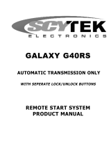
Standard Remote Transmitter Description
The Precision 5500, 2200 Series is supplied with one 5-button Remote Transmitter that is used to control
the system’s operations.
Note: Using the optional PC or Pocket PC interface with the network software, it is possible to reconfigure
the functionality of the transmitter buttons. The standard (default) setting for operation of the transmitters
is described below.
Button 1
Arms* and Locks the system and when held for 5 seconds, activates the system’s Panic feature.
Button 1 also locks the doors when the system is in Valet Mode.
Button 2
Disarms* and Unlocks the system. Pressing Button 2 again operates the Passenger Unlock feature
(if installed).
Button
2 also unlocks the doors when the system is in Valet Mode.
Button 3
Activates the Auxiliary 1 output. This output will remain on for as long as the button is pressed.
Button 4
Activates the Remote Start feature.
Button 5
is the Page Shift button. Each time the Shift Button is pressed, the LED on the transmitter will
illuminate and the transmitter functions will shift to the next page, allowing access to another set of
features. Once shifted to another page (there are 4 pages total), the transmitter will remain on that page
for 10 seconds or until a button is pressed, then it will return to page 1. Under normal operation, only
pages 1 and 2 are used. Pages 3 and 4 are usually used for Two Car Operation (see page 3) or optional
expansion modules.
Shift then Button 1
Arms*/Locks the system silently.
Shift then Button 2
Disarms*/Unlocks the system silently.
Shift then Button 3
Activates the Auxiliary 2 output. This output will remain on for as long as the button
is pressed.
Shift then Button 4
Activates the Auxiliary 3/Factory rearm output.
Remote
Transmitters
Button 1
Button 2
Button 5
LED
Button 3 Button 4
Page 2 Precision

Adding/Replacing Standard Remote Transmitters
To replace lost or stolen transmitters or to add additional transmitters into the system, have all desired
transmitters ready and follow the steps below.
Note: Up to 4 one-way transmitters can be programmed to operate the system. Any previously stored
transmitter will be erased if it is not programed within the following sequence
To program the transmitter(s):
1. Turn the ignition key On, Off, On, Off, and back On. (Key On 3 times)
· 3 seconds later The siren*/horn will chirp/honk 3 times.
2. Press and hold the Override switch for 5 seconds.
· The siren*/horn will chirp/honk 5 times.
· The LED will illuminate.
3. Press Button 1 on the first transmitter.
· The siren*/horn will chirp/honk once.
4. Press Button 1 on the first transmitter again.
· The siren*/horn will chirp/honk twice to indicate it has learned the code.
5. Repeat steps 3 and 4 for each transmitter (up to 4).
6. Turn off the ignition key.
Two Car Operation
If two vehicles are equipped with the Precision 5500 and/or 2200 Series systems, for convenience both can
be operated using the same remote transmitter. If all four transmitters are to be used with both cars,
program transmitters A and B into the first vehicle in the manner described above. Program transmitters
C and D by pressing the Shift button twice before performing steps 3 and 4 above.
When finished programming the first vehicle, program transmitters C and D into the second vehicle as
normal, then program transmitters A and B by pressing the Shift button twice before performing steps 3
and 4 above.
When programmed in this manner, the driver of the first car can also operate the second vehicle by pressing
the Shift button twice and the desired function button.
Battery Replacement
Your Remote Transmitter uses two 3 volt lithium batteries (type CR2016), which will require
replacement in time. Depending on the amount of use, the batteries may last up to six months
or more before they need replacement.
In order to change the battery, first remove the screw from the back of the transmitter and separate the
top and bottom halves of the case. While replacing the battery make sure that the positive and negative
terminals are positioned correctly, then carefully reassemble the transmitter case.
Precision - Page 3

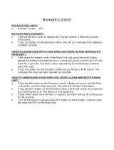
2-way LCD Remote Transmitter Description
The Precision 5500 and 2200 are supplied with a 2-way LCD remote transmitter, offering increased range
and confirmation of any activated features.
Page 1
Button 1
Arms* and Locks the system and when held for 5 seconds, activates the system’s Panic feature.
Button 1 also locks the doors when the system is in Valet Mode.
Button 2
Disarms* and Unlocks the system. Pressing Button 2 again operates the Passenger Unlock feature
(if installed).
Button
2 also unlocks the doors when the system is in Valet Mode.
Button 3
Activates the Auxiliary 1 output normally used for trunk release (note trunk icon on button).
Button 4
Activates the Remote Start feature.
Button 5
is the Confirmation, Programming and the Page Shift button. Quickly pressing button 5 will activate
the Page 2 function. Pressing button 5 for 2 seconds activates the system’s confirmation feature which will
then display the current status of the system (armed, disarmed, engine running, etc.).
Page 2
Button 1
Silently Arms*/Locks the system.
Button 2
Silently Disarms*/Unlocks the system.
Button 3
Activates the Auxiliary 2 output.
Button 4
Aux 3 or Factory Rearm output.
Button 5
Not Implemented.
Page 3 & 4 are used as Page 1 & 2 for second car operation
Adding/Replacing 2-way LCD Transmitters
When adding a 2-way LCD transmitter to the system ( maximun of two LCD Transmitters total) Any
previously stored transmitter will be erased if it is not programed within the following sequence.
follow these steps:
1. Turn the ignition key On, Off, On, Off, On, Off, and back On. (Key On 4 times)
· 3 seconds Later the siren*/horn will chirp/honk 4 times.
2. Press and hold the Override switch for 5 seconds .
· The siren*/horn will chirp/honk 4 times.
· The LED will illuminate.
Button 1 Button 2
Button 3
Button 4
Button 5
Page 4 - Precision

3. Press and release Button 1 on the first transmitter, then on the second transmitter.
· The siren*/horn will chirp/honk once for every transmitter learned.
4. Turn off the ignition key.
5. The siren*/horn will chirp/honk 3 times to indicate the system has exited programming mode.
LCD Transmitter Battery Replacement
Your Precision Remote Transmitter uses a 1.5 volt AAA alkaline battery, which will require replacement in
time. Depending on the amount of use, the battery may last up to 3 months before it needs replacement.
When the battery needs replacing, the system’s operating range will decrease, the LCD display will show
only one of three bars in the battery icon, or the display and sounds may suddenly stop and start as the
battery voltage drops below minimum.
In order to change the battery, first slide the battery door locking pin to the side. Carefully slide the battery
cover downward until it is free. While replacing the battery make sure that the positive and negative
terminals are positioned correctly, then carefully reassemble the transmitter case.
Setting The Time
The LCD display is equipped with a 12-hour clock that in addition to displaying the time, offers an alarm
clock function as well as a remote activation timer.
To set the time:
1. Press and hold Buttons 2 and 3 for three seconds.
· The remote will beep two times and three bars will be shown indicating time set mode is entered.
2. Press and release Button 2 until the correct hour is displayed. (hold button to scroll).
3. Press and release Button 3 until the desired minute is displayed. (hold button to scroll).
4. When the desired time is displayed, press Button 5 to store.
· The remote will beep 3 times to indicate the time has been set.
Setting The Alarm Clock
The alarm clock function can be set to play an alert melody at a specific time of day.
To set the alarm clock function:
1. Press and hold Buttons 2 and 3 until the remote beeps three times.
· The alarm clock bell and three bars will be shown indicating alarm clock set mode is entered.
2. Press Button 2 until the desired hour is displayed.
3. Press Button 3 until the desired minute is displayed. The button may be held down to scroll faster.
4. When the desired time is displayed, press Button 5 to store.
· The remote will beep 3 times to indicate the alarm clock has been set.
To disable the alarm clock function:
1. Press and hold Buttons 2 and 3 until the remote beeps three times.
· The alarm clock bell and three bars will be shown indicating alarm clock set mode is entered.
2. Press Button 1 to disable the alarm clock.
· The remote will beep 3 times and show OFF to indicate the alarm clock has been disabled.
Setting The Daily Start Function
( transmitter must be within 1500ft to reliably start)
The Daily Start Function provides a timer that allows the vehicle to automatically remote start at a preset
time of day.
Precision - Page 5

To set the daily start feature:
1. Press and hold Buttons 2 and 3 until the remote beeps four times.
· The fan and clock will be shown indicating daily start mode is entered.
2. Press Button 2 until the desired hour is displayed.
3. Press Button 3 until the desired minute is displayed. The button may be held down to scroll faster.
4. When the desired time is displayed, press Button 5 to store.
· The remote will beep 3 times to indicate the daily start function has been set.
To disable the daily start feature:
1. Press and hold Buttons 2 and 3 until the remote beeps four times.
· The fan and clock will be shown indicating daily start mode is entered.
2. Press Button 1 to disable the daily start function.
· The remote will beep 3 times to indicate the daily start function has been disabled.
Setting The Automatic Cold Start Temperature
(
2 step procedure, for second step see page 7 under
c
o
)
The Automatic Cold Start setting sets the temperature threshold. If automatic start is set to cold temperature setting,the
starter will activate every 2 or 4 hours if the temperature drops bellow the set value.
1. Press and hold Buttons 2 and 3 until the remote beeps five times.
·
c
o
will be shown indicating automatic cold start temperature set mode is entered.
2. Press Button 2 to increase the temerature.
3. Press Button 3 to decrease the temperature.
4. When the desired temperature is displayed, press Button 1 to store the value.
· The remote will display the temperature and beep 3 times then 4 times to indicate the set temperature.
Setting The Automatic Hot Start Temperature
(
2 step procedure, for second step see page 7 under
h
o
)
The Automatic Hot Start setting sets the temperature threshold. If automatic start is set to hot temperature setting, the
starter will activate every 2 or 4 hours if the temperature rises above the set value.
1. Press and hold Buttons 2 and 3 until the remote beeps six times.
·
h
o
will be shown indicating automatic hot start temperature set mode is entered.
2. Press Button 2 to increase the temerature.
3. Press Button 3 to decrease the temperature.
4. When the desired temperature is displayed, press Button 1 to store the value.
· The remote will display the set temperature and beep 3 times then 4 times to indicate the set temperature.
LCD Backlight
Transmitter Button 5 is used for confirmation, transmitter programming, as well as activation of the LCD
backlighting for use in the dark. Press and release button 5 momentarily to activate the LCD backlight.
System Confirmation
The 2-way transmitter's confirmation feature allows the current vehicle status to be displayed at any time.
To display system status:
1. Press and hold Button 5 until the display shows CON.
· The transmitter will beep once.
2. Release Button 5.
· The transmitter will beep once.
· The LCD panel will display the current system status.
Programmable Functions using the LCD Transmitter
Pressing and holding transmitter button 5 will scroll through several transmitter programmable options -
dEG, CHP, snd, PSV, VAL,
C
O
and
h
O
.
dEG Check the temperature inside the vehicle
1. Press and hold Button 5 until the display shows DEG
·The transmitter will beep twice.
2. Release Button 5.
· The transmitter will beep four times.
· The LCD panel will display the temperature inside the vehicle
Page 6 - Precision

Precision - Page 7
CHP Set the siren*/horn confirmation chirps*/honks ON or OFF:
1. Press and hold Button 5 until the display shows CHP.
·The transmitter will beep three times.
2. Release Button 5.
· The transmitter will beep once.
· The LCD panel will show a siren if the chirps*/honks are enabled or "off" if the chirps*/honks are
disabled.
snd sound function selects the transmitter's confirmation mode - Tone or Vibration mode.
Set the transmitter confirmation tones ON or OFF:
1. Press and hold Button 5 until the display shows SND.
· The transmitter will beep four times.
2. Release Button 5.
· The transmitter will beep once.
· The LCD transmitter will beep 5 times and display “on” if the sounds are enabled or vibrate and
display "off" for the Remote to vibrate.
PSV* passive mode function enables or disables the security systems passive arming mode.
Enable or disable the passive arming mode:
1. Press and hold Button 5 until the display shows PSV.
· The transmitter will beep five times.
2. Release Button 5.
· The transmitter will beep once.
· The LCD panel will play a tone and display “on” if enabled or "off" if disabled.
VLT Valet mode function sets and resets the security system valet mode.
** this function is enabled only when the system is disarmed/ unlocked.
Set or reset the Valet mode:
1. Press and hold Button 5 until the display shows VLT.
· The transmitter will beep six times.
2. Release Button 5.
· The LCD panel will play a tone and the siren*/horn will chirp/honk once if the Valet mode was set
and the symbol “V" will be displayed indicating that the system is in Valet mode.
· The transmitter will beep twice and the siren will chirp twice if the Valet mode was reset. The symbol
“V" will turn off indicating that the security system is out of Valet mode.
C
O
Auto Start Cold Temperature Activation Mode.
1. Press and hold Button 5 until the display shows
C
O
.
· The transmitter will beep 7 times.
2. Release Button 5.
· The transmitter will beep once.
· The LCD panel will show Auto Start Cold Temperature setting.
3. Press and hold Button 5 until the display shows CON.
4. Release Button 5.
· The transmitter will beep once.
· The LCD panel will show "ON" indicating that Auto Start Cold Temperature Activation
Mode is enabled.
h
O
Auto Start Hot Temperature Activation Mode.
1. Press and hold Button 5 until the display shows
h
O
.
· The transmitter will beep 8 times.
Repeat steps 2-4 above.

Page 8 - Precision

Precision - Page 9
Remote Arming*/Locking
The system monitors 5 independent areas (
zones
) while armed: doors, hood/ trunk, shock sensor, optional
sensor input, and the network port for future expansion.*
To Arm* and Lock the System:
1. Turn off the ignition.
2. Press Button 1.
· The siren*/horn will chirp/honk once.
· The doors will lock.( if the keyless entry feature was installed)
· The parking lights will flash once.
· The LED will turn ON, to indicate the starter defeat is activated.*
3. 10 seconds after Arming*/ Locking:
· The LED will start blinking to indicate that the doors, hood, trunk and sensor inputs are being
monitored.* On the Precision 2200 series, the flashing LED light is used as a theft deterrent.
* During Arming, if the system detects a bad sensor or an open zone, the system will chirp 4 additional
times and ignore that input, but keep all other areas protected.
Once Armed, the alarm will trigger when any of the following occurs:*
· The doors are opened.
· The hood or trunk is opened.
· The shock sensor detects an impact to the vehicle.
· An optional sensor is disturbed.
When the alarm triggers, the siren will sound, the horn will honk, and the parking lights will flash. If
the system is triggered by the doors, hood, or trunk, the system will alarm for 45 seconds. If triggered
by the sensor inputs, the system will alarm for 30 seconds.
In the event the alarm is triggered and remains triggered continuously by the same sensor or input
during a single arming cycle, that sensor or input will be automatically bypassed until the next time
the system is armed.
If the Shock Sensor detects a light impact to the vehicle the siren will chirp 5 times as a warning
indication.
Remote Disarming*/Unlocking
To Disarm and Unlock the System:
Press Button 2.
· The siren*/horn will chirp/honk twice.
· The doors will unlock.( if the keyless entry feature was installed)
· The parking lights will flash twice.
· The dome light will turn on.**
· The LED will turn off.
* During Disarming, if the system was triggered while away from the vehicle, the siren will chirp 3 times and the LED
will flash to indicate triggered zone. See
Tamper Alert
for zone listing.
** If the Optional Dome Light Activation feature is installed.
System
Operation

Page 10 - Precision
* Tamper Alert
If the system was triggered while away, the LED will flash to indicate which zone triggered the system after
disarming and turning on the ignition. The LED indication will repeat 5 times.
LED Flashes:
1 flash = optional sensor
2 flashes = shock sensor
3 flashes = network based sensor
4 flashes = door
6 flashes = hood/trunk
example: flash-flash-pause-flash-flash-pause = shock sensor
Silent Arming/Disarming
The Precision 5500 and 2200 Series system can be programmed to operate the system without Arm*/Lock
and Disarm*/Unlock chirp/honk confirmations. When programmed for full-time silent operation, the siren
will sound only when the system is triggered.*
The system is also capable of temporary silent operation if desired. Pressing the Shift button before
Arming*/Locking or Disarming*/Unlocking, the system will bypass the chirp/honk confirmations and allow
one-time silent operation.
Note: The open zone warning chirps will not be bypassed when the system is Armed or Disarmed silently.*
* Passive Arming
When programmed for the optional Passive Arming feature, the system arms itself automatically, each time
the ignition is turned off and all of the doors, hood, and trunk are closed.
To start the Passive Arming Process:
1. Turn off the ignition.**
2. Open the door and exit the vehicle.
· Once all doors are closed and the dome light is off, the LED will begin flashing rapidly.
· The parking lights will flash twice indicating the Passive Arming sequence has begun.
3. After 30 seconds,
· The siren will chirp.
· The parking lights will flash.
· The doors will lock.***
· The status LED will begin flashing.
4. The system is now armed.
** The ignition must have been on for
at least
5 seconds
*** If the Passive Locking feature is selected.

Precision - Page 11
Panic Mode
In the event of an emergency, the transmitter’s remote Panic feature can be used to instantly trigger the
alarm*/panic feature.
To activate the Panic Mode:
1. Press and hold Button 1 for 5 seconds.
· The alarm will sound.
· The parking lights will flash.
· The doors will unlock** allowing access to the vehicle.
2. Press Button 1 or 2 to stop Panic Mode.
* If the ignition is on when the Panic feature is activated, the doors will lock for personal safety.
If not deactivated using Button 1 or 2, the Panic Mode will automatically exit after 30 seconds and the
system will be restored to its previous Armed*/Lock or Disarmed*/Unlocked state.
* Emergency Override
If the transmitter becomes lost or inoperable, the system can still be disarmed using the following
procedure. Before beginning this procedure be sure to have the ignition key ready and know the location
of the override switch.
To Emergency Override the system:
1. Unlock the door using the key.
2. Enter the vehicle.
· The system will trigger and the siren will sound.
3. Turn the ignition switch to the on position.
4. Press and hold the override switch until the alarm turns off (approximetly 10sec)
· The system will disarm.
5. The vehicle will now be able to start.
* Optional Coded Emergency Override
As an extra measure of security, the Precision 5500 Series is equipped with an optional Coded Emergency
Override feature. Once an Emergency Override Code is chosen and programmed during installation, the
system can no longer be disarmed using the standard override procedure.
To Emergency Override the system using the Code:
1. Follow steps 1-3 above.
2. Press the override switch a number of times equal to the Disarm code chosen, and continue
holding for 10 seconds on the last press.
· The system will disarm. If the code is entered incorrectly, turn off the ignition and begin again.

Page 12 - Precision
To set the Emergency Override Code:
1. Turn on ignition.
2. Within 5 seconds, press the valet switch 5 times.
· The siren will provide one long chirp, indicating that you have entered Programming.
3. Press the valet switch 4 times.
· The siren will chirp each time the valet switch is pressed.
4. Within 5 seconds, press Button 3 on the transmitter.
· The siren will chirp 3 times.
5. Press the valet switch the number of time equal to the desired code (from 1-15).
6. Turn off the ignition then arm the system.
7. Disarm the system using the new Override Code to permanently store the new code.
Note: If the code set procedure is not properly performed, turn off the ignition and begin again. The override code will not
be permanently stored until the code is used to disarm the system.
* Automatic Rearming
The Automatic Rearming feature is designed to protect the vehicle in the event the system is accidentally
disarmed. With the Automatic Rearming feature enabled, the alarm will automatically rearm and lock 30
seconds after disarming. Automatic Rearming feature will be temporarily bypassed until the next arming
cycle if the ignition is turned on.
Valet Mode
The Valet Mode temporarily disables the Security* and/or Remote Start System so the vehicle may be
operated by a mechanic or parking attendant.
To activate the Valet Mode:
1. Turn on the ignition.
2. Press and hold the override switch for 5 seconds.
· The siren*/horn will chirp/honk once and the LED light will stay ON to confirm the Valet Mode
is on.
3 Repeat steps 1 and 2 to deactivate Valet Mode
· The siren*/horn will chirp/honk twice and the LED light will turn off to confirm the Valet Mode
is off.
3. Turn off the ignition.
While in Valet Mode the remote transmitters will continue to lock and unlock the doors, and operate the
optional auxiliary functions.
DRIVER CALLING/PAGE FEATURE
The Presicion 5500 and 2200 Series is equipped with a driver calling or paging feature that allows the
system to send a page to the LCD transmitter in the event the transmitter has been misplaced or lost
(within 1500 feet)
To activate the DRIVER CALLING/PAGE feature:
1.Locate the Call/ Valet/ Emergency override button in your vehicle (Ask your installation shop)
· With the ignition switch OFF, press and hold the Call/ Valet/ Emergency override button for 2
seconds, then release.
· The LCD transmitter will beep continually and the “DRIVER CALLING” icon will appear
· Press and release button 5 to turn off transmitter page.

Precision - Page 13
Remote Starting
To Remote Start the System:
1. Be sure the system is not in Valet Mode.
2. Press and hold Button 4 for three seconds.
· The parking lights will flash 4 times and turn on.
· The siren*/horn will chirp/honk 4 times.( if enabled, see page 23 branch 9 for 5500 Series)
( if enabled, see page 25 branch 22 for 2200Series)
· The engine will start and run for the duration of its programmed Run Time.**
· The heater or air conditioner will turn on (if turned on prior to exiting the vehicle).
**If the engine fails to start on the first attempt, it will repeat the starting procedure 2 more times. If the vehicle
fails to start after a total of 3 times the parking lights will flash 4 times and the doors will lock (if installed).
Turn on the ignition and press the brake pedal to disengage the remote start feature and drive the vehicle.
Shut Down
When the the Remote Start feature is active, any of the following actions will shut down the engine:
1. Pressing Button 4.
· After the engine shuts down the doors will lock (if installed).
2. Pressing the Brake Pedal.
3. Opening the Hood.
4. Remote Start Time-Out (completion of the timed run cycle).
Quick Stop
The Quick Stop Feature allows you to exit the vehicle while keeping the engine running for quick stops.
To leave the vehicle running:
2. While the engine is running push the Remote Start button on the Remote Transmitter.
· The parking lights will turn On.
4. Remove the key from the ignition switch.
5. You may now exit the vehicle and lock the doors manually or by using the Remote Transmitter
To resume control of the vehicle:
1. Unlock the doors manually or by pressing the Disarm*/ Unlock Button on the Remote Transmitter.
2. Turn on the ignition.
3. Press the Brake Pedal to disengaged the remote start.
· The parking lights will turn Off.
*If optional keyless entry feature is installed.
Remote
Start
Features

Page 14 - Precision
Automatic Start Mode
Automatic Start feature has three modes that will start the vehicle every one or two hours
within a 24 hour period.
1. Timer Only Mode (factory default)
The Automatic Start feature starts the vehicle automatically every one or two hours and runs for
the preset Run Time. (15 or 25 min)
Auto Start On Timer Mode:
1. Turn Ignition switch Off and wait for 3 seconds.
2. Turn Ignition switch On and Off three times ending with Ignition in Off position
3. Press the Valet switch immediatly after.
parking lights will flash indicating that the Auto Start mode has been activated.
2. Low Temperature Start Mode**
The Automatic Start feature starts the vehicle automatically for a preset Run Time every one or two
hours if the temperature in the vehicle drops bellow the preset value (factory default -15
o
F).
3. High Temperature Start Mode**
The Automatic Start feature starts the vehicle automatically for a preset Run Time every one or two
hours if the temperature in the vehicle exceeds the preset value (factory default 138
o
F).
** See the
2-way LCD Remote Transmitter section for
Auto Start Cold or Hot Temperature Activation.
To disable Auto Start function
Do one of the following:
· Turn ignition On.
· Arm*/Lock and then Disarm*/Unlock the system
· Alarm* or Panic the system
Turbo Timer Feature
The optional Turbo Timer feature allows vehicles with turbocharged engines to remain running after the
ignition key is removed, for proper cool-down of the turbocharger. The Turbo Timer feature requires
connection to the vehicle’s parking brake wire.
To activate the Turbo Timer feature:
1. Leave the engine running after parking the vehicle.
2. Set the vehicle’s parking brake.
· The Turbo Timer will begin a two-minute run cycle to allow the turbocharger to cool down.
3. Turn OFF the ignition and exit the vehicle.
To deactivate the Turbo Timer feature:
1. Press and hold the brake pedal.
2. Release the emergency/parking brake.
3. Re-apply the vehicle’s parking brake.
· The Turbo Timer countdown will automatically stop and the engine will shutdown.
WARNING: the Turbo Timer feature is not intended for use inside garages or other non-ventilated areas.
Make sure to deactivate the Turbo Timer feature when parking in such areas.

Precision - Page 15
Model: Precision 5500-M
Precision 2200-M
1- Tach wire must be connected , The system must learn RPM.
2- Hand brake must be connected.
3- Door trigger must be connected
4- Clutch override installed NOTE: MUST USE RELAY, SEE PAGE 28.
Remote Starting
With engine running and Hand-brake engaged put the vehicle transmission in neutral and remove the foot
from the brake pedal, press the remote start button on your transmitter, parking lights will flash twice
indicating Manual Start Mode is enabled, turn off the Ignition switch, the engine will remain running. Open
and close the door, the system will shut the engine Off. Using the remote Control, Arm*/Lock the vehicle.
Vehicle is now ready for remote start operation.
Starter Ready Mode is canceled any time the door is opened; hand brake is released or any
other error condition.
To Remote Start the System:
1. Be sure the system is not in Valet Mode.
2. Press and hold Button 4 for three seconds.
· The parking lights will turn on.
· The LED will flash rapidly.
· The engine will start and run for the duration of its programmed Run Time.**
· The heater or air conditioner will turn on (if turned on prior to exiting the vehicle).
**If the engine fails to start on the first attempt, it will repeat the starting procedure 2 more times. If the vehicle
fails to start after a total of 3 times the parking lights will flash 4 times and the doors will lock (if installed).
Turn on the ignition and press the brake pedal to disengage the remote start feature and drive the vehicle.
Shut Down
When the the Remote Start feature is active, any of the following actions will shutdown the engine:
1. Pressing Button 4.
· After the engine shuts down the doors will lock (if installed).
2. Pressing the Brake Pedal.
3. Opening the Hood.
4. Remote Start Time-Out (completion of the timed run cycle).
5. Emergency Brake Off.
Manual
Transmission
Remote
Start
Features

Page 16 - Precision
Extended
Features
Ignition Door Locking
For added safety, the Ignition Door Locking feature allows vehicles equipped with power door lock systems
to automatically lock the doors when the ignition is turned on. If a door is open when the ignition is turned
on, the Ignition Door Locking feature is disabled to protect against locking the keys inside the vehicle.
If RPM is selected Doors will lock when engine RPM exceed 2.5 times the idle.(tach wire must be connected)
Ignition Door Unlocking
For added convenience, this feature automatically unlocks the doors after the ignition key is turned off. If
the optional Passenger Unlock feature is installed, the Ignition Door Unlocking feature can be programmed
to unlock only the driver door as a higher measure of safety, especially when children are present. The
Ignition Door Unlocking feature may also be completely disabled if desired.
Dome Light Activation
If the optional Dome Light Activation feature is installed, the dome light will turn on when the system is
disarmed using the Remote Transmitter, and remain on for 30 seconds or until the ignition is turned on.
Auxiliary Function Outputs
The Precision 5500 and 2200 Series system is equipped with 3 Auxiliary Channel Outputs allowing the
convenience features of the system to be further expanded. Aux-2 output can be programmed for pulsed,
timed, or latched operation and used to add a number of optional features such as: power trunk release,
power window activation, power sunroof control, auxiliary lighting, audio/video system control, and more.
The Pulsed operation setting allows an output to activ
ate as long as the button is held.(1-way remote only)
The Timed operation setting allows an output to activate when the transmitter button is pressed, and
remain activ
ated for 10 seconds or until the transmitter button is pressed again.
Note: With the optional ScyNet network interface and Wizard software, the timed output can be programmed for any time
between 1 second and 255 seconds.
The Latched operation setting allows an output to activate when the transmitter button is pressed, and
remain activated until the transmitter button is pressed again.
* Disarm with Auxiliary Function
If Auxiliary 1 is installed to activate the vehicle’s trunk release, the system can be programmed to
automatically disarm*/unlock the system when the trunk is opened using the transmitter. In this manner,
the trunk can be accessed without first disarming*/unlocking the system.
* Remote Sensor Disable
When parking the vehicle in areas susceptible to unwanted disturbance from animals or strong weather
conditions that could cause the sensors to trigger, the sensor inputs can be temporarily bypassed using the
Remote Transmitter, preventing possible false alarms.
To disable the sensor inputs :
1. Arm the system normally.
2. Within 5 seconds of Arming the system, press the Arm button again.
·
The siren will chirp 5 times and the parking lights will flash 5 times to indicate the sensors are disabled.
· The sensors will remain disabled until the next arming cycle.
Page is loading ...
Page is loading ...
Page is loading ...
Page is loading ...
Page is loading ...
Page is loading ...
Page is loading ...
Page is loading ...
Page is loading ...
Page is loading ...
Page is loading ...
Page is loading ...
Page is loading ...
Page is loading ...
Page is loading ...
Page is loading ...
Page is loading ...
Page is loading ...
Page is loading ...
Page is loading ...
/