
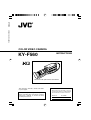
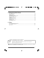
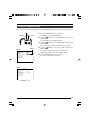
KY-F560
COLOR VIDEO CAMERA
INSTRUCTIONS
For Customer Use:
Enter below the Serial No. which is
located on the bottom of cabinet. Retain
this information for future reference.
Model No. KY-F560U
Serial No.
Thank you for purchasing this JVC product.
Before operating this unit, please read the
instructions carefully to ensure the best
possible performance.
This instruction manual is made from 100%
recycled paper.
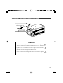
*Illustration with optional lens attachment.
LWT0163-001A
KY-F560
COLOR VIDEO CAMERA
KY-F560
CO
LO
R
VID
EO
CA
M
ER
A

2
1. Read all of these instructions.
2. Save these instructions for later use.
3. All warnings on the product and in the operating instructions should be adhered to.
4. Unplug this appliance system from the wall outlet before cleaning. Do not use liquid cleaners or aerosol
cleaners. Use a damp cloth for cleaning.
5. Do not use attachments not recommended by the appliance manufacturer as they may cause hazards.
6. Do not use this appliance near water – for example, near a bathtub, washbowl, kitchen sink, or laundry
tub, in a wet basement, or near a swimming pool, etc.
7. Do not place this appliance on an unstable cart, stand, or table. The appliance may
fall, causing serious injury to a child or adult, and serious damage to the appliance.
Use only with a cart or stand recommended by the manufacturer, or sold with the
appliance.
Wall or shelf mounting should follow the manufacturer’s instructions, and should
use a mounting kit approved by the manufacturer.
An appliance and cart combination should be moved with care. Quick stops,
excessive force, and uneven surfaces may cause the appliance and cart combination
to overturn.
8. Slots and openings in the cabinet and the back or bottom are provided for ventilation,
and to insure reliable operation of the appliance and to protect it from overheating,
these openings must not be blocked or covered. The openings should never be blocked by placing the
appliance on a bed, sofa, rug, or other similar surface. This appliance should never be placed near or
over a radiator or heat register. This appliance should not be placed in a built-in installation such as a
bookcase unless proper ventilation is provided.
9. This appliance should be operated only from the type of power source indicated on the marking label. If
you are not sure of the type of power supplied to your home, consult your dealer or local power company.
For appliance designed to operate from battery power, refer to the operating instructions.
10. This appliance system is equipped with a 3-wire grounding type plug (a plug having a third (grounding)
pin). This plug will only fit into a grounding-type power outlet. This is a safety feature. If you are unable to
insert the plug into the outlet, contact your electrician to replace your obsolete outlet. Do not defeat the
safety purpose of the grounding plug.
11. For added protection for this product during a lightning storm, or when it is left unattended and unused
for long periods of time, unplug it from the wall outlet and disconnect the antenna or cable system. This
will prevent damage to the product due to lightning and power-line surges.
12. Do not allow anything to rest on the power cord. Do not locate this appliance where the cord will be
abused by persons walking on it.
13. Follow all warnings and instructions marked on the appliance.
14. Do not overload wall outlets and extension cords as this can result in fire or electric shock.
15. Never push objects of any kind into this appliance through cabinet slots as they may touch dangerous
voltage points or short out parts that could result in a fire or electric shock. Never spill liquid of any kind
on the appliance.
16. Do not attempt to service this appliance yourself as opening or removing covers may expose you to
dangerous voltage or other hazards. Refer all servicing to qualified service personnel.
17. Unplug this appliance from the wall outlet and refer servicing to qualified service personnel under the
following conditions:
a. When the power cord or plug is damaged or frayed.
b. If liquid has been spilled into the appliance.
c. If the appliance has been exposed to rain or water.
d. If the appliance does not operate normally by following the operating instructions. Adjust only those
controls that are covered by the operating instructions as improper adjustment of other controls may
result in damage and will often require extensive work by a qualified technician to restore the appliance
to normal operation.
e. If the appliance has been dropped or the cabinet has been damaged.
f. When the appliance exhibits a distinct change in performance – this indicates a need for service.
18. When replacement parts are required, be sure the service technician has used replacement parts specified
by the manufacturer that have the same characteristics as the original part. Unauthorized substitutions
may result in fire, electric shock, or other hazards.
19. Upon completion of any service or repairs to this appliance, ask the service technician to perform routine
safety checks to determine that the appliance is in safe operating condition.
S3125A

3
CAUTION
RISK OF ELECTRIC SHOCK
DO NOT OPEN
CAUTION: TO REDUCE THE RISK OF ELECTRIC SHOCK,
DO NOT REMOVE COVER (OR BACK).
NO USER-SERVICEABLE PARTS INSIDE.
REFER SERVICING TO QUALIFIED SERVICE PERSONNEL
ATTENTION
RISQUE D’ELECTROCUTION
NE PAS OUVRIR
ATTENTION: POUR EVITER TOUT RISQUE D’ELECTROCUTION
NE PAS OUVRIR LE BOITER.
AUCUNE PIECE INTERIEURE N’EST
A REGLER PAR L’UTILISATEUR.
SE REFERER A UN AGENT QUALIFIE EN CAS DE PROBLEME.
Le symbole de l’éclair à l’intérieur d’un triangle équila-
téral est destiné à alerter l’utilisateur sur la présence
d’une “tension dangereuse” non isolée dans le boîtier
du produit. Cette tension est suffisante pour provoquer
l’électrocution de personnes.
Le point d’exclamation à l’intérieur d’un triangle équi-
latéral est destiné à alerter l’utilisateur sur la présence
d’opérations d’entretien importantes au sujet desquel-
les des renseignements se trouvent dans le manuel
d’instructions.
*Ces symboles ne sont utilisés qu’aux Etats-Unis.
The lightning flash with arrowhead symbol, within an
equilateral triangle, is intended to alert the user to the
presence of uninsulated “dangerous voltage” within the
product’s enclosure that may be of sufficient magnitude
to constitute a risk of electric shock to persons.
The exclamation point within an equilateral triangle is
intended to alert the user to the presence of important
operating and maintenance (servicing) instructions in
the literature accompanying the appliance.
INFORMATION
This equipment has been tested and found to comply with
the limits for a Class B digital device, pursuant to Part 15
of the FCC Rules. These limits are designed to provide
reasonable protection against harmful interference in a
residential installation. This equipment generates, uses,
and can radiate radio frequency energy and, if not installed
and used in accordance with the instructions, may cause
harmful interference to radio communications. However,
there is no guarantee that interference will not occur in a
particular installation.
If this equipment does cause harmful interference to radio
or television reception, which can be determined by turning
the equipment off and on, the user is encouraged to try to
correct the interference by one or more of the following
measures:
● Reorient or relocate the receiving antenna.
●
Increase the separation between the equipment and receiver.
●
Connect the equipment into an outlet on a circuit
different from that to which the receiver is connected.
● Consult the dealer or an experienced radio/TV
technician for help.
CAUTION
CHANGES OR MODIFICATIONS NOT APPROVED BY
JVC COULD VOID USER’S AUTHORITY TO OPERATE
THE EQUIPMENT.
NOTE:
The rating plate (serial number plate) is on the bottom of the unit.
WARNING:
TO REDUCE THE RISK OF FIRE OR
ELECTRIC SHOCK, DO NOT EXPOSE THIS
APPLIANCE TO RAIN OR MOISTURE.
This unit should be used with 12 V DC only.
CAUTION:
To prevent electric shocks and fire hazards, DO
NOT use any other power source.
THIS DEVICE COMPLIES WITH PART 15 OF THE FCC
RULES. OPERATION IS SUBJECT TO THE FOLLOW-
ING TWO CONDITIONS: (1) THIS DEVICE MAY NOT
CAUSE HARMFUL INTERFERENCE, AND (2) THIS
DEVICE MUST ACCEPT ANY INTERFERENCE
RECEIVED, INCLUDING INTERFERENCE THAT MAY
CAUSE UNDESIRED OPERATION.
AVERTISSEMENT:
POUR EVITER LES RISQUES D’INCENDIE
OU D’ELECTROCUTION, NE PAS EXPO-
SER L’APPAREIL A L’HUMIDITE OU A LA
PLUIE.
Cet appareil ne doit être utilisé sur 12 V en
courant continu.
ATTENTION:
Afin d’éviter tout resque d’incendie ou
d’électrocution, ne pas utiliser d’autres sources
d’alimentation électrique.
REMARQUE:
La plaque d’identification (numéro de série) se
trouve sur la partie inférieure de l’appareil.
Cet appareil numérique de la Class B est
conforme à la norme NMB-003 du Canada.
This Class B digital apparatus complies with
Canadian ICES-003.
INFORMATION (F0R CANADA)
RENSEIGNEMENT (POUR CANADA)
SAFETY PRECAUTIONS

4
1. Getting Started
Features ............................................................................................................................................... 6
Points to Note During Use .................................................................................................................... 7
Part Names and Functions ................................................................................................................... 8
Description of Terminals ..................................................................................................................... 11
2. Preparation Before Shooting
Basic System ...................................................................................................................................... 12
Applied System ................................................................................................................................... 13
Mounting the Lens .............................................................................................................................. 14
Connecting the Power Supply ............................................................................................................ 15
Mounting the Camera ......................................................................................................................... 16
Precautions to Prevent Camera From Falling .................................................................................... 17
3. Setting and Adjustment During Shooting
External Monitor Adjustment .............................................................................................................. 18
Back Focus Adjustment ...................................................................................................................... 19
White Balance Adjustment ................................................................................................................. 20
White Shading Adjustment ................................................................................................................. 22
4. Various Modes of Shooting
Shooting the Computer Monitor .......................................................................................................... 24
Output of Negative Image ................................................................................................................... 25
White Spot Correction ........................................................................................................................ 26
Thank you for purchasing this product.
These instructions are for KY-F560U.
Contents

5
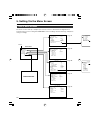
5. Setting Via the Menu Screen
Flow of Menu Screens ........................................................................................................................ 28
Setting Procedures ............................................................................................................................. 30
“EXPOSURE” Screen ......................................................................................................................... 31
“ADVANCED EXPOSURE” Screen .................................................................................................... 33
“WHITE BALANCE” Screen................................................................................................................ 34
“PROCESS (1/2)” Screen ................................................................................................................... 36
“PROCESS (2/2)” Screen ................................................................................................................... 38
“MATRIX ADJUST” Screen ................................................................................................................ 40
“SYSTEM” Screen .............................................................................................................................. 41
“FILE MANAGE” Screen ..................................................................................................................... 42
6. Others
Connecting the Remote Control Unit .................................................................................................. 44
Connecting Optional Devices ............................................................................................................. 46
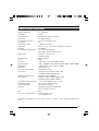
Specifications ..................................................................................................................................... 46
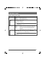
Notations and Symbols Used in This Manual
Caution
Note
☞
Precautions during operation are stated.
Restrictions of functions and specifications are stated for reference purposes.
Indicates the page and item to refer to.
All product names in this manual are trademarks or registered trademarks of their respective companies.
Marks such as ™, ® and © are not used in this manual.

6
Features
● Supersensitive and high-performance camera that realizes a horizontal resolution of 850 lines and F13/
2000 lx via three and a half inch CCD and 12-bit DSP processing.
Enables camera control and hence offers a wide range of uses via use of cameras for high resolution
monitoring, relay, data transmission, weddings and conventions with a swivel base.
● Miniature Camera that Employs Bayonet Mount
Employment of bayonet mount and 1/2-inch color separation optics, and compact design through high-
density mounting of the newly developed IC.
● Automatic Switching between Internal Sync/External Sync
Employs automatic switching between internal/external sync, which is useful for switching between mul-
tiple cameras or system upgrade via connection with other devices.
● SMPTE-compliant Built-in Color Bars Generator
Color monitor can be adjusted with ease with the use of SMPTE color bars.
● Variable Scan Shutter
Eliminates flicker when shooting screen pictures other than NTSC, such as computer screens.
● Equipped with White Shading Function
Corrects color shading triggered by optical characteristics.
● Black Stretch/Black Compress Feature
Stretches or compresses the gain of the dark section in an image to adjust the tone of that section.
● Negative
Used for special purposes such as shooting using films.
● AE (Automatic Exposure)
5 selectable modes in the AE area that are useful when there is a difference in brightness between the
object and its surroundings.
In addition, exposure settings can also be performed according to shooting conditions via selection of AE
level adjustment or photometry detection.
● Built-in White Spot Correction Feature
● Equipped with Remote Terminal
Supports remote control via the remote control unit (sold separately).
● Equipped with Expansion Slot
System upgrade via connection of optional devices (sold separately) is possible.
1.Getting Started

7
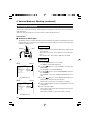
Points to Note During Use
• For important shootings, perform trials in advance to ensure that they are properly recorded.
• We will not compensate for contents lost due to the malfunction of this unit.
Characteristic CCD Phenomena
• Smear and Blooming
When shooting a bright light source, the CCD may induce white streaks (smear) in the vertical direc-
tion of the light source. When the light source is extremely bright, light of the surroundings may
expand (blooming).
• Aliasing
Note that a jagged effect may occur when shooting striped patterns or lines.
• White spot
Operating this unit under a high temperature may give rise to white spots in the image. Ensure to use
this unit within the specified range (–5˚C to 40˚C).
This unit comes with the white spot correction feature that helps to reduce this phenomenon.
☞ Page 26
Precautions During Handling
• Strong Electromagnetic Waves or Magnetism
When placed near radios or TV transmitters, or transformers and monitors that emit strong magne-
tism, noise or color change may occur in the image. Ensure that this unit is kept away from the above
during use.
• Compatible Lens ☞ Page 14 ‘Mounting the Lens’
Lens mount of this unit makes use of bayonet mount and there are restrictions on the type of lens to
be used.
Pay attention to their performance and dimensions when lenses other than those specified are used.
• Cleaning the Body of this Unit (Turn off the power before cleaning.)
Wipe using a soft cloth.
Do not wipe with thinner or benzene. These may corrode or tarnish the surface.
When it is extremely dirty, wipe using a neutral detergent diluted with water, follow by wiping with a
dry cloth.
• When not in use, turn off the power of the system to reduce power consumption.
• Do not mount unit at locations that emit radiation, X-rays or corrosive gases.

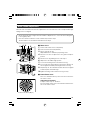
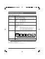
8
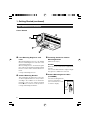
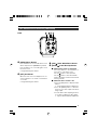
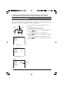
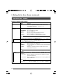
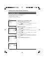
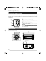
3 Fastening Screws for Camera
Mounting Bracket
(M2.6 x 6 mm, 3 pcs)
Caution
Make sure to use screws that are supplied with
this unit.
Use of screws that are 6 mm or longer in length
may give rise to malfunction of the unit.
4 Camera Mounting Screw Holes
(1/4-20UNC)
Use when mounting this unit
to fixer or swivel bases.
(Use screws that are 7 mm
or shorter in length.)
1 Lens Mounting Ring/Lens Lock
Lever
When dismounting the lens, do so by holding
the lens and turning the lens lock lever in the
anti-clockwise direction.
When mounting the lens, check that the guide
pins of the lens are aligned, followed by turning
the lens lock lever in the clockwise direction to
fasten.
☞ Page 14 ‘Mounting the Lens’
2 Camera Mounting Bracket
This is attached to the bottom face of the cam-
era when supplied. Mount it to the top surface
according to the conditions of use. Mount the
fastening screws for the camera mounting
bracket 3 to the screw holes on the top surface.
☞ Page 16 ‘Mounting the Camera’
Part Names and Functions
Front / Bottom
1. Getting Started (continued)
KY-F560
COLO
R VIDEO CAM
ERA
4
1
2
3
7mm
and
below

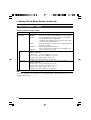
9
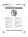
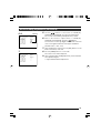
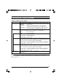
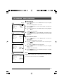
5 [MENU] Menu Button
Press this button for 1-2 seconds. Menu screen
will be output from the [VIDEO OUT] terminal.
Press the button for 1-2 seconds again to clear
the menu screen.
☞ Page 30 ‘Setting Procedures’
6 [SET] Set Button
When the menu screen is displayed, use it to
select a submenu or to confirm a selected item
or set value.
☞ Page 30 ‘Setting Procedures’
Back
7 [AW/ ] Auto White/Down Button
8 [BARS/ ] Color Bars/Up Button
When menu screen is displayed
Press these buttons to move between se-
lection items on the menu screen.
Use the [ ] button to move upwards.
Use the [ ] button to move downwards.
Used for altering the set values when an item
is being selected.
When the menu screen is off
● Press the [AW] button to adjust the white
balance.
☞ Page 20 ‘White Balance Adjustment’
● Press the [BARS] button to switch be-
tween the color bars output and camera
image output.
● Use this button when adjusting the moni-
tor or when recording color bars signal.
☞ Page 18 ‘External Monitor Adjustment’
Part Names and Functions (continued)
5 87 6
MENU
AW
BARS
SET
LENS
REMOTE
GENLOCK IN
VIDEO OUT
POWER
DC IN
SEE INSTRUCTION MANUAL

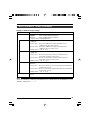
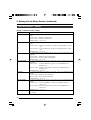
10
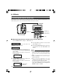
9 [REMOTE] Remote Terminal
(Mini DIN 6 Pin, Female)
Terminal for connection to remote control unit
(RM-LP55 or RM-LP57, both sold separately).
☞ Page 11 ‘Description of Terminals’
☞ Page 44 ‘Connecting the Remote Control
Unit’
0 [LENS] Lens Connection Terminal
Connect the lens cable.
☞ Page 11 ‘Description of Terminals’
☞ Page 14 ‘Mounting the Lens’
! [VIDEO OUT] Video Signal Output
Terminal
Output terminal for composite video signals.
Connect to video input terminals such as moni-
tors or switchers.
@ [POWER] Power Indicator Light
Lights up when power is supplied to this unit.
Part Names and Functions (continued)
1. Getting Started (continued)
# [DC IN] Power Input Terminal
(Mini DIN 8 Pin, Female)
Power of this unit (DC 12 V) is supplied through
this terminal.
Use an AC adaptor (AA-P700) for the power
supply.
☞ Page 11 ‘Description of Terminals’
☞ Page 15 ‘Connecting the Power Supply’
$
[GENLOCK IN] External Sync Signal
Input Terminal
Reference signal input terminal for synchroni-
zation with this unit.
Inputs composite video signals or black burst
signals.
% Slot Cover for Option Cards
Remove the cover to install the option card.
☞ Page 46 ‘Connecting Optional Devices’
Please consult your JVC-authorized dealer on
optional devices.
Back
11
10
12
MENU
AW
BARS
SET
LENS
REMOTE
GENLOCK IN
VIDEO OUT
POWER
DC IN
SEE INSTRUCTION MANUAL
13
15
14
9

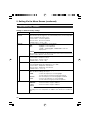
11
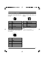
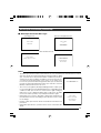
Description of Terminals
Power Input Terminal (Mini DIN 8 Pin,
Female)
Remote Terminal (Mini DIN 6 Pin,
Female)
Lens Connection Terminal (Metal 12
Pin, Female)
Notes
• Please consult your JVC-authorized dealer on
connection of remote terminals.
• Ensure to use cables that are shielded.
1
4
3
6
7
8
5
2
6
7
8
2
1
9
3
4
12
5
10
11
1
3
5
6
4
2
Pin No.
1
2
3
4
5
6
Signal
GND
OPERATE (L:ON)
GND
SID2(TX)
SID1(RX)
+ 9 V Output
Pin No.
1
2
3
4
5
6
7
8
9~12
Signal
LENS RET
NC
GND
LENS AUTO
IRIS CONTROL
+ 12 V Output
IRIS POSITION
IRIS A/R
NC
Pin No.
1
2
3
4
5
6
7
8
Signal
NC
GND
NC
NC
GND
+ 12 V Input
NC
+ 12 V Input

12
ECE-R22
8P8P
MACRO
MACRO
VC-P893
PC
MENU
AW
BARS
SET
LENS
REMOTE
GENLOCK IN
VIDEO OUT
POWER
DC IN
SEE INSTRUCTION MANUAL
AC ADAPTER AA-P700
ON
OFF
POWER
AC120 V
(FUJINON)
RMD-10
RMD-20
(CANON)
TCR-101F
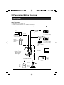
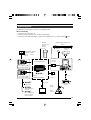
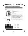
2. Preparation Before Shooting
Basic System
Sync Signals
(Composite Video
Signals or Black
Burst Signals)
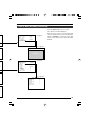
The diagram below illustrates connection of a basic system.
When connecting
• Perform this when the unit is off.
• Read the instruction manual of the unit before performing it.
• Consult your JVC-authorized dealer on details of the equipment in use of cables with the mark.
RS-232C PC
CAMERA CONTROL
REMOTE
CONTROL UNIT
RM-LP55
RM-LP57
LENS CABLE
ZOOM LENS
S17 x 6.6BRM (FUJINON)
YH16 x 7K12U (CANON)
MD ZOOM LENS
S16 x 7.3BMD (FUJINON)
YH16 x 7BKTS (CANON)
MD
CONTROL
CABLE
LENS REMOTE
CONTROL
MONITOR
BNC CABLE
AC POWER ADAPTER
AA-P700
POWER CORD (2 m)
TRIPOD
TP-P300
DOLLY
TP-P205
KY-F560
STANDARD PACKAGE
PAN
AND
TILT
UNIT

13
Applied System
The diagram below illustrates connection of an applied system.
When connecting
• Perform this when the unit is off.
• Read the instruction manual of the unit before performing it.
• Consult your JVC-authorized dealer on details of the equipment in use of cables with the mark.
8P8P
AC
MACRO
MACRO
COLOR VIDEO CAMERA KY-F560
VC-710
(
5 m
)
4P
4P
(FUJINON)
RMD-10
RMD-20
CALLTALLY
INTERCOM
LEVEL
FULL AUTO F1
SHUTTER
GAIN
F2
F3
MENU/SHUTTER GAIN
PAINT AUTO
BR
W.BAL
AUTO
MANU
WHITE MASTER BLACK
POWER
I
O
IRIS
STEP
SHUTTER
MENU
PUSH-ON
DOWN UP
VARIABLE
PUSH-ON
HIGH
LOW
B
A
PRESET
CLOSE OPEN
MID
DOWN UP
F4
BARS
REMOTE CONTROL UNIT RM-P210
INTERCOM
INCOM MIC
INCOM LEVEL
ON
OFF
MAXMIN
DYNAMIC
CARBON
PUSH
CALL
VF
(CANON)
TCR-101F
REMOTE
CONTROL UNIT
RM-LP55
RM-LP57
LENS REMOTE CONTROL
CAMERA REMOTE CONTROL UNIT
RM-P210
HEAD SET
VIEWFINDER
VF-P400
MD ZOOM LENS
S16 x 7.3BMD (FUJINON)
YH16 x 7BKTS (CANON)
ZOOM LENS
S17 x 6.6BRM (FUJINON)
YH16 x 7K12U (CANON)
COLOR VIDEO CAMERA
POWER CORD (2 m)
STUDIO KIT
KA-F5602
KA-F5603
SDI OUTPUT
CARD
KA-F5601
AC POWER ADAPTER
AA-P250
BNC CABLE
TRIPOD
TP-P300
DOLLY
TP-P205
ECE-R22
LENS CABLE
KY-F560
STANDARD PACKAGE
FOCUS MANUAL UNIT
HZ-FM13 (FUJINON)
HZ-FM15 (CANON)
ZOOM SERVO UNIT
HZ-ZS13B
MONITOR

14
2. Preparation Before Shooting (continued)
1.
Loosen by turning the lens lock lever in the anti-clockwise direction.
2.
Mount upon ensuring that the pin and mounting hole of the lens are aligned.
3.
Fasten by turning the lens lock lever in the clockwise direction.
4.
Plug the lens cable into the [LENS] terminal at the back of the unit and ensure that it is locked.
5.
When connecting to the lens remote control, connect the cable (female) for controlling the lens to the
remote control.
Note
When connecting the manual iris lens or lens remote control to operate the lens iris manually, set the “IRIS
MODE” item to “MANUAL”.
☞ Page 31 ‘ “IRIS MODE” Item on “EXPOSURE” Screen’
Caution
• Perform this when the unit is off.
Connecting with the power on may give rise to malfunction of the unit.
• When removing the lens mount cap, ensure that no foreign substances are inside the mount.
• Lenses are not supplied with this unit. Make sure to use lenses that are compatible with this unit.
Mounting the Lens
Follow the procedures below when mounting the auto iris lens.
Refer to the ‘instruction manual’ for the lens and lens remote control as well.
MACRO
4.
3.
5.
MENU
AW
BARS
SET
LENS
REMOTE
GENLOCK IN
VIDEO OUT
POWER
DC IN
SEE INSTRUCTION MANUAL
2.
1.
Compatible MD Zoom Lens
S16 x 7.3 BMD (Fujinon)
YH16 x 7 BKTS (Canon)
Lens
Pin
Hole
Lever for securing the lens
Control Cable
Lock (Female)
Lens Remote
Control
Lens Cable
Lock (Male)
Compatible Lens
Remote Control
(Fujinon)
RMD-10
RMD-20
(Canon)
TCR-101F

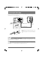
15
Connecting the Power Supply
Connect the [DC IN] terminal at the back of this unit to the [TO CAMERA] terminal of the AC adaptor (AA-
P700) using the power cable supplied (2 m).
Caution
Ensure to make use of AA-P700 for the power supply.
When connecting, ensure that power switch of AA-P700 is turned OFF. Connecting with the power on may
give rise to malfunction of the equipment.
Note
Allow a 10 second interval after switching off the power before turning on again. If the power switch is turned
ON and OFF too soon, malfunctioning such as startup failure may occur.
● Insert plug fully, turn ring and ensure that it is fas-
tened.
Connect the plug in the same way at the AC adaptor's
end.
POWER
DC IN
VIDEO OUTPUT
TO CAMERAS(Y/C) OUTPUT
DC 12V=OUTPUT
EITHER
OUTPUT
MAX 1.25A
SEE INST-
RUCTION
MANUAL
AC 100V
MENU
AW
BARS
SET
LENS
REMOTE
GENLOCK IN
VIDEO OUT
POWER
DC IN
SEE INSTRUCTION MANUAL
AA-P700 AC Adaptor
AC 120 V
[TO CAMERA] Terminal
Power Cable (2 m)
(accessories)
[DC IN]
Terminal
Plug
Ring
White Marking
Connect the end with
white marking to the AC
adaptor.

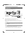
16
Camera Mounting Bracket is mounted to the bottom
surface of the camera when supplied. To mount it to
the top surface, do so by removing the 3 fastening
screws of the camera mounting bracket.
Caution
Make sure to use screws supplied with this unit. Use
of screws that are 6 mm or longer in length may give
rise to malfunction of the unit.
Mounting the Camera
2. Preparation Before Shooting (continued)
• To mount this unit, make use of the screw holes
for mounting the camera on the camera mounting
bracket.
• When mounting this unit, make use of the anti-
rotation hole to prevent it from falling.
<Mounting Procedures>
<Changing the Camera Mounting Bracket>
KY-F560
COLOR VIDEO CAMERA
Screw Hole for Mounting Camera
Anti-rotation Hole
Camera Mounting Bracket

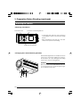
17
Precautions to Prevent Camera From Falling
● Special attention is required when mounting to the wall or ceiling. Get a
contractor to perform the work and avoid doing it on your own. Unit may
fall off and cause injuries or accidents.
● Mount the unit to a secure place using safety cable to prevent it from fall-
ing. To mount, make use of the bracket fastening screw holes on the face
without the camera mounting bracket. (M2.6 x 6 mm)
Pay attention also to the length of the cable.
● Strength of cable to prevent falling of unit shall be at least 10 times greater
than the total mass of the camera and lens.
KY-F560
COLOR VIDEO CAMERA
Safety cable to Prevent
Falling of Equipment
Camera Head
6 mm
Caution

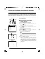
18
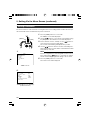
Display the built-in color bars signal at the camera on the monitor to perform color/contrast/brightness
adjustment.
3. Setting and Adjustment During Shooting
External Monitor Adjustment
1.
Connect the color video monitor to the [VIDEO OUT] of this
unit.
2.
Press the [BARS] button to output the color bars signal
(SMPTE-compliant color bars).
3.
With the color bars displayed, turn [BLUE CHECK] at the moni-
tor to ON.
Screen turns into a monochrome of blue and color bars ap-
pear as blue stripes.
4.
Turn the [CHROMA] adjustment knob on the monitor and ad-
just color bars 1 and 8, 7 and $ to the same brightness level.
5.
With [BLUE CHECK] in the ON mode, turn the [PHASE] ad-
justment knob on the monitor to adjust color bars 3 and 0, 5
and @ to the same brightness level.
6.
If brightness of color bars 1 and 8, 7 and $ vary upon [PHASE]
adjustment, repeat chroma adjustment as in step
4.
.
7.
Turn [BLUE CHECK] at the monitor to OFF and return to the
normal screen (R, G and B are all displayed).
8.
Adjust using the [BRIGHT] adjustment knob on the monitor
such that color bars * and ( disappear and ) becomes vis-
ible.
9.
Upon completing the adjustment, press the [BARS] button again
to return to the normal screen.
12345 6 7
890 B C DA
EF G HIJK
2., 9.
[BARS] button
1: White
2: Yellow
3: Cyan
4: Green
5: Magenta
6: Red
7: Blue
8: Blue
9: Black
0: Magenta
!: Black
@: Cyan
#: Black
$: White
%: Black
^: White
&: Black
MENU
AW
BARS
SET
LENS
REMOTE
GENLOCK IN
VIDEO OUT
POWER
DC IN
SEE INSTRUCTION MANUAL
1.
3.~8.

19
Back Focus Adjustment
Zoom Lens
1.
Set iris mode switch of lens to M (manual).
2.
Set zoom mode switch to M (manual).
3.
Turn to open the iris ring.
Adjust illumination to obtain the proper image level.
4.
Turn the zoom lever to adjust lens to the greatest telephoto
position.
5.
Turn the focus ring and align focus on the object.
6.
Adjust lens to the widest angle position.
7.
Loosen the fastening screw for the back focus ring.
8.
Focus on the same object and select a position for which focus
is best aligned, followed by fastening the back focus ring.
9.
Repeat steps
4.
~
8.
for about three times until focus is aligned
for both telephoto and wide angle.
10.
Tighten fastening screw for back focus ring securely.
Power Zoom Lens
There is no manual mode for power zoom lens. Connect the
lens remote control.
Adjustment Procedures
To adjust, follow steps
3.
~
10.
above.
For more details, please refer to the instruction manual for the
lens or lens remote control.
When the lens is mounted for the first time, adjust back focus of the lens if the focus for telephoto/wide angle
during zoom is not aligned.
• Check whether the macro ring has been moved before adjustment. If so, restore the macro fixing knob
to the original position.
• Place the camera at a distance of 3 m or further away from the object.
The best will be to use the Siemens Star Chart as the object.
Siemens Star Chart (Object)
M
RET
WT
A
MACRO
1.
3. 5.
4., 6.
2. 7., 8.,
10.

20
MENU
AW
BARS
SET
LENS
REMOTE
GENLOCK IN
VIDEO OUT
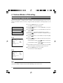
White balance adjustment includes Auto White, Full-time Auto White
(FAW), manual and preset.
Setting procedures for Auto White
(“AUTO1”,“AUTO2”)
1.
Press the [MENU] button for 1-2 seconds.
The “MENU” screen will be displayed.
2.
Use the [ / ] buttons to select “WHITE BALANCE..”, then
press the [SET] button.
The “WHITE BALANCE” screen will be displayed.
3.
Use the [ / ] buttons to select “WHITE BALANCE”, then press
the [SET] button.
The set value displayed will start to blink.
4.
Use the [ / ] buttons to select “AUTO1” or “AUTO2”, then
press the [SET] button.
5.
Press the [MENU] button for 1-2 seconds.
The normal screen will be displayed.
Note
Upon returning to the normal screen, place a white object with
the same illumination conditions as the object, zoom in to the
white portion at the center of the screen (above 80% within the
area).
6.
Press the [AW](Auto White) button.
● When auto white is activated, the auto white operation area
and “AUTO WHITE1 OPERATION” are displayed on the
monitor.
● When white balance is achieved “AUTO WHITE1 OK” will
be displayed for about 3 seconds before returning to the
normal screen.
Color of light (color temperature) may vary with light sources. When light source for illumination of object is
changed, adjust white balance (AUTO WHITE) again. Do not place strong reflectors such as metals near
the object. This may cause error in achieving white balance.
3. Setting and Adjustment During Shooting (continued)
White Balance Adjustment
Auto White Operation
Activated
“WHITE BALANCE” Screen
Auto White Operation Ends
WHIAUTO E1T
RATOPE ION
WHAUTO TIE1
OK
-- ---CE-WHI TE BA LAN
CEBALAN
TPRESE
WH I T E
0
AUTO1
0
LEVEL (R)
LEVEL (B)
LEVEL (R)
LEVEL (G)
LEVEL (B)
SHADING
PAGE BACK
- - - - - -
- - - - - -
- - - - - -
Auto White Operation Area
Set Value
[MENU]
[SET]
[ /AW]
[ ]
Item
Page is loading ...
Page is loading ...
Page is loading ...
Page is loading ...
Page is loading ...
Page is loading ...
Page is loading ...
Page is loading ...
Page is loading ...
Page is loading ...
Page is loading ...
Page is loading ...
Page is loading ...
Page is loading ...
Page is loading ...
Page is loading ...
Page is loading ...
Page is loading ...
Page is loading ...
Page is loading ...
Page is loading ...
Page is loading ...
Page is loading ...
Page is loading ...
Page is loading ...
Page is loading ...
Page is loading ...
Page is loading ...
-
 1
1
-
 2
2
-
 3
3
-
 4
4
-
 5
5
-
 6
6
-
 7
7
-
 8
8
-
 9
9
-
 10
10
-
 11
11
-
 12
12
-
 13
13
-
 14
14
-
 15
15
-
 16
16
-
 17
17
-
 18
18
-
 19
19
-
 20
20
-
 21
21
-
 22
22
-
 23
23
-
 24
24
-
 25
25
-
 26
26
-
 27
27
-
 28
28
-
 29
29
-
 30
30
-
 31
31
-
 32
32
-
 33
33
-
 34
34
-
 35
35
-
 36
36
-
 37
37
-
 38
38
-
 39
39
-
 40
40
-
 41
41
-
 42
42
-
 43
43
-
 44
44
-
 45
45
-
 46
46
-
 47
47
-
 48
48


Ask a question and I''ll find the answer in the document
Finding information in a document is now easier with AI
Related papers
Other documents
-
Toshiba IK-CU43A User manual
-
EVE Outdoor Cam User manual
-
Enduro Engineering 24-1419 User manual
-
Omega FMA2600-SP Owner's manual
-
Enduro Engineering 24-4020 Installation guide
-
 Matrix Orbital EVE2-SHIELD-SPK User manual
-
Sony DXC-990 User manual
-
RED SCARLET-W 5K Monochrome User guide
-
RED WEAPON 6K CF Operating instructions
-
RED WEAPON 8K VV Operating instructions
