Page is loading ...

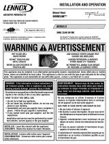
KIT CONTENTS (See Figure 1):
1 ea. Nova SIT NG Regulator Kit (A)
1 ea. #30 NG main burner orifice (42,000 BTU’s) (B)
1 ea. Instruction Sheet
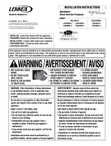
TOOLS NEEDED (See Figure 2):
5/32” Allen Wrench Or T-Handle Wrench
Torx Bit (T20 with 1/4” shank and center hole)
1/2” Open End Wrench
7/16” Open End Wrench
RAVELLE 42™ GAS CONVERSION INSTRUCTIONS LP TO NG
CAT. NO. 75095, MODEL RAVL42-CK-LP TO NG
INSTALLATION INSTRUCTIONS FOR CONVERTING FROM PROPANE GAS (LP) TO
NATURAL GAS (NG). FOR USE WITH THE RAVELLE 42 DIRECT VENT GAS FIREPLACE
775,241M
Rev. A, 08/2008
HEARTH PRODUCTS
KITS AND ACCESSORIES
WARNING
This conversion kit shall be installed by a qualified
service agency in accordance with the manufacturer's
instructions and all applicable codes and requirements
of the authority having jurisdiction. If the information
in these instructions is not followed exactly, a fire,
explosion or production of carbon monoxide may result
causing property damage, personal injury or loss of
life. The qualified service agency performing this
installation is responsible for the proper installation of
this kit and assumes responsibility for this conversion.
The installation is not proper and complete until the
operation of the converted appliance is checked as
specified in the manufacturers instructions supplied
with the kit.
IMPORTANT LE CANADA SEULEMENT
La conversion devra être effectuée conformément
aux recommandations des autorités provinciales
ayant juridiction et conformément aux exigences
du code d'installation CAN/CSA B149.1 .
IMPORTANT CANADA
The conversion shall be carried out in accordance with
the requirements of the provincial authorities having
jurisdiction and in accordance with the requirements
of the CAN/CSA B149.1 Installation code.
AVERTISSEMENT
Cet équipement de conversion sera installé par une
agence qualifiée de service conformément aux instruc-
tions du fabricant et toutes exigences et codes applica-
bles de l'autorisés avoir la juridiction. Si l'information
dans cette instruction n'est pas suivie exactement, un
feu, explosion ou production de protoxyde de carbone
peut résulter le dommages causer de propriété, perte
ou blessure personnelle de vie. L'agence qualifiée de
service est esponsable de l'installation propre de cet
équipment. L'installation n'est pas propre et compléte
jusqu'à l'opération de l'appareil converti est chéque
suivant les critères établis dans les instructions de
propriétaire provisionnées avec l'équipement.
IMPORTANT
The burner orifices provided in this kit are only for
use at elevations of 0 to 2,000 feet (610 M) in the
USA and 0 to 4,500 feet (0-1372 M) in Canada. At
higher elevations the BTU input must be de-rated
by 4% for every 1,000 feet (305 M) to maintain
the proper ratio of gas to air. If the installer must
convert the unit to adjust for varying altitudes, a
deration information sticker must be filled out by the
installer and adhered to the appliance at the time
of the conversion. Contact your local gas supplier
for deration requirements for your area.
D
R
A
F
T
0
8
/
0
6
/
2
0
0
8
A
Fig. 2
Figure 1 - Kit Contents
Figure 2 - Tools Needed
B
TM
1

READ ALL THE STEPS BEFORE STARTING THE CONVERSION.
INSTALLER NOTICE: THESE INSTRUCTIONS MUST BE LEFT WITH
THE APPLIANCE.
This kit contains components required to convert this appliance
from using Propane Gas to using Natural Gas as the only fuel.
All of these components must be replaced in order for the unit to
operate safely on Natural Gas.
When installing gas components use pipe joint compound or
Teflon tape on all pipe fittings before installing (ensure propane
resistant compounds are used, do not use pipe joint compounds
on flare fittings).
INSTALLATION INSTRUCTIONS
TURN OFF THE GAS SUPPLY TO THE APPLIANCE.
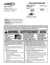
Step 1. Using a Torx T20 or flat screwdriver, remove the Nova SIT LP
Regulator (flame height control) by removing the 3 screws sur-
rounding it (see Figure 3) . Be sure to also remove the LP regulator
diaphragm (see Figure 3).
Step 2. Install the Nova SIT NG Regulator (included in this kit) using the
3 new screws provided as shown in Figure 3.
Diaphragm
Screws
Regulator
Pressure
Regulator
Remove
These
Components
Figure 3
Fill out & affix label from
regulator kit to valve
Step 3 Remove the glass by releasing the two upper spring latches, and
lifting up and out of the lower latches.
Step 4 Remove the right side burner support by removing the four allen
screws (see Figure 4). Note: The right front corner of the burner
shares a screw with the burner support.
Step 5 Remove the allen screw securing the front left corner of the
burner.
Step 6 Move the air shutter control lever all the way to the right (see
Figure 9).
Step 8 Remove the pilot shield by removing the two allen screws (see
Figure 5).
Step 9 Reinstall screws to secure pilot assembly for pilot orifice conver-
sion.
5/32” allen screws
Figure 4
Figure 5
Shared Screw Hole
Step 7 To remove the burner, slide the burner off the orifice and out of
the air shutter by shifting the burner to the right.
Remove the allen
screw securing the
front left corner of
the burner.
Burner
Remove the allen
screws on the right
side of burner.
NOTE: DIAGRAMS AND ILLUSTRATIONS ARE NOT TO SCALE.
2

Step 10 Using a 7/16” open-end wrench, loosen pilot stem a quarter of a
turn to the left, counter-clockwise (see Figure 6).
Step 11 Slide the pilot orifice into the NG position by pushing it toward the
opposite side of the pilot stem. The top side of the orifice slider
should appear silver. The gas supply is now lined up with the NG
pilot orifice (See Figure 7).
Step 12 Tighten the pilot stem by turning it back to the right, making sure
the orifice slider stays pushed into the NG position.
Step 13 IMPORTANT: REINSTALL PILOT SHIELD
Step 14 Using a 1/2” open-end wrench, remove burner orifice (see Figure
8). Replace with #30 NG burner orifice using Teflon pipe sealant
or pipe sealing compound.
Step 15 Install burner, and make sure air shutter is 1/8” open. After Step
14, with the appliance lit and fully warmed up, evaluate the burner
flame appearance and re-adjust air shutter for proper flame ap-
pearance, if necessary.
Figure 6
Figure 8
Figure 7
Figure 9 - Air Shutter
Pilot Stem
Pilot Hood
7/16” Wrench
Slide the pilot
orifice into the NG
position (silver)
Burner Orifice
1/2” End Wrench
Open Close
Expanded
View of Air
Shutter Con-
trol Lever
Air Venturi -
Adjust to 1/8” Gap
Air Shutter
Air Shutter
Control Lever
NOTE: DIAGRAMS AND ILLUSTRATIONS ARE NOT TO SCALE.
3

Step 16. Turn on gas supply and test for gas leaks using a gas leak test
solution (see Test Procedure on Page 22 of the Installation and
Operation Manual).
Step 17. Using a manometer, test the inlet and manifold gas pressure per
instructions in the Installation and Operation Manual (Page 22)
and as shown in the following 2 tables.
Step 18. Reinstall the log set and glass door assembly. See Page 20 (Log
Set Installation) and Page 34 (Door Assembly Installation) in
the Installation and Operation Manual.
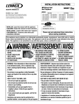
Step 19. Light the appliance per the lighting instructions label on appliance
(located below glass door) or lighting instructions on Page 28 of
the Installation and Operation Manual. Inspect for proper pilot
and burner flame appearances (see Figures 10 and 11). Also
see Flame Color and Behavior and Inspect The Pilot System
For Proper Flame on Page 29 of the Installation and Operation
Manual.
Figure 11 - Burner Flame Appearance
No Blue Flame
Center
Soot at
Flame Tip
Dark Orange
Flame
IMPROPERLY
BURNING FLAME
Soot above
Flame Tip
No Soot at
Flame Tip
PROPERLY
BURNING FLAME
Semi-Transparent
Yellow Flame
Blue Flame
Center
Ports on Pan
Burner Assembly
Figure 10 - Proper Pilot Flame Appearance
Inlet Gas Supply Pressure
Fuel # Minimum Maximum Desired
Nat.
Gas
5" WC/po. C.E
(1.24 kPa)
10.5" WC/po. C.E
(2.61 kPa)
7" WC/po. C.E
(1.74 kPa)
Manifold Gas Supply Pressure
Fuel # Low High
Natural
Gas
(Lo) 1.7" WC/po. C.E
(0.42 kPa)
(Hi) 3.5" WC/po. C.E
(0.87 kPa)
4
Printed in U.S.A. © 2008 Lennox Hearth Products
P/N 775,241M REV. A 08/2008
Lennox Hearth Products reserves the right to make changes at any time, without notice, in
design, materials, specifications, prices and also to discontinue colors, styles and products.
Consult your local distributor for fireplace code information.
NOTE: DIAGRAMS AND ILLUSTRATIONS ARE NOT TO SCALE.
1110 West Taft Avenue • Orange, CA 92865
/