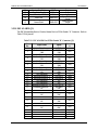
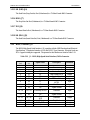
Comtech EF Data DMD50 Operating instructions
- Category
- Networking
- Type
- Operating instructions

Part Number MN-DMD50 Revision 3
Comtech EF Data is an
AS9100 Rev B / ISO9001:2000 Registered Company
IMPORTANT NOTE: The information contained in this document supersedes all previously
published information regarding this product. This manual is subject to change without prior notice.
DMD50
Universal Satellite Modem
Installation and Operation Manual


ER-DMD50.EA2 THIS DOCUMENT IS NOT SUBJECT TO REVISION/UPDATE! PLM CO C-0022887 Page 1 of 2
Errata A
Comtech EF Data Documentation Update
Subject:
Revise “Trademarks” subsection in Preface to include CEFD Patents
and Patents Pending note
Original Manual Part
Number/Rev:
MN-DMD50 Rev 2
Errata Number/
PLM Document ID:
ER-DMD50.EA2
PLM CO Number:
C-0022887
Comments:
The updated information will be incorporated into the next formal
revision of the manual.
Update the manual Preface: Revise the ‘Trademarks’ section to
read (addition in bold):
Trademarks
Product names mentioned in this manual may be trademarks or
registered trademarks of their respective companies and are hereby
acknowledged.
See all of Comtech EF Data's Patents and Patents Pending at
http://patents.comtechefdata.com.

ErrataAforMN‐DMD50Rev2 UpdatePreface
ER-DMD50.EA2 THIS DOCUMENT IS NOT SUBJECT TO REVISION/UPDATE! PLM CO C-0022887 Page 2 of 2
This page is intentionally blank.

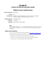
Errata B
Comtech EF Data Documentation Update
DMD50 Universal Satellite Modem
Manual Part Number:
MN-DMD50
Revision:
Rev 3
Errata Subject:
Updates to registered trademarks and licenses for Raytheon Applied
Signal Technology, DoubleTalk and Carrier-in-Carrier
Errata Part Number:
ER-MNDMD50-EB3
CO Number:
C-0023089
Comments:
Attach Errata to Preface, page 1.
Note:
"Applied Signal Technology, Inc." is now "Raytheon Applied Signal Technology". All references
to "Applied Signal Technology, Inc." in this manual are changed to "Raytheon Applied Signal
Technology
".
Patents and Trademarks
See all of Comtech EF Data’s Patents and Patents Pending at http://patents.comtechefdata.com.
Comtech EF Data acknowledges that all trademarks are the property of the trademark owners.
• DoubleTalk
®
is licensed from "Raytheon Applied Signal Technology".
• DoubleTalk
®
is a registered trademark of "Raytheon Applied Signal Technology".
• Carrier-in-Carrier
®
is a registered trademark of Comtech EF Data.

Errata Page 2 of 2
ER-MNDMD50-EB3 THIS DOCUMENT IS NOT SUBJECT TO REVISION/UPDATE. C-0023089
This page is intentionally blank.

Copyright © 2011 Comtech EF Data. All rights reserved. Printed in the USA.
Comtech EF Data, 2114 West 7th Street, Tempe, Arizona 85281 USA, 480.333.2200, FAX: 480.333.2161
DMD50
Universal Satellite Modem
Installation and Operation Manual
Part Number MN-DMD50
Revision 3
January 13, 2011

This page is intentionally blank.

iii
Table of Contents
TABLE OF CONTENTS ............................................................................................................III
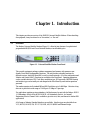
CHAPTER 1. INTRODUCTION .................................................................................. 1–1
1.1 Overview ...................................................................................................................................... 1–1
1.2 8BConfigurations ............................................................................................................................. 1–2
1.2.1 Features/Options Installed at Time of Order ......................................................................... 1–2
1.2.2 Feature Upgrades .................................................................................................................. 1–2
1.2.3 Hardware Options ................................................................................................................. 1–2
1.2.4 Factory Installed Options ...................................................................................................... 1–2
1.3 Function Accessibility ................................................................................................................. 1–2
CHAPTER 2. INSTALLATION ................................................................................... 2–1
2.1 Unpacking and Inspection .......................................................................................................... 2–1
2.2 Installation Requirements .......................................................................................................... 2–2
2.3 Mounting Considerations ........................................................................................................... 2–3
2.4 Initial Configuration Check ....................................................................................................... 2–4
2.5 Modulator Checkout ................................................................................................................... 2–5
2.5.1 Initial Power-Up .................................................................................................................... 2–5
2.5.2 Factory Terminal Setup ......................................................................................................... 2–6
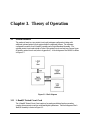
CHAPTER 3. THEORY OF OPERATION .................................................................. 3–1
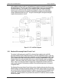
3.1 Modem Hardware ....................................................................................................................... 3–1
3.1.1 L-Band/IF Printed Circuit Card ............................................................................................ 3–1
3.1.2 Baseband Processing Printed Circuit Card ........................................................................... 3–2
3.1.3 Enhanced Interface Printed Circuit Card .............................................................................. 3–3
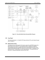
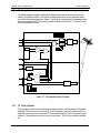
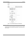
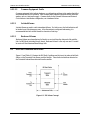
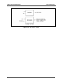
3.2 Functional Block Diagram ......................................................................................................... 3–3
3.2.1 Front Panel ............................................................................................................................ 3–4
3.2.2 Baseband Processing ............................................................................................................. 3–4
3.2.3 Tx Baseband Processing ....................................................................................................... 3–5
3.2.4 Rx Baseband Processing ....................................................................................................... 3–5
3.3 Monitor & Control (M&C) Subsystem ..................................................................................... 3–5
3.3.1 Terminal Port ........................................................................................................................ 3–6
3.3.2 Modem Remote Communications (RLLP) ........................................................................... 3–6
3.3.3 Ethernet M&C Port ............................................................................................................... 3–6
3.3.4 103BModem Monitor Status
......................................................................................................... 3–7

Table of Contents Revision 3
DMD50 Universal Satellite Modem MN-DMD50
iv
3.4 Async Port / ES-ES Communications ....................................................................................... 3–7
3.5 Internal Clock .............................................................................................................................. 3–7
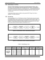
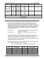
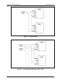
3.6 22BLoopback Features (Terrestrial & IF) ...................................................................................... 3–8
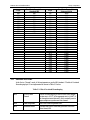
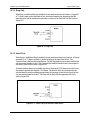
3.7 Clocking Options ....................................................................................................................... 3–11
3.7.1 TX Clock Options ............................................................................................................... 3–11
3.7.1.1 SCTE: Serial Clock Transmit External ........................................................................... 3–12
3.7.1.2 SCT: Serial Clock Transmit ............................................................................................ 3–12
3.7.2 RX Buffer Clock Options ................................................................................................... 3–12
3.7.2.1 RX SAT Clock ................................................................................................................ 3–13
3.7.2.2 SCTE: Serial Clock Transmit External ........................................................................... 3–13
3.7.2.3 SCT: Serial Clock Transmit ............................................................................................ 3–13
3.7.2.4 EXT CLK/EXT BNC: External Clock, J16 .................................................................... 3–13
3.7.2.5 EXT IDI: Insert Data In .................................................................................................. 3–14
3.7.3 EXT REF: External Reference, Top BNC Port, J10 ........................................................... 3–14
3.8 RS530/422/V.35 Interface (Standard) ..................................................................................... 3–14
3.8.1 G.703 Interface (Optional) .................................................................................................. 3–14
3.8.2 HSSI Interface (Optional) ................................................................................................... 3–15
3.8.3 Ethernet Data Interface (Optional) ...................................................................................... 3–15
3.9 Reed-Solomon Codec ................................................................................................................ 3–15
3.9.1 Reed-Solomon Operation .................................................................................................... 3–15
3.9.2 Reed-Solomon Code Rate ................................................................................................... 3–15
3.9.3 Interleaving ......................................................................................................................... 3–16
3.10 Asynchronous Overhead Operation (Framing/Multiplexer Capability) ............................. 3–17
3.11 Standard IBS Mode .................................................................................................................. 3–18
3.12 Asynchronous Multiplexer Mode ........................................................................................... 3–19
3.13 29BESC Backward Alarms ............................................................................................................. 3–19
3.13.1 To Disable the ESC Backward Alarms ............................................................................... 3–20
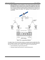
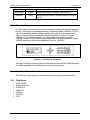
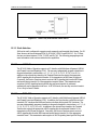
3.14 DoubleTalk Carrier-in-Carrier Option .................................................................................. 3–21
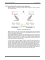
3.14.1 What is DoubleTalk Carrier-in-Carrier? ............................................................................. 3–21
3.14.2 Application Requirements ................................................................................................... 3–22
3.14.3 Operational Recommendations ........................................................................................... 3–24
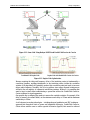
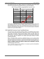
3.14.4 System Functionality and Operational Considerations ....................................................... 3–25
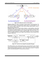
3.14.5 DoubleTalk Carrier-in-Carrier Cancellation Process .......................................................... 3–27
3.14.6 Margin Requirements .......................................................................................................... 3–29
3.14.7 Carrier-in-Carrier Latency .................................................................................................. 3–29
3.14.8 Carrier-in-Carrier and Adaptive Coding and Modulation ................................................... 3–29
3.14.9 Carrier-in-Carrier Link Design ........................................................................................... 3–29
3.14.9.1 Symmetric Data Rate Link .............................................................................................. 3–30
3.14.9.2 Asymmetric Data Rate Link ........................................................................................... 3–33
3.14.9.3 Power Limited Links ....................................................................................................... 3–34
3.14.10 Carrier-in-Carrier Commissioning and Deployment ...................................................... 3–35
3.14.11 Validating Carrier-in-Carrier Performance ..................................................................... 3–36

Table of Contents Revision 3
DMD50 Universal Satellite Modem MN-DMD50
v
3.14.12 Operational References ................................................................................................... 3–37
3.14.13 Carrier-in-Carrier Link Budget Calculation .................................................................... 3–37
3.14.14 Estimating PSD Ratio ..................................................................................................... 3–38
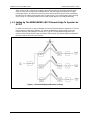
3.14.14.1 Estimating PSD Ratio from LST .................................................................................... 3–38
3.14.14.2 Estimating PSD Ratio from Satmaster ............................................................................ 3–39
3.14.14.3 Estimating PSD Ratio Using Spectrum Analyzer ........................................................... 3–39
3.14.15 DoubleTalk Carrier-in-Carrier Specifications ................................................................. 3–40
3.14.16 Carrier-in-Carrier Summary ............................................................................................ 3–40
3.14.17 Glossary .......................................................................................................................... 3–41
3.15 Satellite Control Channel (SCC) ............................................................................................. 3–43
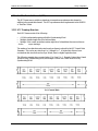
3.15.1 SCC Framing Structure ....................................................................................................... 3–43
3.15.2 115BAggregate Data Rate ........................................................................................................... 3–45
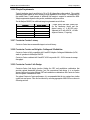
3.15.3 Overhead Rate Comparison ................................................................................................ 3–45
3.15.4 Actual Overhead Rate Calculation ...................................................................................... 3–46
3.15.5 SCC Overhead Channel Setup ............................................................................................ 3–47
3.16 EDMAC Satellite Framing/Deframing Mode ......................................................................... 3–48
3.17 Locating the ID Code Operational Procedure........................................................................ 3–48
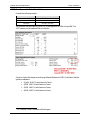
3.18 Strap Codes ................................................................................................................................ 3–48
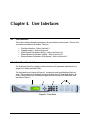
CHAPTER 4. USER INTERFACES............................................................................ 4–1
4.1 User Interfaces ............................................................................................................................ 4–1
4.2 Front Panel User Interface ......................................................................................................... 4–1
4.2.1 LCD Front Panel Display ...................................................................................................... 4–2
4.2.2 Cursor Control Arrow Keys .................................................................................................. 4–2
4.2.3 Numeric Keypad ................................................................................................................... 4–2
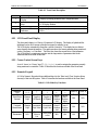
4.2.4 Front Panel LED Indicators .................................................................................................. 4–3
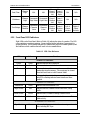
4.3 Parameter Setup .......................................................................................................................... 4–4
4.4 Front Panel Control Screen Menus ........................................................................................... 4–4
4.4.1 Main
Menus .......................................................................................................................... 4–4
4.4.2 Modulator Menu Options and Parameters ............................................................................ 4–5
4.4.3 Demodulator Menu Options and Parameters ...................................................................... 4–11
4.4.4 Interface Menu Options and Parameters ............................................................................. 4–16
4.4.5 Monitor Menu Options and Parameters .............................................................................. 4–21
4.4.6 Alarms Menu Options and Parameters ............................................................................... 4–23
4.4.7 System Menu Options and Parameters ............................................................................... 4–32
4.4.8 Test Menu Options and Parameters .................................................................................... 4–41
4.5 Terminal Mode Control............................................................................................................ 4–42
4.5.1 Modem Terminal Mode Control ......................................................................................... 4–43
4.5.2 Modem Setup for Terminal Mode ...................................................................................... 4–43
4.6 Terminal Port User Interface ................................................................................................... 4–43
4.7 Connecting the Terminal .......................................................................................................... 4–44

Table of Contents Revision 3
DMD50 Universal Satellite Modem MN-DMD50
vi
4.8 Terminal Screens ...................................................................................................................... 4–45
4.9 RS485 Remote Port Interface (RLLP Protocol) ..................................................................... 4–45
4.9.1 Protocol Structure ............................................................................................................... 4–45
4.10 43BEthernet Remote Port Interface (SNMP & Web Browser) ................................................... 4–46
CHAPTER 5. REAR PANEL INTERFACES .............................................................. 5–1
5.1 Connections ................................................................................................................................. 5–1
5.2 Compact Flash ............................................................................................................................. 5–2
5.3 Power Input Modules ................................................................................................................. 5–3
5.3.1 AC Power Input Module ....................................................................................................... 5–3
5.3.2 DC Power Input/Switch ........................................................................................................ 5–3
5.4 Chassis Connections (Standard) ................................................................................................ 5–3
5.4.1 EXT REF (J10) ..................................................................................................................... 5–3
5.4.2 TX IF (J11) ........................................................................................................................... 5–3
5.4.3 TX L-Band IF (J12) .............................................................................................................. 5–3
5.4.4 RX IF (J13) ........................................................................................................................... 5–4
5.4.5 RX L-Band IF (J14) .............................................................................................................. 5–4
5.4.6 ALARM (J15) ....................................................................................................................... 5–4
5.4.7 EXT CLK (J16) ..................................................................................................................... 5–4
5.4.8 143B ASYNC (J17) ....................................................................................................................... 5–5
5.4.9 J18 ......................................................................................................................................... 5–5
5.4.10 EIA-530 (J19) ....................................................................................................................... 5–5
5.4.11 REMOTE (J20) ..................................................................................................................... 5–7
5.4.12 ETHERNET (J21) ................................................................................................................. 5–7
5.5 G.703 IDR/IBS Interface (Optional) ......................................................................................... 5–7
5.6 ESC ALARM (J1) ....................................................................................................................... 5–8
5.7 64K AUDIO (J2) ......................................................................................................................... 5–9
5.8 K DATA (J3) ............................................................................................................................. 5–10
5.9 G.703 BAL (J4) .......................................................................................................................... 5–10
5.9.1 SWITCH INTERFACE (J5) ............................................................................................... 5–11
5.9.2 SD (DDI) (J6) ..................................................................................................................... 5–13
5.9.3 DDO (J7) ............................................................................................................................. 5–13
5.9.4 IDI (J8)
................................................................................................................................ 5–13
5.9.5 SD (IDO) (J9) ..................................................................................................................... 5–13
5.10 Ethernet Data Interface (Optional) ......................................................................................... 5–13
5.11 High-Speed Serial Interface (HSSI) (Optional) ...................................................................... 5–14
5.12 HSSI (J6) .................................................................................................................................... 5–14

Table of Contents Revision 3
DMD50 Universal Satellite Modem MN-DMD50
vii
5.13 ASI/DVB/M2P Interface (Optional) ........................................................................................ 5–15
5.13.1 ASI IN (J1) .......................................................................................................................... 5–15
5.13.2 ASI OUT (J2) ...................................................................................................................... 5–15
5.13.3 DVB/M2P IN (J3) ............................................................................................................... 5–15
5.13.4 DVB/M2P OUT (J4) ........................................................................................................... 5–17
5.14 Ethernet Data Interface (Optional) ......................................................................................... 5–18
5.15 HSSI / G.703 .............................................................................................................................. 5–18
5.15.1 64K AUDIO (J2) ................................................................................................................. 5–19
5.15.2 8K DATA (J3) .................................................................................................................... 5–20
5.15.3 G.703 BAL (J4)................................................................................................................... 5–20
5.15.4 ESC ALARM (J5) ............................................................................................................... 5–21
5.15.5 161BSD (DDI) (J6) ..................................................................................................................... 5–22
5.15.6 162BDDO (J7) ............................................................................................................................. 5–22
5.15.7 IDI (J8) ................................................................................................................................ 5–22
5.15.8 SD (IDO) (J9) ..................................................................................................................... 5–22
5.16 HSSI / Ethernet (J1) .................................................................................................................. 5–22
5.17 Ethernet Data Interface ............................................................................................................ 5–23
5.18 GigE Interface ........................................................................................................................... 5–23
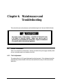
CHAPTER 6. MAINTENANCE AND TROUBLESHOOTING ..................................... 6–1
6.1 Periodic Maintenance ................................................................................................................. 6–1
6.1.1 Clock Adjustment ................................................................................................................. 6–1
6.2 Troubleshooting .......................................................................................................................... 6–2
6.2.1 Alarm Faults .......................................................................................................................... 6–2
6.2.1.1 Major Tx Alarms ............................................................................................................... 6–2
6.2.1.2 Major Rx Alarms .............................................................................................................. 6–3
6.2.1.3 Minor Tx Alarms .............................................................................................................. 6–3
6.2.1.4 Minor Rx Alarms .............................................................................................................. 6–3
6.2.1.5 Drop and Insert Alarms ..................................................................................................... 6–4
6.2.1.6 C
ommon Major Alarms .................................................................................................... 6–4
6.2.2 Alarm Masks ......................................................................................................................... 6–5
6.2.2.1 Active Alarms ................................................................................................................... 6–5
6.2.2.1.1 Major Alarms ....................................................................................................................... 6–5
6.2.2.1.2 Minor Alarms ....................................................................................................................... 6–5
6.2.2.1.3 Common Equipment Faults ................................................................................................. 6–6
6.2.2.2 Latched Alarms ................................................................................................................. 6–6
6.2.2.3 Backward Alarms .............................................................................................................. 6–6
6.3 IBS Fault Conditions and Actions ............................................................................................. 6–6
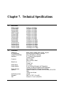
CHAPTER 7. TECHNICAL SPECIFICATIONS .......................................................... 7–1
7.1 Data Rates .................................................................................................................................... 7–1

Table of Contents Revision 3
DMD50 Universal Satellite Modem MN-DMD50
viii
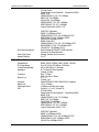
7.2 Modulator .................................................................................................................................... 7–1
7.3 Demodulator ................................................................................................................................ 7–2
7.4 Plesiochronous Buffer ................................................................................................................. 7–3
7.5 Monitor and Control ................................................................................................................... 7–3
7.6 DMD50 Drop and Insert (Optional) .......................................................................................... 7–3
7.7 Terrestrial Interfaces .................................................................................................................. 7–3
7.8 IDR/ESC T2/E2 Interface (Optional) ........................................................................................ 7–3
7.9 IDR/ESC T3/E3/STS1 Interface (Optional) ............................................................................. 7–3
7.10 IBS/Synchronous Interface (Standard) ..................................................................................... 7–4
7.11 High-Speed Serial Interface (HSSI) .......................................................................................... 7–4
7.12 ASI ................................................................................................................................................ 7–4
7.13 DVB/M2P ..................................................................................................................................... 7–4
7.14 Ethernet Data Interface (Optional) ........................................................................................... 7–4
7.15 Gigi Ethernet Data Interface (Optional) ................................................................................... 7–4
7.16 HSSI / G703 T2/E2 Max ............................................................................................................. 7–4
7.17 HSSI / G703 T3/E3/STS1 Max ................................................................................................... 7–4
7.18 HSSI /ETHERNET ..................................................................................................................... 7–5
7.19 Environmental ............................................................................................................................. 7–5
7.20 Physical ........................................................................................................................................ 7–5
7.21 DMD50 Data Rate Limits ........................................................................................................... 7–6
7.21.1 Non-DVB .............................................................................................................................. 7–6
7.21.2 DVB ...................................................................................................................................... 7–8
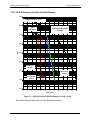
7.22 DMD50 BER Specifications ..................................................................................................... 7–10
7.22.1 BER Performance (Viterbi) ................................................................................................ 7–10
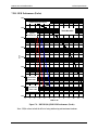
7.22.2 BER Performance (Sequential) ........................................................................................... 7–11
7.22.3 BER Performance (Viterbi with Reed-Solomon) ............................................................... 7–12
7.22.4 BER Performance (Turbo) .................................................................................................. 7–13
7.22.5 BER Performance (8PSK Trellis)
....................................................................................... 7–14
7.22.6 BER Performance (8PSK Turbo) ........................................................................................ 7–15
7.22.7 BER Performance (16QAM Viterbi) .................................................................................. 7–16
7.22.8 BER Performance (16QAM Viterbi with Reed-Solomon) ................................................. 7–17
7.22.9 BER Performance (16QAM Turbo) .................................................................................... 7–18
7.22.10 BER Performance ((O)QPSK Turbo) ............................................................................. 7–19

Table of Contents Revision 3
DMD50 Universal Satellite Modem MN-DMD50
ix
7.22.11 BER Performance (8PSK Turbo) .................................................................................... 7–20
7.22.12 BER Performance (16QAM Turbo) ................................................................................ 7–21
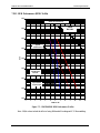
7.22.13 1/2 Rate B/O/QPSK BER Performance (LDPC) ............................................................ 7–22
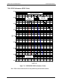
7.22.14 2/3 Rate Q/8PSK/8QAM BER Performance (LDPC) .................................................... 7–23
7.22.15 3/4 Rate Q/8PSK, 8/16QAM BER Performance (LDPC) .............................................. 7–24
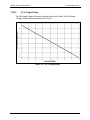
7.22.16 ACG Output Voltage ...................................................................................................... 7–30
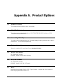
APPENDIX A. PRODUCT OPTIONS .......................................................................... A–1
A.1 Hardware Options ..................................................................................................................... A–1
A.2 G.703/IDR ESC Interface .......................................................................................................... A–1
A.3 Internal High Stability ............................................................................................................... A–1
A.4 DC Input Prime Power .............................................................................................................. A–1
A.5 ASI/RS-422 Parallel ................................................................................................................... A–1
A.6 ASI/LVDS Parallel ..................................................................................................................... A–1
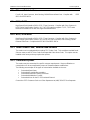
A.7 HSSI ............................................................................................................................................ A–1
A.8 Ethernet Data Interface ............................................................................................................. A–2
A.9 HSSI / G.703 ............................................................................................................................... A–2
A.10 HSSI / ETHERNET ................................................................................................................... A–2
A.11 Turbo Product Code / Variable Reed-Soloman ...................................................................... A–2
A.12 Customized Options ................................................................................................................... A–2
APPENDIX B. FRONT PANEL UPGRADE PROCEDURE ......................................... B–1
B.1 Introduction ................................................................................................................................ B–1
B.2 Required Equipment ................................................................................................................. B–1
B.3 Upgrade Procedure .................................................................................................................... B–1
B.4 Demonstration Procedure ......................................................................................................... B–3
B.4.1 Running in Demonstration Mode ......................................................................................... B–5
B.4.2 Canceling Demonstration Mode .......................................................................................... B–6
APPENDIX C. CARRIER CONTROL ......................................................................... C–1
C.1 States
........................................................................................................................................... C–1
C.2 Carrier Off .................................................................................................................................. C–1
C.3 Carrier On .................................................................................................................................. C–1

Table of Contents Revision 3
DMD50 Universal Satellite Modem MN-DMD50
x
C.4 Carrier Auto ............................................................................................................................... C–2
C.5 Carrier VSat ............................................................................................................................... C–2
C.6 Carrier RTS ................................................................................................................................ C–2
APPENDIX D. WEB BROWSER SETUP GUIDE ...................................................... D–1
D.1 Introduction ................................................................................................................................ D–1
D.2 WEB Users Configuration......................................................................................................... D–2
D.3 Change Web User Name............................................................................................................ D–3
D.4 Change Authentication Password ............................................................................................. D–3
D.5 Change Access Rights ................................................................................................................ D–4
D.6 Modem Web Site ........................................................................................................................ D–4
D.7 Web Page Appearance ............................................................................................................... D–7
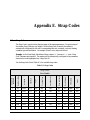
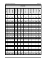
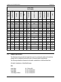
APPENDIX E. STRAP CODES .................................................................................. E–1
E.1 Strap Codes ................................................................................................................................. E–1
E.2 Sample Applications .................................................................................................................. E–5
E.3 Operational Case Examples ...................................................................................................... E–6
E.3.1 Case 1: IDR 8.448 Mbps, 3/4 Rate Viterbi .......................................................................... E–6
E.3.2 Case 2: IBS 1.544 Mbps, 3/4 Rate Viterbi ........................................................................... E–7
E.3.3 Case 3: Closed Network, 3/4 Rate Viterbi, IBS Overhead .................................................. E–8
E.3.4 Case 4: Loop Timing Example ............................................................................................ E–9
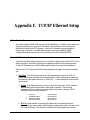
APPENDIX F. TCP/IP ETHERNET SETUP ................................................................ F–1
F.1 Introduction ................................................................................................................................. F–1
F.2 TCP/IP Network Configuration ................................................................................................ F–1
F.3 Network Configuration Summary ............................................................................................. F–3
F.4 Ethernet Test ............................................................................................................................... F–3
F.5 Testing the Ethernet Connection using the Ping Program (Optional) ................................... F–6
APPENDIX G. AUPC OPERATION ............................................................................ G–1
G.1 Automatic Uplink Power Control (AUPC Operation) ........................................................... G–1
G.1.1 Radyne AUPC ...................................................................................................................... G–1
G.1.2 EF AU
PC ............................................................................................................................. G–2

Table of Contents Revision 3
DMD50 Universal Satellite Modem MN-DMD50
xi
G.1.3 Near Side AUPC .................................................................................................................. G–2
APPENDIX H. DROP AND INSERT (D&I) .................................................................. H–1
H.1 Drop and Insert (D&I) ............................................................................................................... H–1
H.1.1 Drop Only ............................................................................................................................ H–3
H.1.2 Insert Only ........................................................................................................................... H–3
H.1.3 Mode Selection .................................................................................................................... H–4
H.1.3.1 PCM-30 ............................................................................................................................ H–4
H.1.3.2 PCM-30C ......................................................................................................................... H–4
H.1.3.3 PCM-31 ............................................................................................................................ H–5
H.1.3.4 PCM-31C ......................................................................................................................... H–5
H.1.3.5 T1-D4/T1-D4-S ................................................................................................................ H–5
H.1.3.6 T1-ESF/T1-ESF-S ............................................................................................................ H–5
H.1.4 Multidestinational Systems .................................................................................................. H–5
H.1.5 Drop and Insert Mapping ..................................................................................................... H–6
H.2 Configuring the Modem for Drop and Insert .......................................................................... H–8
H.2.1 Data Rate .............................................................................................................................. H–8
H.2.2 Operational Network Specification ...................................................................................... H–9
H.2.3 Terrestrial Framing - Drop Mode/Insert Mode .................................................................. H–10
H.2.3.1 Insert Terrestrial Frame Source ...................................................................................... H–10
H.2.4 D&I Sample Configurations and D&I Clock Setup Options ............................................. H–11
H.3 D&I Maps and Map Editing ................................................................................................... H–15
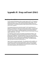
APPENDIX I. EFFCIENT DROP AND INSERT (D&I) ................................................. I–1
I.1 Introduction ................................................................................................................................. I–1
I.2 Prerequisite .................................................................................................................................. I–1
I.3 Efficient Drop & Insert Mode .................................................................................................... I–2
I.3.1 Calculating the Required Satellite Bandwidth ........................................................................... I–3
I.3.2 Calculating the Basic Efficient D&I Rate
.................................................................................. I–3
I.3.3 Calculating the Efficient D&I Rate with E1 Signaling .............................................................. I–3
I.3.4 Calculating the Efficient D&I Rate with Enhanced Asynchronous Overhead .......................... I–4
APPENDIX J. ETHERNET DATA INTERFACE SETUP ............................................. J–1
J.1 Configuring the modem to use the Ethernet Data Interface (Optional) ................................ J–1
J.1.1 Ethernet Flow Control ............................................................................................................... J–1
J.1.1.1 Half-Duplex Flow Control ................................................................................................ J–2
J.1.1.2 Full-Duplex Flow Control ................................................................................................. J–2
J.1.2 Ethernet Daisy Chain ................................................................................................................ J–2
J.1.3 Ethernet QOS Type ................................................................................................................... J–2
J.1.4 Ethernet QOS Queue ................................................................................................................. J–2
J.1.5 Setting Up The DMD20/DMD20 LBST Ethernet Bridge To Operate Like A FIFO............... J–3
J.1.6 Packet Statistics ........................................................................................................................ J–4

Table of Contents Revision 3
DMD50 Universal Satellite Modem MN-DMD50
xii
Notes:

i
PREFACE
About this Manual
This manual describes the installation and operation for the Radyne DMD50. This is a technical
document intended for earth station engineers, technicians, and operators responsible for the
operation and maintenance of the DMD50.
Reporting Comments or Suggestions Concerning this Manual
Comments and suggestions regarding the content and design of this manual will be appreciated.
To submit comments, please contact the Comtech EF Data Technical Publications Department:
TechnicalPublications@comtechefdata.com
Trademarks
Product names mentioned in this manual may be trademarks or registered trademarks of
their respective companies and are hereby acknowledged.
Copyright
2011, Comtech EF Data This manual is proprietary to Comtech EF Data and is
intended for the exclusive use of Comtech EF Data’s customers. No part of this
document may in whole or in part, be copied, reproduced, distributed, translated or
reduced to any electronic or magnetic storage medium without the express written
consent of a duly authorized officer of Comtech EF Data

DMD50 Universal Satellite Modem Revision 3
Preface MN-DMD50
ii
Conventions and References
Related Documents
The following documents are referenced in this manual:
• EN300-421 and EN301-210 ETSI
• ETSI EN302-307
• INTELSAT Earth Station Standards IESS-308, -309, -310, and -315
• EUTELSAT SMS
Metric Conversion
Metric conversion information is located on the inside back cover of this manual. This information is
provided to assist the operator in cross-referencing non-Metric to Metric conversions.
Page is loading ...
Page is loading ...
Page is loading ...
Page is loading ...
Page is loading ...
Page is loading ...
Page is loading ...
Page is loading ...
Page is loading ...
Page is loading ...
Page is loading ...
Page is loading ...
Page is loading ...
Page is loading ...
Page is loading ...
Page is loading ...
Page is loading ...
Page is loading ...
Page is loading ...
Page is loading ...
Page is loading ...
Page is loading ...
Page is loading ...
Page is loading ...
Page is loading ...
Page is loading ...
Page is loading ...
Page is loading ...
Page is loading ...
Page is loading ...
Page is loading ...
Page is loading ...
Page is loading ...
Page is loading ...
Page is loading ...
Page is loading ...
Page is loading ...
Page is loading ...
Page is loading ...
Page is loading ...
Page is loading ...
Page is loading ...
Page is loading ...
Page is loading ...
Page is loading ...
Page is loading ...
Page is loading ...
Page is loading ...
Page is loading ...
Page is loading ...
Page is loading ...
Page is loading ...
Page is loading ...
Page is loading ...
Page is loading ...
Page is loading ...
Page is loading ...
Page is loading ...
Page is loading ...
Page is loading ...
Page is loading ...
Page is loading ...
Page is loading ...
Page is loading ...
Page is loading ...
Page is loading ...
Page is loading ...
Page is loading ...
Page is loading ...
Page is loading ...
Page is loading ...
Page is loading ...
Page is loading ...
Page is loading ...
Page is loading ...
Page is loading ...
Page is loading ...
Page is loading ...
Page is loading ...
Page is loading ...
Page is loading ...
Page is loading ...
Page is loading ...
Page is loading ...
Page is loading ...
Page is loading ...
Page is loading ...
Page is loading ...
Page is loading ...
Page is loading ...
Page is loading ...
Page is loading ...
Page is loading ...
Page is loading ...
Page is loading ...
Page is loading ...
Page is loading ...
Page is loading ...
Page is loading ...
Page is loading ...
Page is loading ...
Page is loading ...
Page is loading ...
Page is loading ...
Page is loading ...
Page is loading ...
Page is loading ...
Page is loading ...
Page is loading ...
Page is loading ...
Page is loading ...
Page is loading ...
Page is loading ...
Page is loading ...
Page is loading ...
Page is loading ...
Page is loading ...
Page is loading ...
Page is loading ...
Page is loading ...
Page is loading ...
Page is loading ...
Page is loading ...
Page is loading ...
Page is loading ...
Page is loading ...
Page is loading ...
Page is loading ...
Page is loading ...
Page is loading ...
Page is loading ...
Page is loading ...
Page is loading ...
Page is loading ...
Page is loading ...
Page is loading ...
Page is loading ...
Page is loading ...
Page is loading ...
Page is loading ...
Page is loading ...
Page is loading ...
Page is loading ...
Page is loading ...
Page is loading ...
Page is loading ...
Page is loading ...
Page is loading ...
Page is loading ...
Page is loading ...
Page is loading ...
Page is loading ...
Page is loading ...
Page is loading ...
Page is loading ...
Page is loading ...
Page is loading ...
Page is loading ...
Page is loading ...
Page is loading ...
Page is loading ...
Page is loading ...
Page is loading ...
Page is loading ...
Page is loading ...
Page is loading ...
Page is loading ...
Page is loading ...
Page is loading ...
Page is loading ...
Page is loading ...
Page is loading ...
Page is loading ...
Page is loading ...
Page is loading ...
Page is loading ...
Page is loading ...
Page is loading ...
Page is loading ...
Page is loading ...
Page is loading ...
Page is loading ...
Page is loading ...
Page is loading ...
Page is loading ...
Page is loading ...
Page is loading ...
Page is loading ...
Page is loading ...
Page is loading ...
Page is loading ...
Page is loading ...
Page is loading ...
Page is loading ...
Page is loading ...
Page is loading ...
Page is loading ...
Page is loading ...
Page is loading ...
Page is loading ...
Page is loading ...
Page is loading ...
Page is loading ...
Page is loading ...
Page is loading ...
Page is loading ...
Page is loading ...
Page is loading ...
Page is loading ...
Page is loading ...
Page is loading ...
Page is loading ...
Page is loading ...
Page is loading ...
Page is loading ...
Page is loading ...
Page is loading ...
Page is loading ...
Page is loading ...
Page is loading ...
Page is loading ...
Page is loading ...
Page is loading ...
Page is loading ...
Page is loading ...
Page is loading ...
Page is loading ...
Page is loading ...
Page is loading ...
Page is loading ...
Page is loading ...
Page is loading ...
Page is loading ...
Page is loading ...
Page is loading ...
Page is loading ...
Page is loading ...
Page is loading ...
Page is loading ...
Page is loading ...
Page is loading ...
Page is loading ...
-
 1
1
-
 2
2
-
 3
3
-
 4
4
-
 5
5
-
 6
6
-
 7
7
-
 8
8
-
 9
9
-
 10
10
-
 11
11
-
 12
12
-
 13
13
-
 14
14
-
 15
15
-
 16
16
-
 17
17
-
 18
18
-
 19
19
-
 20
20
-
 21
21
-
 22
22
-
 23
23
-
 24
24
-
 25
25
-
 26
26
-
 27
27
-
 28
28
-
 29
29
-
 30
30
-
 31
31
-
 32
32
-
 33
33
-
 34
34
-
 35
35
-
 36
36
-
 37
37
-
 38
38
-
 39
39
-
 40
40
-
 41
41
-
 42
42
-
 43
43
-
 44
44
-
 45
45
-
 46
46
-
 47
47
-
 48
48
-
 49
49
-
 50
50
-
 51
51
-
 52
52
-
 53
53
-
 54
54
-
 55
55
-
 56
56
-
 57
57
-
 58
58
-
 59
59
-
 60
60
-
 61
61
-
 62
62
-
 63
63
-
 64
64
-
 65
65
-
 66
66
-
 67
67
-
 68
68
-
 69
69
-
 70
70
-
 71
71
-
 72
72
-
 73
73
-
 74
74
-
 75
75
-
 76
76
-
 77
77
-
 78
78
-
 79
79
-
 80
80
-
 81
81
-
 82
82
-
 83
83
-
 84
84
-
 85
85
-
 86
86
-
 87
87
-
 88
88
-
 89
89
-
 90
90
-
 91
91
-
 92
92
-
 93
93
-
 94
94
-
 95
95
-
 96
96
-
 97
97
-
 98
98
-
 99
99
-
 100
100
-
 101
101
-
 102
102
-
 103
103
-
 104
104
-
 105
105
-
 106
106
-
 107
107
-
 108
108
-
 109
109
-
 110
110
-
 111
111
-
 112
112
-
 113
113
-
 114
114
-
 115
115
-
 116
116
-
 117
117
-
 118
118
-
 119
119
-
 120
120
-
 121
121
-
 122
122
-
 123
123
-
 124
124
-
 125
125
-
 126
126
-
 127
127
-
 128
128
-
 129
129
-
 130
130
-
 131
131
-
 132
132
-
 133
133
-
 134
134
-
 135
135
-
 136
136
-
 137
137
-
 138
138
-
 139
139
-
 140
140
-
 141
141
-
 142
142
-
 143
143
-
 144
144
-
 145
145
-
 146
146
-
 147
147
-
 148
148
-
 149
149
-
 150
150
-
 151
151
-
 152
152
-
 153
153
-
 154
154
-
 155
155
-
 156
156
-
 157
157
-
 158
158
-
 159
159
-
 160
160
-
 161
161
-
 162
162
-
 163
163
-
 164
164
-
 165
165
-
 166
166
-
 167
167
-
 168
168
-
 169
169
-
 170
170
-
 171
171
-
 172
172
-
 173
173
-
 174
174
-
 175
175
-
 176
176
-
 177
177
-
 178
178
-
 179
179
-
 180
180
-
 181
181
-
 182
182
-
 183
183
-
 184
184
-
 185
185
-
 186
186
-
 187
187
-
 188
188
-
 189
189
-
 190
190
-
 191
191
-
 192
192
-
 193
193
-
 194
194
-
 195
195
-
 196
196
-
 197
197
-
 198
198
-
 199
199
-
 200
200
-
 201
201
-
 202
202
-
 203
203
-
 204
204
-
 205
205
-
 206
206
-
 207
207
-
 208
208
-
 209
209
-
 210
210
-
 211
211
-
 212
212
-
 213
213
-
 214
214
-
 215
215
-
 216
216
-
 217
217
-
 218
218
-
 219
219
-
 220
220
-
 221
221
-
 222
222
-
 223
223
-
 224
224
-
 225
225
-
 226
226
-
 227
227
-
 228
228
-
 229
229
-
 230
230
-
 231
231
-
 232
232
-
 233
233
-
 234
234
-
 235
235
-
 236
236
-
 237
237
-
 238
238
-
 239
239
-
 240
240
-
 241
241
-
 242
242
-
 243
243
-
 244
244
-
 245
245
-
 246
246
-
 247
247
-
 248
248
-
 249
249
-
 250
250
-
 251
251
-
 252
252
-
 253
253
-
 254
254
-
 255
255
-
 256
256
-
 257
257
-
 258
258
-
 259
259
-
 260
260
-
 261
261
-
 262
262


Comtech EF Data DMD50 Operating instructions
- Category
- Networking
- Type
- Operating instructions
Ask a question and I''ll find the answer in the document
Finding information in a document is now easier with AI
Related papers
-
Comtech EF Data SDM-300A Operating instructions
-
Comtech EF Data Radyne RCS11 Specification
-
 Radyne Radyne DMD1050 Operating instructions
-
-
-
-
-
-
-

Other documents
-
Promax MO-480, MO-481 Reference guide
-
-
 Radyne DMDVB20 LBST Operating instructions
-
 Paradise Datacom P300-IDR Installation & Operating Handbook
-
 Paradise P300 User manual
-
ADTRAN NxT1 HSSI/V-35 User manual
-
 Paradise P300 User manual
-
Allen-Heath AP4530 User manual
-
Tektronix VITS100 User manual
-
POLYTRON HDM 2 S01 Operating instructions


