INSTALLATION
PAGE 4
ENGLISH
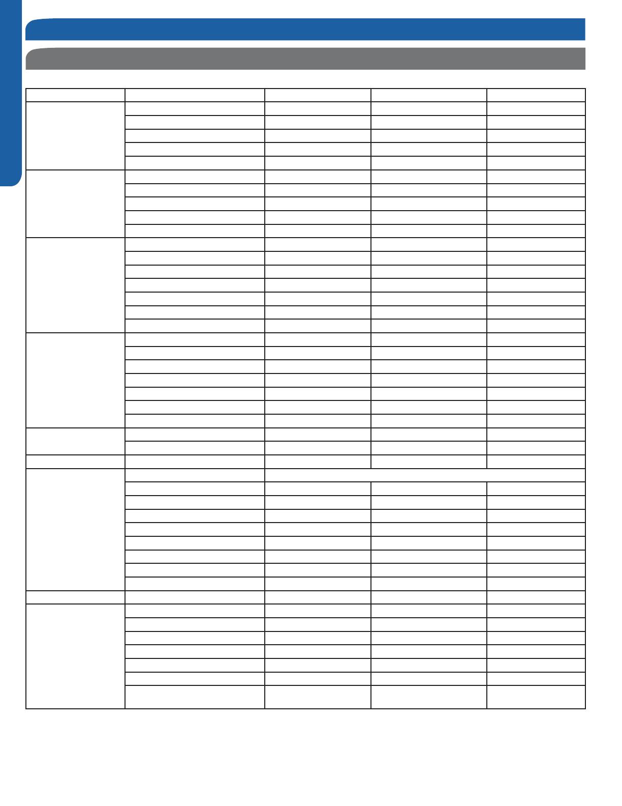
Product Specications
Model Number Outdoor 2U18MS2VHB 3U24MS2VHB 4U36MS2VHB
Cooling Non-ducted
Rated Capacity Btu/hr 17,400 22,500 34,000
Capacity Range Btu/hr 4,400-19,400 5,000-24,500 5,000-36,000
Rated Power Input W 1,650 2,250 3,770
SEER 16.0 18.0 18.0
EER 10.5 10.0 9.0
Cooling Ducted
Rated Capacity Btu/hr 16,500 21,000 31,000
Capacity Range Btu/hr 4,400-19,400 5,000-23,000 5,000-34,000
Rated Power Input W 1,800 2,416 3,590
SEER 15.5 16.0 16.0
EER 8.5 8.5 8.5
Heating Non-ducted
Rated Heating Capacity 47°F Btu/hr 19,100 23,000 34,500
Heating Capacity Range Btu/hr 6,100-22,100 6,100-25,500 6,100-36,500
Rated Power Input W 1,570 1,700 2,650
HSPF 8.6 9.5 9.0
Rated Heating Capacity 17°F Btu/hr 13,000 15,000 22,000
Max. Heating Capacity 17°F Btu/hr 14,000 18,000 26,000
Max. Heating Capacity 5°F Btu/hr 12,000 16,000 24,000
Heating Ducted
Rated Heating Capacity 47°F Btu/hr 18,000 22,000 33,000
Heating Capacity Range Btu/hr 6,100-22,100 6,100-25,000 6,100-35,000
Rated Power Input W 1,700 2,100 3,000
HSPF 8.2 8.5 9.0
Rated Heating Capacity 17°F Btu/hr 10,000 14,000 21,000
Max. Heating Capacity 17°F Btu/hr 12,000 17,000 25,000
Max. Heating Capacity 5°F Btu/hr 10,000 15,000 23,000
Operating Range
Cooling °F(°C) 14~115(-10~46) 14~115(-10~46) 14~115(-10~46)
Heating °F(°C) 5~75(-15~24) 5~75(-15~24) 5~75(-15~24)
Power Supply Voltage, Cycle, Phase V/Hz/- 208-230/60/1 208-230/60/1 208-230/60/1
Outdoor Unit
Compressor Type DC Interver Driven Rotary
Maximum Fuse Size A 25 25 30
Minimum Circuit Amp A 15 18 23
Outdoor Fan Speed RPM 300 ~ 900 300 ~ 900 300 ~ 900
Outdoor Noise Level dB 53 54 56
Dimension: Height in (mm) 27 1/16(688) 28 3/4(730) 33 1/16(840)
Dimension: Width in (mm) 31 7/8(810) 33 7/8(860) 37 5/16(948)
Dimension: Depth in (mm) 11 5/16(288) 12 1/8(308) 13 3/8(340)
Weight (Ship/Net)- lbs (kg) 102.5/95.9(46.5/43.5) 123.4/116.8(56/53) 191.8/167.5(87/76)
Indoor Unit Max Indoor units 2 3 4
Refrigerate Line
Connections Flare Flare Flare
Liquid O.D. in 1/4 1/4 1/4 1/4 1/4 1/4 1/4 1/4 1/4
Suction O.D. in 3/8 3/8 3/8 3/8 3/8 3/8 3/8 3/8 1/2
Factory Charge Oz 49.5 74.0 113.0
Maximum Line Length Ft / m 100/30 200/60 230/70
Maximum Height Ft / m 50/15 50/15 50/15
Maximum Line Length for each indi-
vidual indoor unit Ft / m
82/25 82/25 82/25
Introduction - Overview


