Page is loading ...

DO NOT STORE OR USE
GASOLINE OR OTHER FLAM-
MABLE VAPORS AND LIQUIDS
IN THE VICINITY OF THIS OR
ANY OTHER APPLIANCE.
WHAT TO DO IF YOU SMELL GAS:
• Do not try to light any appliance.
• Do not touch any electric switch;
do not use any phone in your
building.
• Immediately call your gas
supplier from your neighbor’s
phone. Follow the gas suppliers
instructions.
• If you cannot reach your gas
supplier call the fire department.
WARNING!
IF THE INFORMATION IN THIS
MANUAL IS NOT FOLLOWED
EXACTLY, A FIRE OR EXPLO-
SION MAY RESULT CAUSING
PROPERTY DAMAGE, PER-
SONAL INJURY OR LOSS OF
LIFE.
PLEASE READ THIS MANUAL
BEFORE INSTALLING AND
USING APPLIANCE
INSTALLER/CONSUMER
SAFETY INFORMATION
FOR YOUR SAFETY
Installation and service must
be performed by a qualified
installer, service agency or
the gas supplier.
This appliance may be installed in
an after market permanently located
manufactured (mobile) home where not
prohibited by local codes.
This appliance is only for use with the
type of gas indicated on the rating plate.
This appliance is not convertible for use
with other gases unless a certified kit is
used.
Direct Vent / Natural
Vent Gas Heater
Models: 2465, 2466
1935
Dutchwest
gas stove
cover
5/03
Homeowner’s Installation
and Operating Manual
CE RT IFI ED
D
E
S
I
G
N
C
E
R
T
I
F
I
E
D
30001935 1/07 Rev. 11
INSTALLER: Leave this manual with the appliance.
CONSUMER: Retain this manual for future reference.

2
Dutchwest Direct Vent / Natural Vent Gas Heater
30001935
Table of Contents
PLEASE READ THE INSTALLATION & OPERATING INSTRUCTIONS BEFORE USING APPLIANCE.
Thank you and congratulations on your purchase of a Dutchwest stove.
IMPORTANT: Read all instructions and warnings carefully before starting installation. Failure to follow these
instructions may result in a possible fire hazard and will void the warranty.
Installation & Operating Instructions ......................................................................................3
Stove Dimensions .........................................................................................................4
Installation Requirements ..............................................................................................5
Locating the Stove ........................................................................................................
5
Clearance Requirements ..............................................................................................5
Parallel & Corner Installation .........................................................................................
6
Wall and Ceiling Clearances .........................................................................................6
Hearth Requirements ....................................................................................................6
Gas Specifications
.........................................................................................................7
Gas Inlet and Manifold Pressures .................................................................................7
High Elevations .............................................................................................................
7
Horizontal Termination - Direct Vent ONLY ...................................................................7
Vertical Termination - Direct Vent ONLY ........................................................................8
Vent Termination Clearances ........................................................................................
8
General Venting Information - Termination Location ...................................................10
Termination Clearances .............................................................................................. 11
Venting Requirements - Natural Vent ONLY ............................................................... 11
Venting Requirements and Options - Direct Vent ONLY .............................................
12
Install the Optional Fan ...............................................................................................
13
Venting System Assembly - Direct Vent ......................................................................14
Install Vent Adapter Pipe (CFM Vent Components) ....................................................
14
Install Vent Adapter Pipe (Simpson Dura-Vent Components) .....................................15
Side Wall Termination Assembly .................................................................................15
Vent Termination Below Grade ....................................................................................
17
Vertical (Through the Roof) Vent Assembly ................................................................17
Venting System Assembly - Natural Vent ....................................................................
18
Install the Vent Pipe ....................................................................................................18
Install the Log Set .......................................................................................................19
Connect Gas Supply Line ...........................................................................................
19
Burner Information.......................................................................................................20
Air Shutter Adjustment & Instructions ..........................................................................
20
Complete the Assembly ..............................................................................................21
Install ON/OFF Switch .................................................................................................21
Thermostat Connection (Optional) ..............................................................................
22
Install the Front and Top Plates ...................................................................................22
Operation
Your First Fire ..............................................................................................................23
Pilot and Burner Information .......................................................................................23
Flame & Temperature Adjustment / Flame Characteristics .........................................
23
Lighting and Operating Instructions ............................................................................24
Troubleshooting - Honeywell #8420 Gas Control System ...........................................
25
Fuel Conversion Instructions .......................................................................................26
Maintenance
Annual System Inspection ...........................................................................................
29
Logset and Burner/Cleaning and Inspection ...............................................................29
Care of Cast Iron .........................................................................................................
29
Cleaning the Glass ......................................................................................................29
Glass Replacement .....................................................................................................29
Gasket Replacement ...................................................................................................
30
Inspect the Vent System Annually ...............................................................................30
Check the Gas Flame Regularly .................................................................................
30
Stove Disassembly ......................................................................................................30
Wiring Diagram ............................................................................................................31
Replacement Parts .................................................................................................................32
Optional Accessories .............................................................................................................34
Warranty
..................................................................................................................................35
Energuide .................................................................................................................................36

3
Dutchwest Direct Vent / Natural Vent Gas Heater
30001935
General Information
The Dutchwest Direct Vent/Natural Vent Room Heater,
Model Nos. 3070, 3071, 3072 and 3073, is a vented gas
appliance listed to the ANSI standard Z21.88b-2001 and
CSA-2.33b-2001 for Vented Room Heaters, and CSA 2.17-
M91, Gas-Fired Appliances For Use at High Altitudes.
The installation of the Dutchwest Direct Vent/Natural
Vent Room Heater must conform with local codes, or in the
absence of local codes, with National Fuel Gas Code, ANSI
Z223.1/NFPA 54 — latest edition and CSA B-149.1 Instal
-
lation Code. (EXCEPTION: Do not derate this appliance
for altitude. Maintain the manifold pressure at 3.5” w.c. for
Natural Gas and 10.0” w.c. for LP gas at maximum input.)
This appliance is only for use with the type of gas indicat-
ed on the rating plate. This appliance is not convertible for
use with other gases unless a certified kit is used.
Installation and replacement of gas piping, gas utiliza-
tion equipment or accessories, and repair and servicing
of equipment shall be performed only by a qualified
agency. The term “qualified agency” means any individ
-
ual, firm, corporation, or company that either in person
or through a representative is engaged in and is respon-
sible for (a) installation or replacement of gas piping,
or (b), the connection, installation, repair, or servicing
of equipment, who is experienced in such work, familiar
with all precautions required, and has complied with all
the requirements of the authority having jurisdiction.
The Dutchwest Direct Vent/Natural Vent Room Heater
should be inspected before use and at least annually by
a qualified service agency. It is imperative that control
compartments, burners, and circulating air passage-
ways of the appliance be kept clean.
The Dutchwest Direct Vent/Natural Vent Room Heater and
its individual shut-off valve must be disconnected from the
gas supply piping during any pressure testing of that system
at test pressures in excess of 1/2 psig (3.5 kPa).
The Dutchwest Direct Vent/Natural Vent Room Heater
must be isolated from the gas supply piping system by clos-
ing its individual manual shutoff valve during any pressure
testing of the gas supply piping system at test pressures
equal to or less than 1/2 psig.
‘Direct Vent’ describes a sealed combustion system in
which incoming outside air for combustion and outgoing
exhaust enter and exit through two separate concentric
passages within the same sealed vent system. The system
does not use room air to support combustion. The Direct
Vent system permits the gas appliance to be vented directly
to the outside atmosphere through the side of the house or
vertically through the roof. Conventional venting systems
(Natural Vent) take air from the room for combustion and
vent the exhaust vertically through the roof to the atmo-
sphere.
This appliance is approved for bedroom installations in the
U.S. and Canada.
This appliance may be installed in an aftermarket* manu-
factured (mobile) home, where not prohibited by state or
local codes.
WARNING: Operation of this heater when not con
-
nected to a properly installed and maintained venting
system can result in carbon monoxide (CO) poisoning
and possible death.
The Dutchwest Direct Vent/Natural Vent Room Heater,
when installed, must be electrically grounded in accordance
with local codes or, in the absence of local codes, with the
National Electrical Code ANSI/NFPA 70, (latest edition), or of
the current Canadian Electrical Code C22.1.
Due to high temperatures this appliance should be
located out of traffic and away from furniture and drap
-
eries.
WARNING: This appliance is hot while in operation.
Keep children, clothing, and furniture away. Contact
may cause burns or ignition of combustible materials.
Children and adults should be alerted to the hazards
of high surface temperatures and should stay away to
avoid burns or clothing ignition. Young children should
be carefully supervised when they are in the same room
as the appliance.
Clothing or other flammable materials should not be
placed on or near the appliance.
Any safety screen, glass or guard removed for servic-
ing an appliance must be replaced prior to operating the
appliance.
The appliance area must be kept clear and free from
combustible materials, gasoline, and other flammable
vapors and liquids.
The flow of combustion and ventilation air must not
be obstructed. The installation must include adequate
accessibility and clearance for servicing and proper
operation.
WARNING: Do not operate the Room Heater with the
glass panel removed, cracked or broken. Replacement
of the panel should be done by a licensed or qualified
service person.
Do not use this appliance if any part has been under
water. Immediately call a qualified service technician
to inspect the appliance and to replace any part of the
control system and any gas control which has been
under water.
Do not burn wood, trash or any other material for
which this appliance was not designed. This appliance
is designed to burn either natural gas or propane only.
This gas appliance must not be connected to a chim-
ney flue serving a separate solid-fuel burning appliance.
CAUTION: Label all wires prior to disconnection when
servicing controls. Wiring errors can cause improper
and dangerous operation.
Verify proper operation after servicing.
Proposition 65 Warning: Fuels used in gas, woodburn-
ing or oil fired appliances, and the products of combustion of
such fuels, contain chemicals known to the State of Cali-
fornia to cause cancer, birth defects and other reproductive
harm.
California Health & Safety Code Sec. 25249.6
* Aftermarket: Completion of sale, nor for purpose of resale, from
the manufacturer.

4
Dutchwest Direct Vent / Natural Vent Gas Heater
30001935
Dutchwest Direct Vent / Natural Vent Dimensions
C
L
Valve Inlet
23"
(584mm)
6"
(172mm)
24"
(622mm)
C
L
Valve
Inlet
1935
Dutchwest
DV/NV
dimensions
5/15/03
28"
(721mm)
12"
(318mm)
17"
(419mm)
4"
(111mm)
Refer to Page 6 for Flue Collar
Centerline Dimensions
Fig. 1 Dutchwest dimensions.
Attention
The Dutchwest stove is shipped from the factory as a Direct Vent Gas Heater. This heater may be convert-
ed into a Natural Vent unit in the field. If a Natural Vent heater is desired, the Z31D00 FSDHAG Draft Hood
must be directly installed to the top of the unit according to the installation instructions. The Draft Hood
Adapter is available in the 7FSDHASK stove kit or as a separate item.
When the Dutchwest stove is converted to Natural Vent, it uses 4” vent pipe. For aesthetic purposes the
CFM direct vent system may be used up to the ceiling.

5
Dutchwest Direct Vent / Natural Vent Gas Heater
30001935
Installation Requirements
The installation must conform with local codes or, in
the absence of local codes, with the National Fuel Gas
Code, ANSI Z223.1/NFPA 54 - latest edition. (EXCEP-
TION: Do not derate this appliance for altitude. Main-
tain the manifold pressure at 3.5” w.c. for Natural Gas,
and 10” w.c. for Propane).
In Canada, installation must be in accordance with the
current CSA B-149.1 Installation Codes and/or local
codes.
The installation should be done by a qualified ser
-
vice person who is familiar with the building codes
and installation techniques appropriate for your
area to accomplish a safe and effective installation.
Your dealer or your local gas supplier will be able to
refer a qualified service person.
WARNING: Due to high temperatures, the HEATER
should be located out of traffic and away from fur-
niture and draperies.
The surface of the Heater Is hot when it is in use.
Young children should be watched carefully when
they are in the same room when the Heater is in
use, and they should be taught to avoid the hot
surface. Keep any objects that can burn well away
from the Heater, and observe the recommended
clearances that follow.
Locating the Stove
In choosing a location for the stove, consider:
• The location of outside walls;
• Where additional heat is needed:
• Where family members gather most often;
• The vent system requirements.
NOTE: We do not recommend the use of wallpaper
next to this stove. Over time, radiant heat may cause
the wallpaper to shrink, or may adversely affect the
binders in the wallpaper adhesive.
A
B
E
C
D
ST207b
Dutchwest
Stove locations
5/15/03 djt
Direct Vent System Only
A. Flat on corner wall D. Cross Corner
B. Room Divider E. Flat on wall
C. Island
ST207b
Fig. 2 Possible stove locations.
Clearance Requirements
Minimum Clearances to
Combustible Materials
Measure side clearances as shown in Figures 5 and 6
from the outer edge of the cast iron stove top. Measure
rear clearances from the outermost surface of the steel
rear skirt.
The Dutchwest heater is approved for installation into
an alcove constructed of combustible materials to the
dimensions and clearances shown on the next page.
The same clearances apply in a standard parallel instal-
lation.
Warning:
• Always maintain required clear-
ances (air spaces) to nearby combustibles to
prevent fire hazard. Do not fill air spaces with
insulation. All venting components must maintain
a 1” (25mm) clearance to combustible materials.
Maintain a 6” (150mm) clearance when using a
single wall pipe.
• The gas appliance and vent system must be vent
-
ed directly to the outside of the building and never
be attached to a chimney serving a separate solid
fuel or gas-burning appliance. Each direct vent
appliance must use its own separate vent system.
Common vents are prohibited.
• Refer to the manufacturer’s instructions included
with the venting system for complete installation
procedures.

6
Dutchwest Direct Vent / Natural Vent Gas Heater
30001935
Parallel Installation:
Minimum Clearance and Flue Centerline,
Direct Vent and Natural Vent
ST128b
Stardance
flue centerline
9/28/00 djt
C
L
C
L
B
D
C
A
ST128c
Stove Clearances A: 4” (102 mm)
B: 4” (102 mm)
Pipe Centerlines C: 15¹⁄₂” (395 mm)
D: 9” (229 mm)
Fig. 3 Parallel installation, minimum back and side clear-
ances and flue centerlines.
Corner Installation:
Minimum Clearance and Flue Centerline
Direct Vent and Natural Vent
ST129c
Dutchwest
corner specs
5/15/03 djt
A
A
B
B
ST129c
Stove Clearance A: 4” (102 mm)
Pipe Centerline B: 14¹⁄₂” (370 mm)
Fig. 4 Corner installation, minimum corner clearances and
flue centerline.
Wall Centerline from Floor
ST131c
Dutchwest
wall thimble
5/15/03 djt
A
A
Effective Minimum
Wall Thimble 57
¹⁄₂” (1461 mm) (CFM Pipe)
Centerline 53
¹⁄₂” (1359 mm) (Simpson DuraVent Pipe)
ST131c
Fig. 5 Minimum wall thimble centerline.
Wall and Ceiling Clearances
A
C
D
ST101c
Dutchwest
Direct Vent
Min. Clrnc
5/15/03 djt
B
A: Rear Wall 4” (102 mm)
B: Min. Clearance 45¹⁄₂” (1156 mm)*
C: Min. Alcove Height 73¹⁄₂” (1867 mm)*
D: Max. Alcove Depth 48” (1220 mm)
Sidewall Clearance 4” (102 mm)
* needed for installing DuraVent Minimum Vent Kit #2792 or CFM Corpora-
tion Minimum Vent Kit #7TFSDVSK.
ST101c
Fig. 6 Dimensions and clearances to ceiling or alcove.
Hearth Requirements
The Dutchwest Heater must be installed on rigid floor
-
ing. When the heater is installed directly on any com-
bustible surface other than wood flooring, a metal or
wood panel extending the full width and depth of the
unit must be used as the hearth. There are no other
hearth requirements.

7
Dutchwest Direct Vent / Natural Vent Gas Heater
30001935
Max. Min.
Input Input
Model Fuel Gas Control BTU/h BTU/h
2465 Nat Millivolt 28,000 20,000
2466 Prop Millivolt 28,000 19,000
Gas Specifications
Weight: Fully assembled; 202 lbs.
Gas Inlet and Manifold Pressures
Natural LP (Propane)
Inlet Minimum 5.5” w.c. 11.0” w.c.
Inlet Maximum 14.0” w.c. 14.0” w.c.
Manifold Pressure 3.5” w.c. 10.0” w.c.
Dutchwest Direct Vent/Natural Vent
Certified to:
ANSI Z21.88-2005 / CSA 2.33-2005
Vented Gas Fireplace Heaters
The installation of your Dutchwest stove must
conform with local codes, or in the absence of lo-
cal codes, with the National Fuel Gas Code ANSI
Z223.1/NFPA 54 - latest edition, or CSA B149.1
Installation code. (EXCEPTION: Do not derate this
appliance for altitude up to 4,500 feet (1,370m).
Maintain the manifold pressure at 3.5” w.c. for
Natural Gas and 10.0” w.c. for LP Gas.
High Elevations
Input ratings are shown in BTU per hour and are
certified without deration for elevations up to
4,500 feet (1,370m) above sea level.
For elevations above 4,500 feet (1,370m) in USA,
installations must be in accordance with the
current ANSI Z223.1/NFPA 54 and/or local codes
having jurisdiction.
In Canada, please consult provincial and/or local
authorities having jurisdiction for installations at
elevations above 4,500 feet (1,370m).
WARNING: Improper installation, adjustment,
alteration, service or maintenance can cause in-
jury or property damage. Refer to this manual for
correct installation and operational procedures.
For assistance or additional information consult
a qualified installer, service agency, or the gas
supplier.
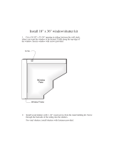
Horizontal Termination -
Direct Vent ONLY
The vent must rise vertically a minimum of 24” (610mm)
off the top of the unit, before the first elbow. The hori-
zontal run may extend up to 20’ (6m) and include a
vertical rise of up to 40’ (12m). (Fig. 7) Horizontal
termination must also meet the criteria shown in Figures
9 through 11.
• Approved vent systems must terminate above and
including the heavy line in Figure 7.
• Two 45˚ elbows may be substituted for each single
90˚ elbow.
• With a rise between 2’ - 5’, one 90˚ or two 45˚ el-
bows may be used.
20
19
18
16
15
14
13
12
11
10
9
8
7
6
5
4
3
2
1
0
1 2 3 4 5 6 7 8 9
10 11 12 13 14 15 16 17 18 19 20
Vertical Run (in feet)
(Measured from the appliance flue collar to the top of the vent pipe.)
Horizontal Run (in feet)
21
22
23
24
25
26
27
28
29
30
31
32
33
34
35
36
37
38
39
40
ST134a
FDV28
Horizontal
vent run
12/3/99 djt
areas modified
1/11/00 djt
ST134a
Fig. 7 Horizontal vent termination window.
May use up to three
90° Elbows
One 90°
Elbow
Unacceptable Venting
Configuration

8
Dutchwest Direct Vent / Natural Vent Gas Heater
30001935
Vertical Termination - Direct Vent ONLY
A vertical vent system must terminate no less than 8’
(2.44m) and no more than 40’ (12m) above the appli-
ance flue collar. A 2¹⁄₄” restrictor plate (supplied) must
be used where specified in all vertically terminated vent
systems. (Fig. 8) NOTE: The restrictor plate supplied
with the vertical termination should be discarded.
Install restrictor plate supplied with stove directly at
stove outlet. A vertically terminated vent system must
also conform to the following criteria:
• No more than three 90˚ elbows may be used.
• Two 45˚ elbows may be substituted for one 90˚
elbow. No more than six elbows may be used.
• Vent must rise a minimum of 2 feet before offset is
used.
• Termination height must conform to roof clearance
as specified in Figure 9.
20
19
18
16
15
14
13
12
11
10
9
8
7
6
5
4
3
2
1
0
20
1 2 3 4 5 6 7 8 9 10 11 12 13 14 15 16 17 18 19
Vertical Run (in feet)
(Measure from the appliance flue collar to the top of the vent pipe.)
Horizontal Run (in feet)
21
22
23
24
25
26
27
28
29
30
31
32
33
34
35
36
37
38
39
40
ST132a
FDV28
Vertical
vent run
12/3/99 djt
area
modified
1/11/00 djt
All Vertical Termina-
tions in this area
Require use of the
2¹⁄₄” Restrictor Plate*
Vertical terminations
must be within this area
Unacceptable Venting
Configuration
No Restrictor Plate
ST132a
Fig. 8 Vertical vent termination window.
*The Restrictor Plate is used on Direct Vent Installations
Only
Vent Termination Clearances
When planning the installation, consider the location
of the vent terminal and clearances. Some of the most
common clearances to keep in mind are shown in Fig-
ure 10.
Important: All vent clearances must be maintained.
Check your vent termination clearances against
Figures 9 through 11.
The vent should be placed so that people cannot be
burned by accidentally touching the vent surfaces when
the stove is operating.
The vent termination should be located where it cannot
be damaged by such things as automobile doors, lawn
mowers or snowblowers and it should be located away
from areas where it could become blocked by snow,
etc.
Some considerations are:
• Obstructions or impediments to venting.
• Nearby combustible materials that could come into
contact with combustion exhaust gases.
• Other nearby openings {within 12” (305mm)} through
which exhaust gas could reenter the building.
• All vegetation within 3’ ((76mm) that may interfere
with the draft.
Other factors that influence where the installation will
be sited include the location of outside walls, where
additional heat may be desired in the home, where the
family members gather most regularly, and perhaps
most importantly, the distance limitations of the venting
system.
IMPORTANT
Direct Vent Only
• The horizontal termination must not be recessed
into the exterior wall or siding.
• Horizontal vent runs must be level toward the vent
termination.
• Clearances around the vent termination must be
maintained.
• For installations using Simpson DuraVent pipe,
parallel installations with minimum wall clearance
have restricted access for connecting the Hori-
zontal Vent Cap straps to the vent pipe. See the
maker’s instructions for recommended installation
procedures.

9
Dutchwest Direct Vent / Natural Vent Gas Heater
30001935
Venting Termination Clearances
Your stove is approved to be vented either through the
side wall, or vertical through the roof.
• This unit does not require any opening for in-
spection of vent pipe.
• Only CFM Corporation and Simpson DuraVent
venting components specifically approved and
labelled for this stove may be used.
• Minimum clearances between vent pipes and
combustible materials is one (1”) inch (25 mm),
except where stated otherwise.
• Venting terminals shall not be recessed into a wall or
siding.
• Horizontal venting must be installed on a level plane
without an inclining or declining slope.
There must not be any obstruction such as bushes,
garden sheds, fences, decks or utility buildings within
24” from the front of the termination hood.
Do not locate termination hood where excessive snow
or ice build up may occur. Be sure to check vent termi-
nation area after snow falls, and clear to prevent ac-
cidental blockage of venting system. When using snow
blowers, make sure snow is not directed towards vent
termination area.
Location of Vent Termination
It is imperative the vent termination be located observ-
ing the minimum clearances as shown on this page.

10
Dutchwest Direct Vent / Natural Vent Gas Heater
30001935
Canadian Installations
1
US Installations
2
V
V
V
V
V
V
V
X
X
X
D
E
B
B
B
C
B
M
B
A
J
K
F
L
VENT TERMINATION AIR SUPPLY INLET
AREA WHERE TERMINAL IS NOT PERMITTED
H
I
Operable
Operable
Fixed
Closed
V
B
CFM145a
DV Termin Location
5/01/01 Rev. 12/05/01
sta
INSIDE
CORNER DETAIL
V
A
G
N
N
CFM145a
General Venting Information - Termination Location
A = Clearance above grade, veranda, porch, 12” (30cm) 12” (30cm)
deck, or balcony
B = Clearance to window or door that may be 6” (15cm) for appliances 6” (15cm) for appliances
opened < 10,000Btuh (3kW), 12” (30cm) < 10,000 Btuh (3kW), 9”
for appliances > 10,000 Btuh (3kW) and (23cm) for appliances > 10,000
< 100,000 Btuh (30kW), 36” (91cm) Btuh (3kW) and < 50,000 Btuh
for appliances > 100,000 Btuh (30kW) (15kW), 12” (30cm) for
appliances > 50,000 Btuh (15kW)
C = Clearance to permanently closed window 12” (305mm) recommended to 12” (305mm) recommended to
prevent window condensation prevent window condensation
D = Vertical clearance to ventilated soffit located
above the terminal within a horizontal 18” (458mm) 18” (458mm)
distance of 2 feet (610mm) from the center
line of the terminal
E = Clearance to unventilated soffit 12” (305mm) 12” (305mm)
F = Clearance to outside corner see next page see next page
G = Clearance to inside corner (see next page) see next page see next page
H = Clearance to each inside of center line 3’ (91cm) within a height of 15’ (5m) 3’ (91cm) within a height of 15’
extended above meter/regulator assembly above the meter/regulator assembly (5m) above the meter/regulator
assy
I = Clearance to service regulator vent outlet 3’ (91cm) 3’ (91cm)
J = Clearance to nonmechanical air supply inlet 6” (15cm) for appliances < 10,000 6” (15cm) for appliances
to building or the combustion air inlet to any Btuh (3kW), 12” (30cm) for < 10,000 Btuh (3kW), 9”
other appliances appliances > 10,000 Btuh (3kW) and (23cm) for appliances > 10,000
< 100,000 Btuh (30kW), 36” (91cm) Btuh (3kW) and < 50,000 Btuh
for appliances > 100,000 Btuh (30kW) (15kW), 12” (30cm) for
appliances > 50,000 Btuh (15kW)
K = Clearance to a mechanical air supply inlet 6’ (1.83m) 3’ (91cm) above if within 10’
(3m) horizontally
L = Clearance above paved sidewalk or paved 7’ (2.13m)† 7’ (2.13m)†
driveway located on public property
M = Clearance under veranda, porch, deck or 12” (30cm)‡ 12” (30cm)‡
balcony
N = Clearance above a roof shall extend a minimum of 24” (610mm) above the highest point when it passes through the roof
surface, and any other obstruction within a horizontal distance of 18” (450mm).
1 In accordance with the current CSA-B149 Installation Codes
2 In accordance with the current ANSI Z223.1/NFPA 54 National Fuel Gas Codes
† A vent shall not terminate directly above a sidewalk or paved driveway which is located between two single family dwellings and
serves both dwellings
‡ only permitted if veranda, porch, deck or balcony is fully open on a minimum 2 sides beneath the floor:
NOTE: 1. Local codes or regulations may require different clearances.
2. The special venting system used on Direct Vent appliances are certified as part of the appliance, with clearances tested and
approved by the listing agency.
3. CFM Corporation assumes no responsibility for the improper performance of the appliance when the venting system does not
meet these requirements.
Fig. 9 Vent termination clearances.

11
Dutchwest Direct Vent / Natural Vent Gas Heater
30001935
Fig. 10 Termination clearances.
Venting Requirements - Natural Vent Only
FP567
NVBR/NVBC VENTING RUNS
11/12/97
Venting Runs
Horizontal Run (in feet)
Vertical Run (in feet)
(Measured from top of the unit before any elbow)
A: Vertical installations up to 36 feet (12m) in
height. Up to an 18 ft. horizontal vent run can be
installed within the vent system using a
maximum of two 90-degree elbows or four
45-degree elbows.
B: Vertical installations up to 36 feet (12m) in
height. Up to a 24 ft. horizontal vent run can be
installed within the vent system using a
maximum of two 45-degree elbows.
(Ratio = 2/3, Hor./Vert.)
= Acceptable venting configuration
= Unacceptable venting configuration
36
34
32
30
28
26
24
22
20
18
16
14
12
10
8
6
4
2
1 2 4 6 8 10 12 14 16 18 20 22 24
A
B
NOTE: When venting staight vertical, without any
elbow, a minimum of 8 ft. vertical is required
off the top of the stove.
FP567b
Fig. 11 Vent termination window - Natural Vent ONLY.
NOTE: When using the FSDHAG, the restrictor
plate supplied with the stove is not used.
Outside Corner
Inside Corner
Termination Clearances
Termination clearances for buildings with combustible and noncombustible exteriors.
G =
Combustible
6" (152 mm)
Noncombustible
2" (51 mm)
F =
Combustible
6" (152 mm)
Noncombustible
2" (51 mm)
G
Balcony -
with no side wall
M =
Combustible &
Noncombustible
12" (305 mm)
M
Balcony -
with perpendicular side wall
M = 24" (610 mm)
P = 20” (508 mm)
M
F
Alcove Applications*
C
D
C
E
V
V
Combustible &
Noncombustible
V
V
V
E = Min. 6” (152 mm) for
non-vinyl sidewalls
Min. 12” (305 mm) for
vinyl sidewalls
O = 8’ (2.4 m) Min.
O
P
584-15
No.
of Caps D
Min.
C
Max.
1 3’ (.9 mm) 2 x D
Actual
2 6’ (1.8 m) 1 x D
Actual
3 9’ (2.7 m) 2/3 x D
Actual
4 12’ (3.7 m) 1/2 x D
Actual
D
Min.
= # of Termination caps x 3
C
Max.
= (2 / # termination caps) x D
Actual
*NOTE: Termination in an alcove space (spaces open only on one side and with an overhang) is permitted with the dimensions
specified for vinyl or non-vinyl siding and soffits. 1. There must be a 3’ (914 mm) minimum between termination caps. 2. All
mechanical air intakes within 10’ (1 m) of a termination cap must be a minimum of 3’ (914 mm) below the termination cap. 3. All
gravity air intakes within 3’ (914 mm) of a termination cap must be a minimum of 1’ (305 mm) below the termination cap.

12
Dutchwest Direct Vent / Natural Vent Gas Heater
30001935
Venting Requirements and Options -
Direct Vent ONLY
Approved Vent System Components
The Dutchwest Heater must be vented to the outdoors
through an adjacent exterior wall or through the roof. The
venting system must be comprised of the appropriate listed
venting components specified on this page. These parts are
available from DuraVent Corporation or your CFM Corporation
Dealer.
Refer to Figure 4 for dimensions relevant to the standard
minimum-vent kits.
Simpson DuraVent Components
Minimum Horizontal Vent Kit 2792
Starter Pipe Assembly
(incl. inner & outer sections) 2768*
90° Elbow, Blk. 990B*
45° Elbow, Gal. 945
6” Straight, Blk. 908B*
9” Straight, Blk. 907B
11” - 14B\,” Adjustable Straight Section 911B
12” Straight 906
24” Straight 904B*
36” Straight 903B
48” Straight 902
Horizontal Vent Cap 984*
Wall Plate 940*
Vinyl Siding Shield 950
Snorkel Termination - 14” 982
Snorkel Termination - 36” 981
Wall Strap 988
Cathedral Ceiling Support Box 941
Storm Collar 953
Firestop Spacer 963
Flashing 0/12 - 6/12 943
Flashing 6/12 - 12/12 943S
Steel Chimney
Kit A 931
Kit B 932
Kit C 933
Masonry Chimney Kit 934
Vertical Termination Cap (High Wind) 991
Vertical Termination Cap (Low Profile) 980
*Included in Minimum Horizontal Vent Kit #2792
All DuraVent Straight vent pipe sections have a net length 1¹⁄₂”
(37mm) less than the nominal dimension; i.e., a 6” (152mm)
Straight pipe section has an effective length of 4
¹⁄₂” (115mm).
CFM Vent Components
The following kits are available to meet the needs of most
installations. All pipe has a 7” outer diameter and includes a
4” diameter inner section. A (CG) designation indicates the
part is finished in Charcoal Gray paint. Consult your dealer
about other vent parts that may be appropriate to complete
the installation.
Min. Through the Wall Vent Kit 7TFSMSK
(1) 90-Degree Elbow (CG)
(1) 24” Straight pipe (CG)
(1) 36” Straight pipe (CG)
(1) Side Wall Termination
(1) Firestop
(1) Zero-clearance sleeve
(1) Hardware package
(1) Finishing plate (CG)
(1) Finishing collar (CG)
(4) Polished Brass flue pipe rings
Through the Wall Vent Kit 7TFSDVSK
(1) 90-Degree Elbow (CG)
(1) 24” Straight pipe (CG)
(1) 48” Straight pipe (CG)
(1) Side Wall Termination
(1) Firestop
(1) Zero-clearance sleeve
(1) Hardware package
(1) Finishing plate (CG)
(1) Finishing collar (CG)
(4) Polished Brass flue pipe rings
Through the Wall Vent Kit for
Below-Grade Termination 7TFSDVSKS
Includes all of the above parts plus
(1) Snorkel Termination
Vertical Termination Kit, 1/12-6/12 Pitch 7TDVSKVA
(1) Combination Horizontal Offset / Roof Support
(1) Vertical Termination
(1) Storm Collar
(1) 1/12-6/12 Flashing
(1) Finishing Plate (CG)
(1) Finishing Collar (CG)
(1) Polished Brass Flue Pipe Ring
(1) Hardware Package
Vertical Termination Kit, 7/12-12/12 Pitch 7TDVSKVB
(1) 7/12 - 12/12 Flashing
and all of the other Vertical Termination parts.
Vertical Termination, Flat Roof 7DVSKVF
(1) Flat Flashing
and all of the other Vertical Termination parts.
Twist Lock 24” Straight Pipe (CG) 7TFSDVP24
(1) 24” Non-adjustable Pipe
(1) Polished Brass Flue Pipe Ring
Twist Lock 48” Straight Pipe (CG) 7TFSDVP48
(1) 48” Nonadjustable Pipe
(1) Polished Brass Flue Pipe Ring
Twist Lock 45-Degree Elbow (CG) 7TFSDVT45
for vertical offsets
(1) 45-degree Elbow
(1) Polished Brass Flue Pipe Ring
Draft Hood Adapter FSDHAG
NV Stove Kit 7FSSK
(1) 7” Diameter Polished Brass Trim Ring
(1) 48” Nonadjustable Pipe (CG)
(1) 24” Nonadjustable Pipe (CG)
(1) Finishing Plate
(1) Finishing Collar (CG)
(1) 90 Degree Elbow (CG)
Stove Kit 7FSDHASK
Includes all parts in the 7FSSK plus the Draft Hood Adapter
FSDHAG
Combination Offset/Roof Support 7DVCS
Attic Insulation Shield 7DVAIS
7” Charcoal Gray Pipe Rings, (4) 7FSDRG
7” Polished Brass Pipe Rings (4) 7FSDRP
Wall Thimble 942G
NOTE: Direct vent pipe may be used on the Natural Vent sys-
tem from the top of the draft hood adapter to the ceiling.

13
Dutchwest Direct Vent / Natural Vent Gas Heater
30001935
Install the Optional Fan
If you are installing the optional convection Fan Kit
#2767 (FK26), continue here. If you are not installing a
Fan Kit, go to Page 14, Venting System Assembly.
1. The fan kit includes a Blower Assembly and a Rheo
-
stat Assembly, connected by a cable. (Fig. 12) The
Blower Assembly mounts to the bottom rear of the
stove, and the Rheostat mounts to the valve cov-
erplate. The assembly includes a ‘snapstat’ which
automatically turns the fan On (or Off) above (or
below) approximately 109˚. The Rheostat also pro-
vides a range of fan speed settings from Off (which
overrides the snapstat function) to High. Unpack and
inspect the Blower assembly. Confirm that the fan
spins freely.
WARNING
This appliance is equipped with a three-prong
(grounded) plug for your protection against shock
hazard and should be plugged directly into a prop-
erly grounded three-prong receptacle. Do not cut or
remove the grounding prong from this plug.
ST473
Fan parts
#2767 FK26
9/29/00
Snapstat
Bracket
Snapstat/
Extension
Assembly
Not Used on RF
Models
Not Used
on
Dutchwest
Blower
Assembly
Connect to PC Board on
RF Models Only
Not Used
on RF
Models
Rheostat
Assembly
ST473
Fig. 12 Fan kit components.
2. Remove the rear skirt insert panel at the bottom of
the Rear Skirt (Fig. 13) and fasten the blower as-
sembly to the firebox back with the two Phillips pan-
head bolts originally installed in the firebox back. (‘1’,
Fig. 14)
3. Attach the snapstat assembly to the snapstat brack-
et with two sheet-metal screws. (‘2’, Fig. 14) Attach
the snapstat bracket to the stove with a hex-head
bolt passing through the bracket and into the stove
base. (‘3’, Fig. 14)
4. The rheostat control switch attaches to the left side
of the valve bracket at the front of the stove.
• Remove retaining nut from shaft of rheostat. (if
preinstalled)
• Insert the rheostat through the hole in the back
of the left side of the valve bracket, aligning the
locator pin with the smaller hole in that bracket.
• Thread the retaining nut onto the shaft of the
rheostat, tightening with a wrench. Do not over-
tighten.
• Attach the control knob to the rheostat shaft.
• Use the wire tie to secure the fan and rheostat
wire harnesses together.
ST757
Dutchwest
rear skirt insert
5/15/03 djt
Rear Skirt
Sheet Metal
Screws
Rear Skirt Insert
ST757
Fig. 13 Remove rear skirt insert.
ST314
Fk26ce
attach fan
1/24/00
Star Washer
Sheet Metal Screws
Phillips
Pan
Head
Bolts
Star
Washer
Snapstat
1/4” - 20
Hex Bolt
Snapstat
Bracket
ST314
1
2
3
Fig. 14 Attach the fan assembly and the snapstat.
ST758
Dutchwest
attach rheostat
5/15/03 djt
Rheostat
Retaining Collar
Rheostat Knob
ST758
Fig. 15 Attach the fan rheostat.

14
Dutchwest Direct Vent / Natural Vent Gas Heater
30001935
Venting System Assembly - Direct Vent
General Information
The Dutchwest is approved for installation only with the
vent components listed on Page 12. Follow the vent
component instructions exactly.
For U.S. installations: The venting system must con-
form with local codes and/or the current National Fuel
Gas Code, ANSI Z223.1/NFPA 54.
For Canadian installations: The venting system must
conform to the current CSA B149.1 installation code.
Install the Vent Adapter Pipe
(CFM Corporation Vent Components)
1. Install the Restrictor Plate. Consult the ‘Vent Run
Specifications’ on Page 8 to determine whether the
restrictor plate is needed. If so, put the restrictor
plate in place within the inner flue collar as shown in
Figure 16.
5. Install the Outer Adapter Pipe. Apply a 1/4” bead
of cement around the inside wall of the pipe, about
1” from the end. Insert the pipe over the stove flue
collar, keeping the vertical seam oriented to the back
of the stove. Also, be sure to align holes on the pipe
with the holes on the flue collar of the firebox. Fasten
the pipe to the holes in the flue collar with the #12 x
1/2” sheet metal screws provided. (Fig. 19)
ST759
Dutchwest
restictor plate
5/15/03
ST759
Fig. 16 Install the restrictor plate only if required for the vent-
ing configuration. Refer to Page 8.
2. Attach Inner Starter Pipe, (found in with the logset),
to the next section of inner pipe.
• Run a bead of sealant about 1/2” from the upper
end of the Inner starter pipe and join the two sec-
tions together.
• Drill three pilot holes into the Inner Starter and
secure the assembly with three sheet metal screws.
(Fig. 17)
3. Dry fit the Outer pipe assembly to the stove for the
purpose of determining the center line of the pipe on
the wall.
• Side Wall Terminations: Dry fit the outer elbow
with the vertical outer vent and confirm the centerline
alignment with the wall thimble opening.
Remove the pipes and elbows before continuing with
Step 4.
4. Attach the Inner Vent Assembly to the stove.
• Run a bead of sealant around the bottom end of
the starter pipe and attach the assembly to the stove
using three 1/4-20 x 3/8” Phillips screws provided in
the parts bag. (Fig. 18)
ST211
attach inner pipe
to next section
12/4/99 djt
CEMENT
First Section of
Vent Pipe
#8 x 1/2” Sheet
Metal Screws
4” Inner
Starter Pipe
ST211
Fig. 17 Connect the inner starter with the next section of in-
ner vent pipe.
ST760
attach inner assy
5/15/0 3 djt
CEMENT
ST760
Fig. 18 Attach inner assembly to flue collar.
ST761
attach inner assy
5/15/03 djt
ST761
Fig. 19 Fasten outer pipe with #12 x 1/2” sheet metal screw.

15
Dutchwest Direct Vent / Natural Vent Gas Heater
30001935
Install the Vent Adapter Pipe
(Simpson Dura-Vent Components)
1. Install the Restrictor Plate. Consult the ‘Vent Run
Specifications’ on Page 8 to determine whether the
restrictor plate is needed. If so, put the restrictor
plate in place within the inner flue collar. (Fig. 16)
2. Discard the inner starter pipe shipped with the log-
set. Using the starter pipe assembly listed on Page
7, slide the inner section out to allow access.
• Run a bead of sealant around the bottom end of
the starter pipe and attach the assembly to the stove
using three 1/4-20 x 3/8” Phillips screws provided in
the parts bag. (Fig. 20)
3. Install the Outer Adapter Pipe. Apply a 1/4” bead
of cement around the outside surface, about one
inch from the crimped end. (Fig. 21) Orient the verti-
cal seam to the rear, and insert the crimped end of
the outer pipe into the flue collar. Fasten with three
sheet metal screws provided.
ST762
dura vent
attach inner assy
5/15/03 djt
CEMENT
1/4-20 x 3/8
Phillips Screws
Inner Adapter
Pipe
ST762
Fig. 20 Simpson DuraVent - install inner adapter pipe.
ST763
DW dura vent
attach outer assy
5/15/03 djt
ST763
Fig. 21 Simpson DuraVent - install outer adapter pipe.
Side Wall Termination Assembly
1. Locate the vent opening on the wall. Refer to Fig-
ure 5, Page 6, to determine the opening centerline.
It may be necessary to first position the stove and
measure to find the hole location. Depending on
whether the wall is made of combustible materials,
cut the opening to the size shown in Figure 22. Com-
bustible wall openings must be framed as shown in
Figure 22.
VO584-100
Vent Opening
2/99 djt
CFM System
9³⁄₈”
(240 mm
Combustible Wall
Framing Detail
10”
(250 mm)
7¹⁄₂”
(191 mm)
9³⁄₈”
(240 mm
10”
(250 mm)
DuraVent
System
VO584-100
Fig. 22 Locate vent opening.
2. Measure the wall thickness and cut the wall sleeve
sections to proper length (MAXIMUM 12”). Assemble
the sleeve with the #8 sheet metal screws supplied.
Attach the firestop plate to the sleeve end with the
holes. (Fig. 23) NOTE: The wall sleeve is required
in combustible walls only.
3. Install the Wall Firestop/Sleeve assembly into the
wall cutout and fasten the firestop to the wall cutout
framing members. (Fig. 23)
ZCS103
Zero Clearance Sleeve
& Firestop
12/6/99 djt
Sleeve
12”
(305 mm)
Max. Length
Firestop
ZCS103
Fig. 23 Assemble the wall sleeve and firestop.

16
Dutchwest Direct Vent / Natural Vent Gas Heater
30001935
For DuraVent pipe only: Install vent pipe by align-
ing the locking system together, sliding the pipes
together and twisting clockwise.
• Install 90° elbow. Twist lock as before.
• Slide the wall plate over horizontal run before at
-
taching the horizontal run to the elbow. Fasten wall
plate to wall.
4. For CFM Vent Pipe only: If necessary, measure
to determine the vertical length (X) of pipe required
from the adapter pipe to the wall cutout centerline,
including a 2” (51mm) overlap at the joint. (Fig.
24) use a hacksaw or tin snips to trim the pipe as
needed.
X
ST764
DW
measure vertical vent
5/15/03 djt
ST764
Fig. 24 Determine the vertical pipe length.
5. Install first the inner then the outer straight pipe
section(s), trimmed end down, to the point of the el-
bow. Drill 3 holes through each joint and fasten with
sheet metal screws.
6. Seal and install the elbow using 3 sheet metal
screws at each joint.
7. Measure, and cut if needed, the appropriate length
of pipe section needed to make the connection
through the wall. Include a 2” overlap; i.e. from the
elbow to the outside wall face, about 2” or the dis-
tance required if installing a second 90° elbow. (Fig.
25)
8. Slip the wall plate and trim collar over the interior
end of the horizontal pipe and install into the wall
sleeve. Seal the joint inside the wall plate if needed
to keep cold air from being drawn into the home.
9. Seal the ends and connect the horizontal pipe to the
elbow. Fasten the wall plate to the pipe with three
sheet metal screws. Slide the trim collar up against
the wall plate to cover the screws. (Fig. 26)
ST215
measure thru wall
12/6/99 djt
ST215
X
Fig. 25 Measure the horizontal length.
ST216
install pipe thru wall
12/6/99 djt
Trim Collar
Wall
Sleeve
Wall Plate
ST216
Fig. 26 Install the horizontal pipe and wall plate parts.
10. For both CFM and DuraVent Systems: Install the
vent terminal. (Fig. 27) Apply high temperature seal-
ant one inch from the ends of the inner and outer
collars. Guide the inner and outer vent termination
collars into the adjacent pipes. Double check that
the vent pipes overlap the collars by 2”. Fasten the
termination to the wall with the screws provided, and
caulk the joint with weatherproof sealant.
11. For CFM only: Install Charcoal Gray Pipe Rings
(#7FSDRG) or Polished Brass Pipe Rings (#7FS-
DRP) at pipe joints, if desired.
ST217
install wall terminal
12/6/99 djt
Seal Both
Terminal Ends
Caulk Plate Joint with
Weatherproof Sealant
ST217
Fig. 27 Install the vent terminal.

17
Dutchwest Direct Vent / Natural Vent Gas Heater
30001935
Vent Termination Below Grade
Install Snorkel Kit #7FSDVSKS when it is not possible
to meet the required vent termination clearances of 12”
(305mm) above grade level. The snorkel kit will allow
installation depth of down to 7” (178mm) below grade
level. The seven inches is measured from the center of
the horizontal vent pipe as it penetrates the wall. If the
venting system is installed below grade, a window
well must be installed with adequate and proper
drainage. (Fig. 28)
NOTE: Be sure to maintain side wall clearances and
vent run restrictions. Refer to Figures 3, 4, 7, and 8.
1. Establish the vent hole through the wall.
2. Remove soil to a depth of approximately 16” (406
mm) below the base of the snorkel. Install a window
well (not supplied). Refill the hole with 12” (305mm)
of coarse gravel and maintain a clearance of at least
4” (102 mm) below the snorkel. (Fig. 28)
3. Install the vent system as described on Pages 14-
17.
4. Be sure to make a watertight joint around the vent
pipe joint at the inside and outside wall joints.
5. Apply high temperature sealant around the inner
and outer snorkel collars. Join the pipes and fasten
the snorkel termination to the wall with the screws
provided.
6. Level the soil to maintain a 4” clearance below the
snorkel.
ST218
install snorkel
12/6/99 djt
Waterproof Seal
Around Pipe
Firestop
Window
Well
Drain
Snorkel
Termination
Cap
4” Clearance
Gravel
ST765
Fig. 28 Snorkel kit installation.
ST219
snorkel detail
12/6/99 djt
Recessed Wall
Firestop
Finishing
Collar
7” Pipe
Wall Plate
Sheet Metal
Screws and
Bracket
Wall Screws
and Anchors
Waterproof
Seal Around
Pipe
ST219
Fig. 29 Use extension brackets to mount snorkel against
recessed wall.
If the foundation is recessed, use extension brackets
(not supplied) to fasten the lower portion of the snorkel.
Fasten the brackets to the wall first, and then fasten
to the snorkel with self-tapping #8 x 1/2” sheet metal
screws. Extend the vent pipes out as far as the protrud-
ing wall face. (Fig. 29)
Vertical (Through the Roof)
Vent Assembly
Note that all vertically terminated installations must in-
clude the restrictor plate included with the stove. Refer
to Figure 8, Page 8.
Make certain the vent system conforms to all other
requirements for vertical termination as specified on
Page 8.
This installation will require you to first determine the
roof pitch and use the appropriate vent components.
Refer to Figures 8 and 9 on Pages 8 and 10.
1. Locate the final position of the stove, observing all
clearances for both the vent and the stove.
2. Plumb to the center of the inner (4”) flue collar from
the ceiling above, and mark that location.
3. Cut the opening:
CFM System: 9³⁄₈” x 9³⁄₈” (240mm x 240mm)
DuraVent System: 10” x 10” (254mm x 254mm)
4. Plumb any additional opening through the roof or
other construction that may be needed. In all cases,
the opening must provide a minimum of 1” (25mm)
clearance to the vent pipe.
5. Place the stove in its final position.
6. Install firestop(s) #7DVFS and Attic Insulation Shield
#7DVAIS as needed. (Fig. 30) If there is a room
above ceiling level, a firestop must be installed on
both the bottom and top sides of the ceiling joists.
If an attic is above ceiling level, an attic insulation
shield must be installed.
7. Install the appropriate roof support and flashing,
making certain that the upper flange of the flashing
base is below the shingles. (Fig. 31)

18
Dutchwest Direct Vent / Natural Vent Gas Heater
30001935
8. Install appropriate pipe sections until the vent run
reaches above the flashing. The enlarged ends of
the vent sections always face downward.
9. Install the storm collar and seal around the joints.
(Fig. 31)
10. Add additional vent lengths to achieve the proper
overall height.
11. Apply cement to the inner and outer termination col
-
lars and install the terminal cap.
ST222
vent thru ceiling
12/99
#7DVAIS
Attic
Insulation
Shield
#7DVFS
Firestop
In Upper
Floor
#7DVFS
Firestop in
Ceiling
Use Four 8d
Nails
ST222
Fig. 30 Install firestops and attic insulation shield.
ST221
vent thru roof
12/99
Storm Collar
Sealant
Upper
edge of
flange goes
under upper
shingles
Flashing
#7DVSKV
(A, B of F)
Roof Support
ST221
Fig. 31 Roof support and flashing.
Venting System Assembly - Natural Vent
General Information
The Dutchwest Heater is shipped from the factory as
a Direct Vent Heater. It may be converted to a Natural
Vent heater by installing the Model Z31D00 FSDHAG
Draft Hood Adapter.
The Dutchwest Heater is approved for installation as
a Natural Vent. CFM Direct Vent pipe could be used
directly after the Draft Hood Adapter up to the ceiling,
then B-vent pipe must be used. Do not mix types of
B-vent pipe; use components from one maker or the
other. Follow the vent component maker’s instructions
exactly. The heater will also accept standard or enam-
elled 7” (150mm) diameter pipe, around the Type B
venting, for decorative purposes only. (Fig. 32)
NOTE: The restrictor plate supplied with the stove
is not used for Natural Vent applications.
ST358
DW
Decorative
pipe around b-vent
5/15/03 djt
Decorative 7”
Pipe
4” B-vent
Pipe
Draft Hood
Adapter
CFM Direct Vent
System may be
used Draft Hood
up up to the ceiling
ST766
Fig. 32 Decorative 7” pipe may be fitted around the B-vent
pipe.
The Dutchwest stove, when installed as a Natural vent
heater, includes a vent safety switch. (Fig. 60, Page
32) Operating the stove when it is not connected to a
properly installed and maintained venting system, or
tampering with or disconnecting the vent safety switch,
can result in carbon monoxide (CO) poisoning and pos-
sible death.
For U.S. installations: The venting system must con-
form with local codes and/or the current National Fuel
Gas Code, ANSI Z22.1.
For Canadian installations: The venting system must
conform to the current CSA B149.1 installation code.
Install the Vent Pipe
Apply a bead of sealant around bottom end of inner
starter pipe (found in bag with logset) and attach to
stove. Apply a bead of sealant around top of inner
starter pipe and install the Z31D00 FSDHAG Draft
Hood according to Draft Hood instructions. (Fig. 33)

19
Dutchwest Direct Vent / Natural Vent Gas Heater
30001935
Attach the first section of venting to the draft hood. De-
pending on the length of the individual venting sections
and the lengths of the decorative pipe (if installed), you
may need to slip the decorative pipe over the venting
sections before attaching upper sections to lower ones.
The sections of decorative pipe should be oriented with
their seams (if any) toward the wall; sections usually
do not need to be fastened at each joint, other than
slip sections. If the layout includes a slip section, this
should be the last section of pipe visible in the room, at
the ceiling. Complete the venting according to the vent
maker’s instructions.
ST767
DW
attach draft hood
5/15/03 djt
CEMENT
ST767
Fig. 33 Install draft hood adapter.
Install the Log Set
1. Remove the logs from their packaging, and inspect
each piece for damage. DO NOT INSTALL DAM-
AGED LOGS.
2. Install the rear log centering it side to side on the
sheet metal shelf at the back of the firebox. (Fig. 34)
The log will touch both sides and the back wall of the
firebox.
3. Install the right log by engaging hole on bottom with
pin on the rear log. (Fig. 34) Then set right bottom
side on the burner so the edge of the log touches the
right side of the firebox. The right log does not use
the locator pins on the burner to stay in place.
4. Install the left log by engaging hole on bottom with
pin on rear log. (Fig. 34) Then set left bottom side
on the burner so the edge of the log touches the left
side of the firebox.
5. Loosely sprinkle the lava rocks directly on top of the
burner in front of and between the decorative grate
and the right and left logs. Use the lava rock to cover
brackets on the burner. (Fig. 35)
LG141
Stardance
Install logs 1
12/1
1/00 djt
Left Log
Right Log
Rear Log
Decorative Grate
LG141
Fig. 34 Install the back, left and right logs.
Connect the Gas Supply Line
Check the Rating Plate attached by a steel cable to the
firebox, to confirm that you have the appropriate firebox
for the type of fuel to be used. The Dutchwest may be
converted from one gas to another using the appropri-
ate Fuel Conversion Kit listed on Page 34.
CAUTION
This appliance should only be connected
by a qualified gas technician. Test to
confirm manifold pressures as specified
below.
The Dutchwest Heater and its individual shutoff
valve must be disconnected from the gas supply
piping during any pressure testing of that system
at test pressures in excess of 1/2 psig (3.5 kPa).
The Dutchwest Heater must be isolated from the
gas supply piping system by closing its individual
manual shutoff valve during any pressure testing
of the gas supply piping system at test pressure
equal to or less than 1/2 psig.
There must be a gas shutoff between the stove
and the supply.
In order to connect Natural Gas, use a fitting with
3/8” NPT nipple on the valve side and 1/2” natural
gas supply line with an input of 28,000 BTUs at a
manifold pressure of 3.5” and minimum inlet sup-
ply for adjustment of 5.5” w.c.
In order to connect Propane, use a fitting with
3/8” NPT nipple on the valve side and 1/2” pro-
pane gas supply line with an input of 28,000 BTUs
at a manifold pressure of 10.0” and minimum inlet
supply for adjustment of 11.0” w.c.

20
Dutchwest Direct Vent / Natural Vent Gas Heater
30001935
In the U.S.; Gas connection should be made in ac-
cordance with current National Fuel Gas Code, ANSI
Z223.1/NFPA 54. Since some municipalities have
additional local codes, be sure to consult your local
authority.
In Canada; consult the local authority and CSA-B149.1
installation code.
Always check for gas leaks with a mild
soap and water solution. Do not use an
open flame for leak testing.
Light the pilot according to the directions on Page 25,
before going to the next step.
Burner Information
The appliance must only use the gas specified on the
rating plate, unless converted using a Fuel Conver-
sion Kit. To convert from LP to Natural Gas use Kit
#000-5021. To convert from Natural Gas to LP use Kit
#000-5022.
Conversion instructions are provided with each kit and
beginning on Page 27 in this manual.
Air Shutter Adjustment Instructions
To adjust the air shutter, the following procedures
should be followed:
1. Remove stove front. Lift stove front up and then
swing bottom out and away to disengage from the
stove body. (Fig. 36)
2. Swing open the swiveling latches at the top left and
right corners of the glass frame. (Fig. 57, Page 31)
This appliance should be connected to the gas
supply only by a qualified gas service technician.
Follow all local codes.
There must be a gas shut-off between the stove
and the supply.
In order to connect Natural Gas, use a fitting with 3/8”
NPT nipple on the valve side and 1/2” natural gas sup-
ply line with an input of 28,000 BTUs at a manifold pres-
sure of 3.5” and minimum inlet supply for adjustment of
5.5” w.c.
In order to connect Propane, use a fitting with 3/8”
NPT nipple on the valve side and 1/2” propane gas
supply line with an input of 28,000 BTUs at a manifold
pressure of 10.0” and minimum inlet supply for adjust-
ment of 11.0” w.c.
Air Shutter Adjustment
The Dutchwest is shipped from the factory with the air
shutter adjusted to the minimum allowed opening. Refer
to Table 1. Based on the altitude where the stove is
located, a shutter adjustment is acceptable to provide a
mixed balance of flame color/glow. To adjust the shutter
opening, follow the steps below.
NOTE: The air shutter may only be adjusted to a more
open position. The factory setting is the minimum allow-
able air shutter opening. (Figs. 38 & 39)
Model Natural Gas LP
Direct Vent 1/2” 1/2”
Natural Vent 1/2” 1”
Table 1. Air Shutter Adjustment
Minimum rear injector inlet openings.
D
UTCH
W
EST
D
UTCH
W
EST
Est. 1974
ST771a
DW
remove
stove front
5/30/03 djt
ST771a
Fig. 36 Remove stove front.
3. Pull the top edge of the glass and frame assembly
away from the firebox, and lift it off its supports on
the bottom of the firebox face. Place the assembly
out of the way on a flat, padded surface such as a
counter protected by a towel.
4. Take the logset out of the firebox if previously in-
stalled.
5. Remove the rear log bracket by unfastening the
screw. (Fig. 37)
6. Remove the right and left log bracket assembly by
unfastening the two screws which hold the burner in
place. (Fig. 37)
7. Hold the burner at the right hand side and lift to clear
the right burner leg. Then pull to the right to clear the
injectors on the left hand side.
ST350
Jefferson
air shutter adj
3/20/00 djt
Remove Screws
Rear Log Bracket
Pilot
Left & Right Log
Bracket Assembly
ST768
Fig. 37 Remove rear log bracket and left and right log
bracket assembly.
/