Roberts Gorden 350 User manual
- Category
- Water heaters & boilers
- Type
- User manual

Installation, Operation
& Service Manual
Models UHA[S]
150, 175, 200, 225
250, 300, 350, 400
P/N 111101NA 06/08 Rev. E
UHA-Series
Tubular Unit Heaters
(Standard Range)
WARNING
FOR YOUR SAFETY
If you smell gas:
1. Open windows.
2. DO NOT try to light any appliance.
3. DO NOT use electrical switches.
4. DO NOT use any telephone in
your building.
5. Leave the building.
6. Immediately call your local gas
supplier after leaving the building.
Follow the gas suppliers
instructions.
7. If you cannot reach your gas
supplier, call the Fire Department.
Fire Hazard
Do not store or use gasoline or other
flammable vapors and liquids in the
vicinity of this or any other appliance.
Some objects will catch fire or explode
when placed close to heater.
Failure to follow these instructions can
result in death, injury or property
damage.
WARNING
Installation must be done by a contractor qualified
in the installation and service of gas-fired heating
equipment or your gas supplier.
Improper installation, adjustment, alteration, service
or maintenance can result in death, injury or property
damage. Read the Installation, Operation and Service
Manual thoroughly before installing or servicing
this equipment.
Installer
Please take the time to read and understand
these instructions prior to any installation.
Installer must give a copy of this manual to the owner.
Owner
Keep this manual in a safe place in order to provide
your serviceman with necessary information.
Roberts-Gordon LLC
1250 William Street
P. O. Box 4 4
Buffalo, New York 14240-0044
Telephone: 716.852.4400
Fax: 716.852.0854
Toll Free: 800.828.7450
www.rg-inc.com
© 2008 Roberts-Gordon LLC
Quality in Any Language™
Combat
®


© 2008
Roberts-Gordon LLC
All rights reserved. No part of this work covered by the copyrights herein may be reproduced
or copied in any form or by any means - graphic, electronic, or mechanical, including
photocopying, recording, taping or information storage and retrieval systems - without the
written permission of Roberts-Gordon LLC.
Printed in U.S.A.
TABLE OF CONTENTS
SECTION 1: Heater Safety...................................................... 1
1.1 Manpower Requirements ............................................. 1
SECTION 2: Installer Responsibility .....................................2
2.1 Wall Tag .......................................................................2
2.2 Corrosive Chemicals....................................................2
2.3 National Standards and Applicable Codes ..................2
SECTION 3: Critical Considerations .....................................3
3.1 Basic Information.........................................................3
3.2 Location and Suspension ............................................ 3
3.3 Minimum Required Installation Clearances .................3
3.4 Clearances to Combustibles ........................................3
3.5 Ventilation .................................................................... 3
3.6 Gas Supply ..................................................................3
3.7 Electrical Supply ..........................................................3
3.8 Vent.............................................................................. 3
3.9 Separated Combustion Installation .............................. 3
SECTION 4: National Standards and Applicable Codes .....5
4.1 Gas Codes...................................................................5
4.2 Aircraft Hangars ...........................................................5
4.3 Parking Structures and Repair Garages...................... 5
4.4 Electrical ......................................................................5
4.5 Venting......................................................................... 5
4.6 High Altitude ................................................................ 5
SECTION 5: Major Components ............................................ 6
5.1 General........................................................................ 6
5.2 Suspension..................................................................6
SECTION 6: Venting................................................................ 7
6.1 Venting......................................................................... 7
6.2 Vent Installation ...........................................................7
6.3 Unvented Operation..................................................... 8
6.4 Horizontal Venting........................................................ 8
6.5 Vertical Venting............................................................8
6.6 Length Requirements ..................................................8
6.7 Vent Material................................................................ 9
SECTION 7: Air Supply......................................................... 13
7.1 Separated Combustion Installation............................. 13
7.2 Unvented Installation.................................................. 13
7.3 Building Ventilation ..................................................... 13
7.4 Outside Combustion Air Supply.................................. 13
SECTION 8: Gas Piping........................................................ 14
8.1 Connections............................................................... 14
SECTION 9: Wiring................................................................ 15
9.1 Positioning Thermostats ............................................ 15
9.2 Low Voltage Thermostat with One Heater ................. 15
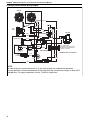
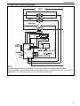
9.3 UHA[S] Series Internal Wiring Diagram..................... 16
9.4 UHA[S] Series Ladder Wiring Diagram...................... 17
9.5 Electrical Connection to the Heater ........................... 18
SECTION 10: Operation and Maintenance.......................... 19
10.1 Pre-Start-Up Checks ................................................ 19
10.2 Begin Start-Up ......................................................... 19
10.3 Complete the Start-Up .............................................21
SECTION 11: User Instructions............................................22
11.1 User Instructions.......................................................22
11.2 Heater Operation ......................................................22
11.3 Lighting Instructions..................................................22
11.4 Simple Troubleshooting.............................................22
SECTION 12: Servicing.........................................................24
12.1 Servicing Instructions...............................................24
12.2 Burner Maintenance.................................................24
12.3 Fan/Motor Assembly Maintenance...........................24
12.4 Heat Exchanger Maintenance..................................24
12.5 Gas Valve Maintenance ...........................................24
12.6 Flue Blower ..............................................................24
12.7 Venting and Air Intake Pipe......................................24
12.8 Maintenance Checklist .............................................25
SECTION 13: Troubleshooting .............................................27
13.1 General ....................................................................27
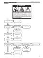
13.2 Troubleshooting For Automatic Ignition
Burner Systems .......................................................28
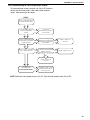
13.3 Troubleshooting for Flame Supervision System .......29
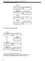
13.4 Troubleshooting for Gas Valves................................30
13.5 Troubleshooting for Flue Blower...............................30
SECTION 14: Replacement Parts.........................................31
14.1 Gas Valve.................................................................31
14.2 Burner Compartment ...............................................32
14.3 Ignition Electrode and Flame Probe .........................33
14.4 Heat Exchanger .......................................................34
14.5 Louvers and Louver Spring ......................................34
14.6 Flue Blower .............................................................35
14.7 Pressure Switch........................................................36
14.8 Ignition Control .........................................................36
14.9 Axial Fan/Guard/Motor Assembly.............................36
14.10 Limit Switches ........................................................37
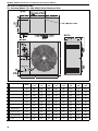
SECTION 15: Specifications.................................................38
15.1 Standard (Models 150 - 400) UHA[S] Series
Dimension Data .......................................................38
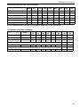
15.2 General Technical Data Table (All Models) ..............39
15.3 Technical Data Table (All Models) ............................39
SECTION 16: The ROBERTS GORDON
®
COMBAT
®
UHA-Series Warranty .....................................41


TABLE OF FIGURES
Figure 1: Installation Clearances and Clearances
to Combustibles ......................................................... 4
Figure 2: Suspension Methods .................................................6
Figure 3: Vent and Roof Detail .................................................. 9
Figure 4: Standard Vented Heater - Vertical
and Horizontal Vent Termination................................9
Figure 5: Standard Vented Heater - Common
Vertical Vent Termination......................................... 10
Figure 6: Separated Combustion Heater - Vertical
and Horizontal Vent Termination.............................. 11
Figure 7: Concentric Vent Box ................................................ 11
Figure 8: Concentric Vertical and Horizontal Vent
Termination - Separated Combustion Heater .......... 12
Figure 9: Gas Connection ....................................................... 14
Figure 10: Automatic Burner Control Sequence...................... 20
Figure 11: Gas Valve for Models UHA[S] 150 - 400 ................ 20
Figure 12: LED Diagnostic Codes...........................................22


SECTION 1: HEATER SAFETY
1
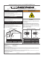
SECTION 1: HEATER SAFETY
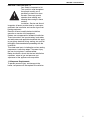
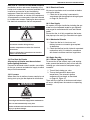
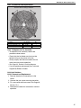
Your Safety is Important to Us!
This symbol is used throughout
the manual to notify you of
possible fire, electrical or burn
hazards. Please pay special
attention when reading and
following the warnings in these
sections.
Installation, Service and Annual
Inspection of heater must be done by a contractor
qualified in the installation and service of gas-fired
heating equipment.
Read this manual carefully before installation,
operation or service of this equipment.
Heaters are not approved for residential installation.
These instructions, the layout drawing, local codes
and ordinances and applicable standards that apply
to gas piping, electrical wiring, venting, etc. must be
thoroughly understood before proceeding with the
installation.
Thin sheet metal parts, including the various venting
components, have sharp edges. To prevent injury,
the use of work gloves is recommended.
Before installation, ch‘eck that the local distribution
conditions, nature of gas and pressure and
adjustment of the appliance are compatible.
1.1 Manpower Requirements
To prevent personal injury and damage to the
heater, two persons will be required for installation.

COMBAT
®
UHA UNIT HEATER INSTALLATION OPERATION AND SERVICE MANUAL
2
SECTION 2: INSTALLER RESPONSIBILITY
The installer is responsible for the following:
• To install the heater, as well as the gas and
electrical supplies, in accordance with applicable
specifications and codes. Roberts-Gordon
recommends the installer contact a Local
Building Inspector or Fire Marshal for guidance.
• To use the information given in a layout drawing
and in the manual together with the cited codes
and regulations to perform the installation.
• To install the heater in accordance with the
clearances to combustibles.
• To furnish all needed materials not furnished as
standard equipment.
• To plan location of supports, vents and air
intakes.
• To provide access for servicing.
• To provide the owner with a copy of this
Installation, Operation and Service Manual.
• To never use heater as support for a ladder or
other access equipment and never hang or
suspend anything from heater.
• To ensure there is adequate air circulation
around the heater and to supply air for
combustion, ventilation and distribution in
accordance with local codes.
2.1 Wall Tag
A laminated wall tag is included with the heater as a
permanent reminder of the safety instructions and
the importance of the required clearances to
combustibles. Affix the tag by peeling off the backing
of the adhesive strips on the rear surface and
position the tag on a wall near the heater.
A copy of the wall tag (P/N 91040031) is illustrated
on the back cover.
Know your model number. Model number is found
on the heater and in the Installation, Operation and
Service Manual. See Page 9, Figure 3 through Page
14, Figure 9.
2.2 Corrosive Chemicals
Roberts-Gordon cannot be responsible for ensuring
that all appropriate safety measures are undertaken
prior to installation; this is entirely the responsibility
of the installer. It is essential that the contractor, the
sub-contractor, or the owner identifies the presence
of combustible materials, corrosive chemicals or
halogenated hydrocarbons* anywhere in the
premises.
* Halogenated Hydrocarbons are a family of chemical
compounds characterized by the presence of halogen ele-
ments (fluorine, chlorine, bromine, etc.). These compounds are
frequently used in refrigerants, cleaning agents, solvents, etc. If
these compounds enter the air supply of the burner, the life
span of the heater components will be greatly reduced. An out-
side air supply must be provided to the burners whenever the
presence of these compounds is suspected. Warranty will be
invalid if the heater is exposed to halogenated hydrocarbons.
2.3 National Standards and Applicable Codes
All appliances must be installed in accordance with
the latest revision of the applicable standards and
national codes. This refers also to the electric, gas
and venting installation. Note: Additional standards
for installations in public garages, aircraft hangars,
etc. may be applicable.
CAUTION
Do not use heater in an area containing corrosive
chemicals.
Avoid the use of corrosive chemicals to ensure a
longer life of the burner, heat exchanger and other
parts.
Failure to follow these instructions can result in
property damage.

SECTION 3: CRITICAL CONSIDERATIONS
3
SECTION 3: CRITICAL CONSIDERATIONS
3.1 Basic Information
UHA[S] heaters have automatic ignition burners for
ON/OFF operation only.
3.2 Location and Suspension
All models:
• Must be installed indoors.
• Must be installed in a level position with
horizontal discharge.
• May be mounted on a shelf of non-combustible
material.
• May be suspended from above (See Page 6,
Figure 2) or from wall brackets of sufficient
strength to support the heater as listed in the
Dimension Data Table on Page 38, Section 15.1.
Drop rods must be a minimum of 3/8" diameter
mild steel. Four suspension points (3/8" nuts)
are located on top of the heater.
• Must be installed in a manner which allows
access to all serviceable components.
See Page 4, Figure 1 for details.
3.3 Minimum Required Installation Clearances
Clearances around the heater and vent must be as
indicated on Page 4, Figure 1; Page 9, Figure 3
through Page 12, Figure 8 to ensure access for
servicing, and correct operation.
3.4 Clearances to Combustibles
Clearances must be as indicated on Page 4, Figure
1. If clearances to combustibles are not indicated,
then installation clearances apply.
3.5 Ventilation
It is important to ensure that there is adequate air
space around the heater to supply air for
combustion, ventilation and distribution in
accordance with local and national codes on Page 7,
Section 6.
3.6 Gas Supply
It is important that the gas supply pipe is sized
correctly to provide the inlet pressure as stated on
the heater data plate. The gas supply pipe and
electrical connections must not support any of the
heater's weight on Page 14, Section 8.
3.7 Electrical Supply
A permanent 120 V 60 Hz 1 Ø electrical supply is
required for the main electrical power. The heater
also requires suitable controls in accordance with
See Page 15, Section 9.
3.8 Vent
Choose heater orientation to allow for the proper
location of the vent. Each heater must be fitted with
a correctly sized sealed vent system.
If vented horizontally, no other appliance may be
connected to the vent. See Page 7, Section 6.
3.9 Separated Combustion Installation
For separated combustion installation, the vent and
air intake must be fitted with an individual and
correctly sized sealed system and the vent and air
intake must terminate at approved wall and roof
terminals.
Separated combustion units may not be common
vented. See Page 7, Section 6.

COMBAT
®
UHA UNIT HEATER INSTALLATION OPERATION AND SERVICE MANUAL
4
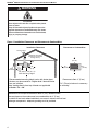
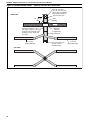
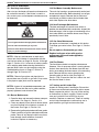
Figure 1: Installation Clearances and Clearances to Combustibles
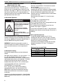
WARNING
Fire Hazard
Some objects will catch fire or explode when placed
close to heater.
Keep all flammable objects, liquids and vapors the
required clearances to combustibles away from heater.
Failure to follow these instructions can result in death,
injury or property damage.
6"**
(15 cm)
31"
(79 cm)
3"
6"
(15 cm)
Clearances to Combustibles
24" for
adequate
air flow access
axial fan.
10'
(3 m)
Wall
Terminal
Roof Terminal
Top
20' (6.0 m) - 30' (9.1 m)
Max. Mounting Height*
Installation Clearances
(Optional separated
combustion concentric
venting shown.)
* Recommended mounting height varies with heater input.
Heaters may be mounted at a higher level if destratification
fans are installed.
Note: Venting directly from top of heater not applicable
on Models 150 - 400.
Clearance to Vent: 2" (5 cm)
**31" (79 cm) minimum is necessary
for servicing.
The heater must always be installed at least 6' (2 m) above the floor.
The vent pipe must have clearance from combustibles by 2" (5 cm).
If installed at low levels where individuals can come in contact with hot heat
exchanger components, adequate guarding must be provided.

SECTION 4: NATIONAL STANDARDS AND APPLICABLE CODES
5
SECTION 4: NATIONAL STANDARDS AND APPLICABLE CODES
4.1 Gas Codes
The type of gas appearing on the name plate
must be the type of gas used. Installation must
comply with national and local codes and
requirements of the local gas company.
United States: Refer to NFPA 54/ANSI Z223.1 -
latest revision, National Fuel Gas Code.
Canada: Refer to CSA B149.1 Natural Gas and
Propane Installation Code.
4.2 Aircraft Hangars
Installation in aircraft hangars must be in
accordance with the following codes:
United States: Refer to Standard for Aircraft
Hangars, NFPA 409 - latest revision.
Canada: Refer to Standard CSA B149.1 Natural
Gas and Propane Installation Code.
• In aircraft storage and servicing areas, heaters
shall be installed at least 10' (3 m) above the
upper surface of wings or of engine enclosures
of the highest aircraft which may be housed in
the hangar. The measurement shall be made
from the wing or engine enclosure (whichever is
higher from the floor) to the bottom of the heater.
• In shops, offices and other sections of aircraft
hangars communicating with aircraft storage or
servicing areas, heaters shall be installed not
less than 8' (2.4 m) above the floor.
• Suspended or elevated heaters shall be so
located in all spaces of aircraft hangars that they
shall not be subject to injury by aircraft, cranes,
movable scaffolding or other objects. Provisions
shall be made to assure accessibility to
suspended heaters for recurrent maintenance
purposes.
4.3 Parking Structures and Repair Garages
Installation in garages must be in accordance
with the following codes:
United States: Standard for Parking Structures
NFPA 88A - latest revision or the Code for Motor
Fuel Dispensing Facilities and Repair Garages,
NFPA 30A - latest revision. Canada: Refer to
CSA B149.1 Natural Gas and Propane
Installation Code.
• In accordance with the Standard for Parking
Structures NFPA 88A, heaters must be located
a minimum of 18" (50 cm) below the floor-ceiling
assembly or 18" (50 cm) above the floor.
• In accordance with the Code for Motor Fuel
Dispensing Facilities and Repair Garages,
NFPA 30A - latest revision, heaters must not be
installed less than 8' (2.4 m) above the floor.
4.4 Electrical
The heater must be electrically grounded in
accordance with the following codes:
United States: Refer to National Electrical
Code
®
, NFPA 70 - latest revision. Wiring must
conform to the most current National Electrical
Code
®
, local ordinances and any special
diagrams furnished.
Canada: Refer to Canadian Electrical Code,
CSA C22.1 Part 1 - latest revision.
4.5 Venting
The venting must be installed in accordance
with the requirements within this manual and
the following codes:
United States: Refer to NFPA 54/ANSI Z223.1 -
latest revision, National Fuel Gas Code.
Canada: Refer to CSA B149.1 Natural Gas and
Propane Installation Code.
4.6 High Altitude
These heaters are approved for installations up
to 2000' (610 m). In USA, consult factory if
heater is to be installed above 2000' (610 m). In
Canada, high altitude conversion kits are
available for installations up to 4500' (1370 m).
Installations above 4500' (1370 m) in Canada is
by local or provincial authority.

COMBAT
®
UHA UNIT HEATER INSTALLATION OPERATION AND SERVICE MANUAL
6
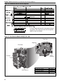
SECTION 5: MAJOR COMPONENTS
5.1 General
Heaters are designed for installation above 6'
(1.8 m). These heaters must be installed within the
heated space. Duct delivery systems are not
permitted with axial fan units. When handling or
supporting the heater from below, ensure that the
weight is taken at the support points.
5.2 Suspension
For typical suspension, See Page 6, Figure 2.
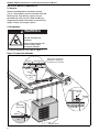
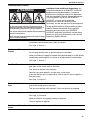
Figure 2: Suspension Methods
WARNING
Crush Hazard
Use 3/8" threaded rod
minimum.
Failure of the supports can
result in death, injury
or property damage.
Cone Point
Set Pin
Window
Clamp
Unistrut
3/8"
Threaded
Rod
Nut
Washer
Riv
Nut
Support Points
Ensure all suspension
hardware is torqued to
a minimum of 20 ft lbs.
Washer
3/8"
Threaded
Rod
Nut
Unistrut
Channel Nut

SECTION 6: VENTING
7
SECTION 6: VENTING
6.1 Venting
This heater must be vented in accordance with the
rules contained in this manual and with the following
national codes and any state, provincial or local
codes which may apply: United States: Refer to
NFPA 54/ANSI Z223.1 - latest revision, National
Fuel Gas Code; Canada: Refer to CSA B149.1
Natural Gas and Propane Installation Code.
Any portion of vent pipe passing through a
combustible wall must have a listed thimble to
conform with the above codes.
The heater may be installed unvented in
certain circumstances according to building
ventilation codes. Refer to the above codes and
Page 8, Section 6.3 for further information.
Unvented operation also requires compliance with
the clearances to combustibles given on Page 4,
Figure 1.
The bottom of the vent or air intake terminal shall not
be located less than 1' (.3 m) above grade level.
The vent shall not terminate less than 7' (2.1 m)
above grade where located adjacent to public
walkways.
Vent terminal must be installed at a height sufficient
to prevent blockage by snow and building materials
protected from degradation by flue gasses.
Vent terminal must be beyond any combustible
overhang.
Secure all joints with corrosion resistant #8 x 3/8"
sheet metal screws.
For single wall venting, pressure sensitive aluminum
tape or silicone sealant must be used to seal all
joints.
Aluminum tape shall have a minimum temperature
rating of 400° F (204° C) and meet SMACNA AFTS-
100-73 standards. High temperature silicone
sealant must have a minimum temperature rating of
480° F (250° C).
6.1.1 United States Requirements
Vent must terminate at least 3' (.9 m) above any
forced air inlet located within 10' (3.1 m).
Vent must terminate at least 4' (1.2 m) below,
4' (1.2 m) horizontally from, or 1' (.3 m) above any
door, operable window, or gravity air inlet into any
building.
NFPA 54/ANSI Z223.1 - latest revision, National
Fuel Gas Code specifies a 4' (1.2 m) horizontal vent
terminal clearance from gas and electric meters,
regulators and relief equipment.
6.1.2 Canadian Requirements
The vent shall not terminate within 6' (1.8 m) of a
mechanical air supply inlet to any building.
The vent shall not terminate within 3' (.9 m) of a
window or door that can be opened in any building,
any non-mechanical air supply inlet to any building,
or of the combustion air inlet of any other appliance.
6.2 Vent Installation
For vented units, the vent must terminate outside of
the building.
Vents must be fully sealed and correctly sized for
the model. If the vent passes through a wall or
ceiling of combustible material, it must be enclosed
by a listed thimble and be separated from the
thimble by at least a 2" (5 cm) air gap.
For separated combustion models, vents and air
intakes must be a fully sealed system and correctly
sized for the model. Vent should be assembled as
detailed on Page 9, Figure 3 through Page 12,
Figure 8. The joints between the vent terminal and
the roof or wall must be properly sealed. If the vent
passes through a wall or ceiling of combustible
material, it must be enclosed by a listed thimble and
be separated from the thimble by at least a 2" (5 cm)
air gap.
Vents and air intakes must be adequately
supported so that the heater does not bear the
weight of the pipes.
For vent termination See Page 9, Figure 3 through
Page 12, Figure 8.
6.2.1 Standard Vented Heaters
(Models UHA 150 - 400)
The vent must be fitted with a low resistance
terminal. See Page 9, Figure 3 through Page 9,
Figure 4. Standard vented heaters do not allow
outdoor air intake for combustion air.
WARNING
Fire Hazard
Some objects will catch fire or explode when placed
close to heater.
Keep all flammable objects, liquids and vapors the
required clearances to combustibles away from heater.
Failure to follow these instructions can result in death,
injury or property damage.

COMBAT
®
UHA UNIT HEATER INSTALLATION OPERATION AND SERVICE MANUAL
8
6.2.2 Separated Combustion Heaters
(Models UHAS 150 - 400)
The heaters are designed to be installed as
separated combustion heaters. The vent and air
intake are run as separate pipes to the wall or roof
terminals. See Page 12, Figure 8. As an option, the
vent and air intake are run as separate pipes to a
concentric vent box and a concentric vent/air intake
pipe penetrates the wall or roof.
6.3 Unvented Operation
For unvented operation in commercial installations,
sufficient ventilation must be provided in the amount
of 4 cfm per 1000 Btu/h firing rate (United States); 3
cfm per 1000 Btu/h firing rate (Canada).
WA R NI N G: Combustion by-products contain a
chemical known to the State of California to cause
cancer and birth defects or other reproductive
harm.
6.4 Horizontal Venting
Horizontally vented heaters must be individually
vented.
Vent pipe must be sloped ¼" (.6 cm) for every 1' (.3
m). For vent lengths greater than 5' (1.5 m),
condensation will form. Insulation is recommended
and condensation drains may be desired. For vents
pitched up toward the vent terminal, place the
condensation drain within 5' (1.5 m) of the heater.
In noncombustible walls only, vent terminal
(P/N 02537801-1P) may be used.
For 4'' (10 cm) vents in either combustible or
noncombustible walls, use vent terminal (P/N
90502100) or equivalent insulated vent terminal.
Follow the manufacturer's instructions for proper
installation.
Instead of an insulated vent terminal, a listed thimble
(with 2" air gap) may be used with a 4" vent cap (P/N
90502102).
6.5 Vertical Venting
Vertically vented heaters can be common vented
(up to 4 heaters).
For vent lengths greater than 5' (1.5 m),
condensation will form. Insulation is recommended
and condensation drains may be desired. Vent from
the rear of the heater cabinet then run the vent
vertically and use a condensate drain at the bottom
of the vertical vent.
Vent pipe must be sloped 1/4'' (.6 cm) for every
1' (.3 m).
For 4'' (10 cm), an approved vent cap
(P/N 90502102) must be used.
For 6'' (15 cm) common vent, an approved vent cap
(P/N 90502103) must be used.
For common vertical venting of more than two
heaters, See Page 10, Figure 5.
A vent shall not extend less than 2' (.6m) above the
highest point where it passes through a flat roof of a
building.
6.6 Length Requirements
If using vent lengths greater than 5' (1.5 m),
condensation will form in the vent pipe. Insulation
and additional sealing measures (high temperature
silicone at all seams) are required.
The entire vent should be insulated with foil faced
fiberglass insulation (1/2" thick, 1-1/2# density
minimum).
Maximum Vent Lengths Table
Carbon Monoxide Hazard
Heaters installed unvented must
be interlocked with sufficient
building exhaust.
Heaters must be installed
according to the installation
manual.
Failure to follow these
instructions can result in death
or injury.
WARNING
Model UHA[S]
150 - 400
# of Elbows
40 ft (12.2 m) 1
35 ft (10.7 m) 2
30 ft (9.1 m) 3
25 ft (7.6 m) 4
20 ft (6.1 m) 5

SECTION 6: VENTING
9
6.7 Vent Material
Vent material may be single wall 26 ga. (minimum)
galvanized steel or equal thickness stainless steel.
Completely seal all joints, refer to Page 7, Section
6.2.
If penetrating a combustible wall or roof, a listed
thimble with 2" (5 cm) clearance must be used.
Where local codes permit, a single section of type
B-1 vent material may be used at the roof or wall
penetration instead of a thimble. Ensure vent
manufacturer's clearance from vent material is
maintained. Seal annular space of the type B-1 vent
as well as all joints in the remaining vent.
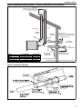
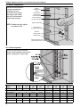
Figure 3: Vent and Roof Detail
Figure 4: Standard Vented Heater - Vertical and Horizontal Vent Termination
Roof
Vent
Terminal
Listed Thimble
Flashing
or Rain Collar
Vent
2" Air Gap to
Combustible Material
Vent
Terminal
4" Dia.Vent
Flashing
(By Others)
Listed
Thimble
(2" Clearance)
Vent Terminal
Vertical
Option
Horizontal
Option
Vent
Listed
Thimble
(2" Clearance)
Flashing
(By Others)
12" (31 cm)
Minimum
Condensate
Trap to Drain
(Optional)
Note: Vent supports
not shown.
90°
Bend
Model Vent Diameter Part Number
UHA 150 - 400 4" (10 cm) 90502102

COMBAT
®
UHA UNIT HEATER INSTALLATION OPERATION AND SERVICE MANUAL
10
Figure 5: Standard Vented Heater - Common Vertical Vent Termination
Roof
18" (46 cm)
Min.
Type "B" vent cap
(7" or 8") may be used.
(These are not available
from Roberts-Gordon.)
Roof
Flashing
Approved
Thimble
(If Applicable)
Type "B" Vent Pipe
4" (10 cm)
Single Wall Pipe
4" (10 cm)
Single Wall Pipe
"D" Area must equal sum
of open area of
individual vents.
"D"
Single Wall Pipe
The last section of vent pipe
passing through the roof or
wall may be Type "B" vent pipe.
All other vent materials in the
building must be single wall
vent pipe.
TOP VIEW
SIDE VIEW

SECTION 6: VENTING
11
Figure 6: Separated Combustion Heater - Vertical and Horizontal Vent Termination
Figure 7: Concentric Vent Box
Vent
Termination
Listed Thimble through
Combustible Wall
Vent
12" (31 cm)
Minimum from wall
to vent termination.
Air Intake
Condensate
Trap to Drain
(Optional)
12" (31 cm)
Minimum from air inlet to vent
termination (may be horizontal
or vertical clearance).
Air Intake
Termination
Note: Vent supports not shown
Vent
Air Intake*
12" (31 cm)
Minimum from air inlet to vent
termination (may be horizontal
or vertical clearance).
Vertical
Option
Horizontal
Option
90°
Bend
Model Vent Diameter Terminal P/N
UHAS 150 - 400 4" (10 cm) 90502102
Model *Air Intake Diameter Terminal P/N
UHAS 150 - 250 4" (10 cm) 90502102
UHAS 300 - 400 5" (13 cm) 90502105

COMBAT
®
UHA UNIT HEATER INSTALLATION OPERATION AND SERVICE MANUAL
12
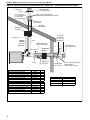
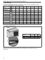
Figure 8: Concentric Vertical and Horizontal Vent Termination - Separated Combustion Heater
Vent
Air Intake*
Concentric
Vent Box
Vertical
Option
10' (3 m)
Maximum
Horizontal
Option
Concentric
Vent Box
Vent
Combustion
Air Terminal
Vent Terminal
with Baffle Plate
Flashing
(By Others)
Condensate Trap
to Drain (Optional)
4" Type B-1
Vent
Storm Collar (By Others)
(Attach with 3 sheet metal screws.)
UHA 150-250:
6" Dia. Single Wall
UHA 300-400:
8" Dia. Single Wall
Air Intake*
6" (16 cm)
Minimum
12" (31 cm)
Maximum
Combustion
Air Terminal
Vent Terminal
with Baffle Plate
4"
Type
B-1
Vent
Storm Collar (By Others)
(Attach with 3
sheet metal screws.)
Description Part Number Qty.
Concentric Vent Kit (150 - 250) UHVK1
Concentric Vent Box Top & Side Assembly 90504113 1
Concentric Vent Box Bottom Assembly 90504112 1
Screw #6 x 3/8 Self Drilling 91119100 14
4" Vent Terminal with Baffle Plate 90502102R 1
6" Combustion Air Terminal 90502103 1
Description Part Number Qty.
Concentric Vent Kit (300 - 400) UHVK2
Concentric Vent Box Top & Side Assembly 90504013 1
Concentric Vent Box Bottom Assembly 90504012 1
Screw #6 x 3/8 Self Drilling 91119100 14
4" Vent Terminal with Baffle Plate 90502102R 1
8" Combustion Air Terminal 90502104 1
Model Vent Diameter
UHAS 150 - 400 4" (10 cm)
Model *Air Intake Diameter
UHAS 150 - 250 4" (10 cm)
UHAS 300 - 400 5" (13 cm)

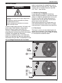
SECTION 7: AIR SUPPLY
13
SECTION 7: AIR SUPPLY
7.1 Separated Combustion Installation
When installed as a separated combustion heater
(UHAS), the air for combustion is drawn in from
outside the building. It is important to ensure that
there is adequate space around heater to provide air
for the axial air distribution fan.
7.2 Unvented Installation
It is important to ensure that there is adequate fresh
air supply at all times for both combustion and
heating requirements in accordance with local and
national codes.
WARNING: Combustion by-products contain a
chemical known to the State of California to cause
cancer and birth defects or other reproductive
harm.
7.3 Building Ventilation
Where ventilation is required, air must be taken from
an outside point where it is not likely to be
contaminated or obstructed.
7.4 Outside Combustion Air Supply
If outside combustion air supply is required,
separated combustion model (UHAS) heaters must
be used.
IMPORTANT: If the building has a slight negative
pressure or corrosive contaminants such as
halogenated hydrocarbons are present in the air, an
outside combustion air supply to the heater is
required. Seal all combustion air pipe joints.
The air supply duct may have to be insulated to
prevent condensation on the outer surface. The
outside air terminal must not be more than 1' (31
cm) above the vent terminal.
7.4.1 Length Requirements
Follow the constraints listed on Page 8, Section 6.6.

COMBAT
®
UHA UNIT HEATER INSTALLATION OPERATION AND SERVICE MANUAL
14
SECTION 8: GAS PIPING
It is important that the gas supply pipe and the
electrical connections do not support any of the
heater’s weight.
A gas meter is connected to the service pipe by the
gas supply company. An existing meter should be
checked, preferably by the company, to ensure that
the meter is adequate for the rate of gas supply
required.
Installation pipes must be fitted in accordance with
local and national codes. Pipes of smaller size than
the heater inlet gas connection should not be used.
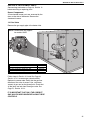
8.1 Connections
Connect the heater to the gas supply ensuring that
the final connections are as follows:
• Gas supply pipe work is run in medium or heavy
gauge tubing in compliance with local and
national codes.
• Meter and service must be large enough to
handle all the burners being installed plus any
other connected load. The gas pipe which feeds
the system must be large enough to supply the
required gas with a maximum pressure drop of
1/2" w.c. When gas piping is not included in the
layout drawing, contact the local gas supplier.
• An isolating valve and union connection should
be used and fitted into the supply adjacent to the
heater.
• A minimum 1/8" NPT plugged tapping
accessible for test connection must be installed
immediately upstream of the gas supply
connection to the heater.
• For suspended heaters, an approved metal
flexible connection between the isolating valve
and the heater may be used. To reduce
pressure loss, use one pipe size larger than
the heater gas connection.
IMPORTANT - The complete installation must be
purged and tested for gas soundness in accordance
with local and national codes.
• Do not high pressure (in excess of 1/2 psi
[14" w.c.]) test the gas piping with the burner
connected. Close manual shut-off valve
during any pressure testing equal to or less
than 1/2 psi (14" w.c.). Failure to follow these
instructions can result in property damage.
Check the pipe and tubing ends for leaks before
placing heating equipment into service. When
checking for gas leaks, use a soap and water
solution; never use an open flame.
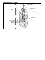
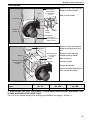
Figure 9: Gas Connection
WARNING
Fire Hazard
Connect gas supply according to Figure 9.
Gas can leak if not installed properly.
Failure to follow these instructions can result in death,
injury or property damage.
Fire Hazard
Connect gas supply according to Figure 9.
Gas can leak if not installed properly.
Failure to follow these instructions can result in death,
injury or porperty damage.
Gas Shut-off Valve
Drip Leg
Cap
Union
Connection
Option B:
Medium or Heavy
Gauge Pipe
Gas Connector
Option A:
Stainless Steel
Flex Gas
Connector
Do not bend flexible
gas connector
sharply.
• Hold gas nipple
securely with pipe
wrench when
attaching the flex gas
connector.
• Do not twist flexible
gas connector.
• Ensure all
joints are
gas tight.
Page is loading ...
Page is loading ...
Page is loading ...
Page is loading ...
Page is loading ...
Page is loading ...
Page is loading ...
Page is loading ...
Page is loading ...
Page is loading ...
Page is loading ...
Page is loading ...
Page is loading ...
Page is loading ...
Page is loading ...
Page is loading ...
Page is loading ...
Page is loading ...
Page is loading ...
Page is loading ...
Page is loading ...
Page is loading ...
Page is loading ...
Page is loading ...
Page is loading ...
Page is loading ...
Page is loading ...
Page is loading ...
Page is loading ...
Page is loading ...
Page is loading ...
Page is loading ...
-
 1
1
-
 2
2
-
 3
3
-
 4
4
-
 5
5
-
 6
6
-
 7
7
-
 8
8
-
 9
9
-
 10
10
-
 11
11
-
 12
12
-
 13
13
-
 14
14
-
 15
15
-
 16
16
-
 17
17
-
 18
18
-
 19
19
-
 20
20
-
 21
21
-
 22
22
-
 23
23
-
 24
24
-
 25
25
-
 26
26
-
 27
27
-
 28
28
-
 29
29
-
 30
30
-
 31
31
-
 32
32
-
 33
33
-
 34
34
-
 35
35
-
 36
36
-
 37
37
-
 38
38
-
 39
39
-
 40
40
-
 41
41
-
 42
42
-
 43
43
-
 44
44
-
 45
45
-
 46
46
-
 47
47
-
 48
48
-
 49
49
-
 50
50
-
 51
51
-
 52
52


Roberts Gorden 350 User manual
- Category
- Water heaters & boilers
- Type
- User manual
Ask a question and I''ll find the answer in the document
Finding information in a document is now easier with AI
Related papers
-
Roberts Gorden 250 User manual
-
-
-
-
-
-
-
-
Radiant BH-80 User manual
-
Other documents
-
Modine Separated Combustion Gas-Fired Unit Heaters Heaters Installation & Service Manual
-
Modine HDS Series Heaters Installation & Service Manual
-
Modine PDP User manual
-
-
Modine PDP400 User manual
-
 Duke Manufacturing Panel Rework Instruction User manual
-
Roberts Gordon COMPACT DF SF Installation guide
-
Rheem Professional Classic Series: Direct Vent (Vertical Option) User manual
-
Modine HD60A Operating instructions
-
