NON-CE
&
Frymaster/Dean, a member of the Commercial Food Equipment Service Association,
recommends using CFESA Certified Technicians.
24-Hour Service Hotline 1-800-551-8633 JUNE 2004
PRINTED IN THE USA
*8196031*
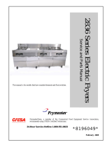
24G Series Flatbottom
Gas Fryers
Service & Parts Manual
Models 1824G, 2424G and 1824/2424G
Systems with Built-In Filtration

Please read all sections of this manual and retain for future reference.
This product has been certified as commercial cooking equipment and MUST be installed by
professional personnel as specified. Installation, maintenance and repairs should be performed
by your FRYMASTER/DEAN FACTORY AUTHORIZED SERVICE CENTER.
DANGER
Do not store or use gasoline or other flammable vapors and liquids in the vicinity of this or any
other cooking appliance.
DANGER
Instructions explaining procedures to be followed MUST be posted in a prominent location in
the event the operator detects a gas leak. This information can be obtained from the local gas
company or gas supplier.
WARNING
Improper installation, adjustment, alteration, service or maintenance can cause property
damage, injury or death. Read the installation, operating and maintenance instructions
thoroughly before installing or servicing this equipment.
DANGER
Safe and satisfactory operation of your equipment depends on proper installation. Installation
MUST conform with local codes, or in absence of local codes, with the National Fuel Gas Code,
ANSI Z223.1; The Natural Gas Installation Code, CAN/CGA-B149.1; The Propane Installation
Code, CAN/CGA-B149.2; or The latest edition of the National Electric Code, N.F.P.A. 70.
NOTICE
IF, DURING THE WARRANTY PERIOD, THE CUSTOMER USES A PART FOR THIS ENODIS
EQUIPMENT OTHER THAN AN UNMODIFIED NEW OR RECYCLED PART PURCHASED
DIRECTLY FROM FRYMASTER/DEAN, OR ANY OF ITS AUTHORIZED SERVICE CENTERS,
AND/OR THE PART BEING USED IS MODIFIED FROM ITS ORIGINAL CONFIGURATION, THIS
WARRANTY WILL BE VOID. FURTHER, FRYMASTER/DEAN AND ITS AFFILIATES WILL NOT BE
LIABLE FOR ANY CLAIMS, DAMAGES OR EXPENSES INCURRED BY THE CUSTOMER WHICH
ARISE DIRECTLY OR INDIRECTLY, IN WHOLE OR IN PART, DUE TO THE INSTALLATION OF
ANY MODIFIED PART AND/OR PART RECEIVED FROM AN UNAUTHORIZED SERVICE CENTER.
DANGER
The crumb tray in fryers equipped with a filter system must be emptied into a fireproof container
at the end of frying operations each day. Some food particles can spontaneously combust if left
soaking in certain shortening material. Additional information can be obtained in the filtration
manual included with the system.

DANGER
The front ledge of the fryer is not a step. Do not stand on the fryer. Serious injury can result
from slips or contact with the hot oil.
WARNING
Drawings and photos used in this manual are intended to illustrate operational, cleaning and
technical procedures and may not conform to on-site management operational procedures.
WARNING
No structural material on the fryer should be altered or removed to accommodate placement of
the fryer under a hood. Questions? Call the Frymaster/Dean Service Hotline at 1-800-551-8633.
This equipment is to be installed in compliance with the basic plumbing code of The Building
Officials and Code Administrators International, Inc. (BOCA) and the Food Service Sanitation
Manual of the Food and Drug Administration.
COMPUTERS (WHERE APPLICABLE)
FCC
This device complies with Part 15 of the FCC rules. Operation is subject to the following two conditions:
1) This device may not cause harmful interference, and 2) This device must accept any interference
received, including interference that may cause undesired operation. While this device is a verified Class
A device, it has been shown to meet the Class B limits.
CANADA
This digital apparatus does not exceed the Class A or B limits for radio noise emissions as set out by the
ICES-003 standard of the Canadian Department of Communications.
Cet appareil numerique n’emet pas de bruits radioelectriques depassany les limites de classe A et B
prescrites dans la norme NMB-003 edictee par le Ministre des Communcations du Canada.
DANGER
THIS PRODUCT CONTAINS CHEMICALS KNOWN TO THE STATE OF CALIFORNIA TO CAUSE
CANCER AND/OR BIRTH DEFECTS OR OTHER REPRODUCTIVE HARM.
Operation, installation, and servicing of this product could expose you to airborne particles of
glasswool or ceramic fibers, crystalline silica, and/or carbon monoxide. Inhalation of airborne
particles of glasswool or ceramic fibers is known to the State of California to cause cancer.
Inhalation of carbon monoxide is known to the State of California to cause birth defects or other
reproductive harm.
WARNING
Do not bang fry baskets or other utensils on the fryer’s joiner strip. The strip is present to seal
the joint between the fry vessels. Banging fry baskets on the strip to dislodge shortening will
distort the strip, adversely affecting its fit. It is designed for a tight fit and should only be
removed for cleaning.

24G Series Flatbottom Gas Fryers
Service & Parts Manual
TABLE OF CONTENTS
PAGE #
1.
1.1
1.2
1.3
1.4
1.5
1.6
1.7
1.7.1
1.7.2
1.7.3
1.7.4
1.7.5
1.7.6
1.8
1.8.1
1.8.2
1.8.3
1.8.4
1.8.5
1.9
1.9.1
1.9.2
1.9.3
1.10
1.10.1
1.10.2
1.10.3
1.10.4
1.10.5
SERVICE PROCEDURES
Functional Description
Accessing Fryers for Servicing
Cleaning Gas Valve Vent Tube
Adjusting Burner Manifold Gas Pressure
Adjusting Pilot Flame
Calibrating the Thermatron Temperature Controller
Replacing Fryer Components
Remove/Replace Temperature Probe or High-Limit Thermostat
Removing /Replacing Rocker Switches
Replacing the Gas Valve
Replacing the Pilot Assembly or Direct Spark Ignitor
Removing/Replacing Blower Assembly or Air Prover Switch
Replacing the Frypot
Troubleshooting and Problem Isolation
Ignition Failures
Improper Burner Functioning
Improper Temperature Control
Filtration Problems
Leakage
Troubleshooting Guides
Pilot Burner Malfunctions
Main Burner Malfunctions
Indicator Lights
Wiring Diagrams
24G Series Single Fryers, Non-CE
24GTI with Drain Safety Switch, and Boil Out Option Enabled
24GTI with Drain Safety Switch, and Boil Out Option Disabled
24G Series Single Fryers, CE Approved
24GTI Oil Return/Filter System
1–1
1–1
1–5
1–6
1–6
1–7
1–7
1–9
1–9
1–11
1–12
1–12
1–13
1–15
1–19
1–20
1–21
1–23
1–23
1–25
1–26
1–26
1–27
1–28
1–29
1–29
1–30
1–31
1–32
1–33

24G Series Flatbottom Gas Fryers
Service & Parts Manual
TABLE OF CONTENTS (cont.)
PAGE #
2.
2.1
2.2
2.3
2.3.1
2.3.2
2.3.3
2.4
2.5
2.5.1
2.5.2
2.6
2.7
PARTS LIST
Blower Assembly, Combustion Air
Burner Manifold and Related Components
Cabinetr
y
Backs, Bases, Casters, Sides, Etc.
Door Assemblies and Component Parts
Flue Caps, Top Caps, and Related Components
Control Panels, Wireways, and Related Components
Filtration
Under Fryer Filter (UFF) Components
ND90 Built-In Filter System Components
Frypot, Drain and Oil-Return Components
Wiring Connectors, Pin Terminals and Power Cords
2–1
2–1
2–2
2–4
2-4
2-6
2-8
2–10
2–12
2–12
2–15
2–18
2–20

24G SERIES FLATBOTTOM GAS FRYERS
CHAPTER 1: SERVICE PROCEDURES
1-1
1.1 Functional Description
24G Series Flatbottom gas fryers contain a welded steel frypot (mild steel) with heat-transfer ducting
on the frypot bottom for efficient heating of oil without scorching. A draft inducer draws air over
the burners for combustion. Air movement directs the combustion products back and forth across
the frypot bottom by means of a set of baffles, transferring the heat evenly. Cold air is prevented
from entering the combustion chamber and cooling the oil during the coasting cycle.
Flames originate from orifices in three tubular burners positioned at the front and beneath the frypot.
The diameter of the orifices differs for Natural (CE:G20/G25) and LP (CE:G31) gas as indicated in
the table below.
NON-CE (Altitudes of 2000 feet or less)
EQUIPMENT
PRESSURE
MODEL
INPUT
(BTU)
GAS TYPE
ORIFICE
[DRILL SIZE (MM)]
ORIFICE
PART #
QTY
MBAR INCH W.C.
1824/2424G 120
NAT
LP
#34 (2.82)
#50 (1.78)
810-2051
810-2317
3
3
10
27.5
4
11
CE ONLY (Altitudes of 2000 feet or less)
EQUIPMENT
PRESSURE
MODEL
INPUT
(kW)
GAS TYPE
ORIFICE
(MM)
ORIFICE
PART #
QTY
MBAR INCH W.C.
1824/2424G
30,0
(88,000
BTU)
G20
G25
G31
2,50
2,50
1,60
810-2628
810-2628
810-2317
3
3
3
14,5
21,0
31,0
5,8
8,4
12,44

24G SERIES FLATBOTTOM GAS FRYERS
CHAPTER 1: SERVICE PROCEDURES
1-2
An electromechanical gas valve regulates gas flow to the manifold. 24G Series Flatbottom gas
fryers are equipped with either a 120-volt valve system (standing pilot) or a 24-volt valve system
(electronic ignition or CE standing pilot). Units may be configured with either a pilot ignition system
(standing pilot) or an electronic ignition system (direct spark ignition).
Pilot System Configuration
The pilot system is comprised of the pilot orifice, pilot hood, and a thermocouple. The pilot serves
two purposes. The first is to light the burner, the second is to heat the thermocouple. In operation,
the thermocouple is in contact with the pilot flame and generates millivolts. The millivolt output
energizes the gas valve pilot coil, which in turn opens the pilot valve. If the pilot flame is
extinguished, voltage is lost to the gas valve pilot coil and the pilot valve closes. The gas valve is
constructed so that the main valve will not open if the pilot valve is not open. The pilot flame must
be manually lit when the fryer is first placed into operation. A separate circuit, activated by the fryer
ON/OFF switch, provides voltage through the Thermatron temperature controller to the gas valve
main coil, which opens the main valve.
Thermatron Temperature
Controller
High-Limit
Thermostat
Line Voltage
Line Voltage
The Pilot System
120V
MELT CYCLE DISABLE
6
5
1
AC1
3
AC2 3A 2A
7
8
9
1A
EXT POT
PROBE
10
11
2
COM
RELAY
NO
12 13
NC
14
Thermocouple
Pilot Coil
Main Coil
Gas
Valve
Pilot
ON/
OFF
Switch
Electronic Ignition Configuration
In units configured for electronic ignition, an ignition module connected to an ignitor assembly
replaces the pilot system. The ignition module performs three important functions: it provides an
ignition spark, supplies voltage to the gas valve, and proofs the burner flame.
The module contains a time delay circuit and a coil that activates the gas valve. The ignitor
assembly consists of a spark plug and a flame sensor element.
At start-up the ON/OFF switch is placed in the "ON" position, supplying 115 VAC or 230 VAC,
according to system configuration, to the Thermatron interface board. The voltage is stepped down

24G SERIES FLATBOTTOM GAS FRYERS
CHAPTER 1: SERVICE PROCEDURES
1-3
via transformer to 24 VAC before entering the ignition module. If resistance in the temperature
probe indicates the temperature in the frypot is below 150°F (66°C), the current flows through a melt
cycle circuit where a switch alternately closes for approximately 4 seconds and opens for
approximately 20 seconds. If the temperature is 150°F (66°C) or above, the current flows through a
heat circuit, bypassing the timer switch. In either case, current is supplied to the other leg of the heat
relay coil, which then closes an electronic switch in the 24 VAC circuit to provide current to the
ignition module.
Circuitry in the ignition module sends 24 VAC current to the gas valve via a normally closed high-
limit switch and a drain safety switch. Simultaneously, the module causes the ignitor to spark for up
to 11 seconds to light the burner flame. A flame sensor verifies that the burner is lit by measuring
the flow of microamps through the flame. If the burner does not light (or is extinguished), current to
the ignition module is interrupted, preventing the main valve from opening, and the ignition module
"locks out" until the power switch is turned "OFF", then back "ON".
A temperature probe monitors the temperature in the frypot. When the programmed setpoint
temperature is reached, resistance in the probe causes the heat cycle circuitry in the controller to
interrupt current flow through the heat relay. This in turn interrupts the 24 VAC to the ignition
module, resulting in closure of the gas valve.
Control Options
24G Series Flatbottom gas fryers are equipped with Thermatron temperature controller. The fryer is
turned on and off by means of a rocker switch and the temperature is set by adjusting a
potentiometer. An interface board is located in the wireway box behind the control panel, or in a
component box inside the cabinet (depending on fryer configuration).
The Thermatron temperature controller operates by comparing resistance between the potentiometer
setting and the temperature probe. If the resistance values don’t match, an on-board relay energizes,
sending voltage to the gas valve, which supplies fuel to the burners. When the resistance values are
equal, the on-board relay de-energizes, interrupting voltage to the gas valve, which stops the fuel
flow.
Depending on the system configuration and destination, 24VAC, 115VAC or 208/230VAC
controller boards are used.

24G SERIES FLATBOTTOM GAS FRYERS
CHAPTER 1: SERVICE PROCEDURES
1-4
MELT CYCLE DISABLE
6
5
1
AC1
3
AC2 3A 2A
7
8
9
1A
EXT POT
PROBE
10
11
2
COM
RELAY
NO
12
13
NC
14
Not used
Line voltage enters the interface board at terminals 1 and 3. The temperature controls
(potentiometer) are connected to terminals 7, 8 and 9. The sensor probe circuit is connected to
terminals 10 and 11. The high-limit and gas valve routes through terminal 12. Terminals 2 and 13
are jumped out. Terminals 5 and 6 are the melt-cycle disable circuit. The melt cycle is enabled
unless terminals 5 and 6 are jumped out.
Thermatron Controller Board

24G SERIES FLATBOTTOM GAS FRYERS
CHAPTER 1: SERVICE PROCEDURES
1-5
Safety Components
All 24G Series Flatbottom gas fryers are equipped with a high-limit thermostat. In the event that the
fryer fails to properly control the oil temperature, the high-limit thermostat prevents the fryer from
overheating to flash point. The high-limit thermostat acts as a normally closed power switch that
opens when exposed to temperatures above 410°F [(210°C)- CE] to 435°F [(224°C)- Non-CE]. CE
and non-CE high-limits are not interchangeable.
Frying systems with built-in filtration are equipped with drain microswitches that disable the fryer if
the drain valves are not completely closed. Opening a drain valve (i.e. filtering or draining the fryer)
automatically opens the reset switch circuit. The drain valve must be fully closed prior to resetting
the safety switch.
1.2 Accessing Fryers for Servicing
DANGER
Moving a fryer filled with cooking oil/shortening may cause spilling or splattering of
the hot liquid. Follow the draining instructions included with the fryer before
attempting to relocate a fryer for servicing.
NOTE: Perform the following only if the fryer cannot be serviced in its installed location. Some of
the following service procedures require the fryer to be connected to the gas and/or electrical supply.
1. Shut off the gas supply to the unit. Unplug the power cords. Remove any attached restraining
devices.
2. Disconnect the unit from the gas supply.
3. Relocate the fryer for service accessibility.
4. After servicing is complete, reconnect the unit to the gas supply, reattach restraining devices, and
plug in the electrical cords.

24G SERIES FLATBOTTOM GAS FRYERS
CHAPTER 1: SERVICE PROCEDURES
1-6
1.3 Cleaning the Gas Valve Vent Tube (if applicable)
1. Set the fryer power switch and the gas valve to the "OFF" position.
2. Carefully unscrew the vent tube from the gas valve. NOTE: The vent tube may be straightened
for ease in removal.
3. Pass a piece of ordinary binding wire (.052 inch diameter) through the tube to remove any
obstruction. Remove the wire and blow through the tube to ensure it is clear.
4. Reinstall tube and bend so that the opening is pointing downward.
1.4 Adjusting Burner Manifold Gas Pressure
WARNING
This task should be performed by qualified service personnel only.
1. Ensure that the gas valve knob is in the
"OFF" position.
2. Remove the pressure tap plug from the
burner manifold.
3. Insert the fitting for a gas pressure-
measuring device into the pressure tap
hole.
4. Place the gas valve in the "ON" position then place the fryer power switch in the "ON" position.
When the burner lights and continues to burn, note gas pressure reading for correct pressure in
accordance with the table on page 1-1.
Remove pressure tap from burner manifold to
check burner manifold pressure.

24G SERIES FLATBOTTOM GAS FRYERS
CHAPTER 1: SERVICE PROCEDURES
1-7
5. To adjust burner gas pressure, remove the cap from the gas valve regulator and adjust to correct
pressure (arrows).
6. Place the fryer power switch and the gas valve in the "OFF" position. Remove the pressure-
measuring device fitting from the pressure tap hole and reinstall the pressure tap plug.
1.5 Adjusting the Pilot Flame (where applicable)
1. Remove the cap from the pilot adjustment screw hole on the gas valve.
2. Using a small, flat-tipped screwdriver, turn the pilot adjusting screw counterclockwise to
increase length of flame or clockwise to decrease length of flame. Adjust to obtain a flame from
1 to 1-½ inches long.
3. Reinstall the pilot adjustment screw cap.
1.6 Calibrating the Thermatron Temperature Controller
1. Fill the frypot to the proper oil-level line with cooking oil/shortening. If solid shortening is used,
ensure that the shortening is properly packed and melted in the frypot before proceeding.
2. Ensure the fryer ON/OFF switch is in the "OFF" position, and then light the pilot.
3. Place the fryer ON/OFF switch in the "ON" position. Set the Thermatron dial to 325°F (162°C).
4. Allow the oil/shortening to equilibrate at setpoint temperature. This is evident when the burners
have cycled on and off several times.
Non-CE Electronic Ignition
Valve
Pilot Ignition Valve (Line
Voltage)
CE Pilot Ignition Valve

24G SERIES FLATBOTTOM GAS FRYERS
CHAPTER 1: SERVICE PROCEDURES
1-8
5. Insert a good grade thermometer or pyrometer into the frypot within 3 inches of the probe bulb.
Ensure the tip of the thermometer/pyrometer does not touch the bottom or sides of the frypot.
6. If the temperature on the thermometer is higher or lower than 325°F (162°C), the dial is out of
calibration.
7. Calibrate the dial by first loosening two
setscrews in the dial (arrows). After
loosening both setscrews, slowly turn the
dial to match the temperature reading of
the thermometer. Tighten each setscrew,
ensuring the dial does not move on the
shaft during tightening.
8. Allow burners to cycle on and off several
times, then recheck oil temperature as
described in step #5. If the Thermatron
dial temperature matches the thermometer
temperature, the controller is calibrated.
If not, repeat step #7.
9. After calibration is complete, place the
fryer power switch in the "OFF" position
and disconnect the fryer from the
electrical supply.
Loosen two setscrews in dial (arrows) to recalibrate
controller.

24G SERIES FLATBOTTOM GAS FRYERS
CHAPTER 1: SERVICE PROCEDURES
1-9
1.7 Replacing Fryer Components
1.7.1 Remove/Replace Temperature Probe or High-Limit Thermostat
1. Disconnect the fryer from the electrical supply.
2. Allow the frypot to cool for 10 minutes before draining. Drain cooking oil/shortening from the
frypot. Allow the frypot to cool completely before proceeding.
3. Remove the fryer door(s) for access to control panel screws. Lift door up, disengage rod from
lower door bracket, and then remove door. (Current production models have spring-loaded door
pins. Disengage bottom pin from the hinge, and then remove door.)
4. Remove the marine edge (where applicable) from the topcap.
5. Support the control panel and remove
screws securing the panel to the wireway
box. Remove the control panel.
6. On units with switches/indicator lights on
the control panel, mark and unplug the
wiring, and then remove the control panel.
7. Remove screw securing probe/high-limit
access cover to wireway box. Remove
access cover and set aside.
Note: Some systems have a wiring terminal
block mounted on the access cover. Mark
and disconnect the wiring to the terminal
block before removing access cover.

24G SERIES FLATBOTTOM GAS FRYERS
CHAPTER 1: SERVICE PROCEDURES
1-10
8. Remove the sensor bulb guard to access the
probe and high-limit. Current production
systems have a sensor bulb clamp that must
be removed prior to removing the probe or
high-limit from the frypot.
9. On the sensor bulb being removed, loosen
and unscrew completely the compression
nut, then the pass-through nut from the
frypot. Carefully remove the sensor bulb
from the frypot, being careful not to damage
the remaining sensor bulb.
10. If removing high-limit, remove screws
securing high-limit thermostat to wireway
box. Mark and remove wiring from high-
limit housing.
11. If removing the high-limit, remove the
screws securing it to the wireway box.
Mark and remove the wiring from the high-
limit housing.
12. Reverse steps to install new temperature probe or high-limit. If reinstalling high-limit, ensure the
capillary tube is properly routed around the temperature probe before tightening (see photo, Step
#8). Reconnect wiring removed from defective high-limit.
Temperature probe. High-limit.

24G SERIES FLATBOTTOM GAS FRYERS
CHAPTER 1: SERVICE PROCEDURES
1-11
IMPORTANT (High-Limit): When installing new high-limit, ensure the capillary tube and
bulb are positioned properly with the mounting hardware installed prior to tightening the
compression nut. Once tightened, the capillary tube cannot be repositioned.
IMPORTANT (Temperature Probe):
When installing new temperature probe,
ensure probe is positioned properly with the
mounting hardware installed (current
production systems), or 1/8" from frypot
bottom (older systems), prior to tightening
the compression nut. Once tightened, the
probe cannot be repositioned.
1.7.2 Removing/Replacing Rocker Switches
1. Disconnect the fryer from the electrical supply.
2. If switches are located on front panel, remove the screws securing panel to fryer. Do not allow
the panel to hang on the switch wiring harness; use some type of support. If the switches are
located in a control box within the fryer, remove the screws securing the switch panel to the
control box. Do not allow the switch panel to hang from the switch wiring harness.
3. Depress the retaining clips (see illustration below) and push the switch out of the slot. If there is
a switch-guard present, retain it for installation of the replacement switch.
Depress clips on each
end to remove switch
from control panel.
When connecting wires to
replacement switch, pass the wires
through the switch guard (if
applicable) before connecting to
switch.
4. Remove wires one at a time from the switch being removed and connect to the replacement
switch until all wires are transferred.
5. Reverse the above steps for reassembly.
In older fryers, ensure probe tip is 1/8" from
frypot bottom for proper temperature sensing.
Frypot Bottom

24G SERIES FLATBOTTOM GAS FRYERS
CHAPTER 1: SERVICE PROCEDURES
1-12
1.7.3 Replacing the Gas Valve
DANGER
Drain the frypot or remove drain valve handle to prevent accidental opening before
proceeding further.
1. Disconnect fryer from electrical and gas supplies.
2. Disconnect the wires from the gas valve terminal block, marking each wire to facilitate
reconnections. For 120VAC gas valves, disconnect the black wire from the high-limit, then
remove the bombtail connecting the white wire.
3. Remove the high-limit thermostat wire from the gas valve pilot coil (all but 120VAC
valves).
4. Remove the pilot gas line fitting from the gas valve.
5. Remove the pipe union collars to the left and right of the gas valve and remove the valve.
6. Remove the pipefitting from the old gas valve and install on the replacement valve, using
Loctite PST567 or equivalent pipe thread sealant on threads. Do not apply sealant to the
first two pipe threads. Doing so will clog and damage the gas valve.
7. Reverse steps 1-5 to install the replacement gas valve.
1.7.4 Replacing the Pilot Assembly or Direct Spark Ignitor
1.7.4.1 Replacing Pilot Assembly
1. Remove the burner shield from the burner-box slots.
2. Remove the pilot tubing from the bottom of the pilot assembly.
3. Remove the mounting screw from the pilot mounting-bracket and remove the pilot.
4. Reverse the procedure to replace the pilot assembly. Ensure the replacement assembly is
properly positioned above the center burner tube before tightening mounting-bracket screw.
NOTE: The above procedure is applicable to standing pilot assemblies only.

24G SERIES FLATBOTTOM GAS FRYERS
CHAPTER 1: SERVICE PROCEDURES
1-13
1.7.4.2 Replacing Direct-Spark Ignitor Assembly (Units with Electronic Ignition Only)
1. Remove the burner shield from the
burner-box slots.
2. Disconnect sense wire and ignition cable
from the ignitor.
3. Remove the mounting screw from the
ignitor mounting-bracket and remove the
ignitor.
4. Reverse the procedure to replace the
ignitor assembly. Ensure the ignitor is
properly positioned in relation to the
center burner before tightening mounting
screw.
NOTE: The above procedure is
applicable to fryers equipped with
electronic ignition systems only.
1.7.5 Removing/Replacing Blower Assembly or Air Prover Switch
1. Remove back panel. On systems with
built-in filtration, use care not to damage
the oil-return heat-tape wiring insulation
when removing backs (multi-batteried
systems after 02/03 have two-piece back
panels; remove both to access blower
assembly).
Multi-batteried systems after 02/03 have upper
and lower back panels, which must be removed
to access the blower assembly (fryer above
shown with upper back panel removed).
Ensure ignitor is properly positioned (arrow) over
the center burner prior to tightening the mounting
screw.

24G SERIES FLATBOTTOM GAS FRYERS
CHAPTER 1: SERVICE PROCEDURES
1-14
2. Remove blower assembly by removing
four screws (two screws securing the flue
outlet to the firebox, and two screws
securing the blower inlet housing to the
firebox). Pull the assembly out of the slot
and lower to the side. Do not remove the
electrical connections at this time.
3. If replacing air prover switch, remove
junction box cover, mark and disconnect
wiring to the switch. Remove screws
securing the switch to the junction box,
and then remove the switch from the
blower housing. Install new switch,
ensuring the switch flap is correctly
positioned in the blower housing.
Reattach wires removed from old switch
and replace box cover.
4. If replacing blower, remove junction box
cover, mark and disconnect each wire, and
remove conduit fitting from junction box.
Reinstall conduit fitting on new blower
and reconnect wiring. Replace box cover.
5. Reverse steps 1 – 4 to reinstall blower
assembly.
After removing screws (arrows), remove blower
assembly from firebox by pulling outward.
Blower junction box wiring. Mark wire locations
before disconnecting each wire.

24G SERIES FLATBOTTOM GAS FRYERS
CHAPTER 1: SERVICE PROCEDURES
1-15
1.7.6 Replacing the Frypot
Unit should be at room temperature, disconnected from gas and electrical service, and empty of oil
or shortening prior to beginning procedure.
1.7.6.1 Frypot Baffle Inspection
1. Remove cabinet door(s) by holding door and lifting up on hinge pin. Current production model
doors have spring-loaded pins that must be disengaged from the control panel and the bottom
hinge. Remove marine edge (if applicable) by lifting up and off topcap and set aside.
2. The burner-tube retainer strip and burner tubes must be removed from the frypot/firebox being
inspected. Remove the burner-tube shield and the burner-tube retainer from the burner-box and
set aside. Lift the burner tubes up over each orifice and then pull outward to remove.
3. Disconnect the pilot gas-supply tube and
remove the pilot assembly (without
electronic ignition), or disconnect the
sense wire and ignition cable and remove
the direct-spark ignitor assembly (with
electronic ignition). Inspect frypot baffles
for signs of burn-through or damage. If
baffle burn-through or damage is visible,
proceed to the next section. If not, and no
further service to frypot/firebox is
required, reverse the above steps to
reassemble the fryer.
Inspect frypot baffles through burner tube opening
(arrow) for signs of burn-through or damage.
Page is loading ...
Page is loading ...
Page is loading ...
Page is loading ...
Page is loading ...
Page is loading ...
Page is loading ...
Page is loading ...
Page is loading ...
Page is loading ...
Page is loading ...
Page is loading ...
Page is loading ...
Page is loading ...
Page is loading ...
Page is loading ...
Page is loading ...
Page is loading ...
Page is loading ...
Page is loading ...
Page is loading ...
Page is loading ...
Page is loading ...
Page is loading ...
Page is loading ...
Page is loading ...
Page is loading ...
Page is loading ...
Page is loading ...
Page is loading ...
Page is loading ...
Page is loading ...
Page is loading ...
Page is loading ...
Page is loading ...
Page is loading ...
Page is loading ...
Page is loading ...
Page is loading ...
Page is loading ...
/