Page is loading ...

LCN System Installation
SW20-500


LCN Installation
LCN System Installation
SW20-500
Release 510
CE Compliant
9/96

Copyright, Trademarks, and Notices
© Copyright 1995 - 1996 by Honeywell Inc.
Revision 03 – September 23, 1996
While this information is presented in good faith and believed to be accurate,
Honeywell disclaims the implied warranties of merchantability and fitness for a
particular purpose and makes no express warranties except as may be stated in its
written agreement with and for its customer.
In no event is Honeywell liable to anyone for any indirect, special or consequential
damages. The information and specifications in this document are subject to
change without notice.
TDC 3000 and TotalPlant are U.S. registered trademarks of Honeywell Inc.
Other brand or product names are trademarks of their respective owners.

LCN System Installation 9/96
About This Publication
This publication provides instructions for use by the system hardware installation and checkout
personnel.
It is designed to help you determine if the system hardware is properly installed and ready for
system checkout. Use this publication any time the system is shut down for equipment
replacement, expansion, or relocation.
The checkout personnel should be familiar with the contents of the
TPS System Site Planning
manual and the
LCN Planning
manual in the
System Site Planning - 1
binder, and the
LCN System
Checkout
manual in the
LCN Installation
binder.
This publication supports TotalPlant Solution (TPS) System network Release 510 and CE
Compliant hardware. TPS is the evolution of TDC 3000
X
.
Any equipment designated as "CE Compliant" complies with the European Union
EMC and Health and Safety Directives. All equipment shipping into European Union
countries after January 1, 1996 require this type of compliance—denoted by the "CE
Mark."
Information about equipment manufactured before 1/01/96 has been moved to the respective
service manual.
Revision 3 has added the installation of the Classic Console Global User Station.
Change bars are used to indicate paragraphs, tables, or illustrations containing changes that
have been made by this update. Pages revised only to correct minor typographical errors
contain no change bars.

LCN System Installation 9/96
Standard Symbols
Scope
The following defines standard symbols used in this publication.
ATTENTION
Notes inform the reader about information that is required, but not
immediately evident.
CAUTION
Cautions tell the user that damage may occur to equipment if
proper care is not exercised.
WARNING
Warnings tell the reader that potential personal harm or serious
economic loss may happen if instructions are not followed.
53893
OR
Ground connection to building safety ground
53894
Ground stake for building safety ground
53895
DANGER
SHOCK HAZARD
Electrical Shock Hazard—can be lethal
53896
DANGER
HIGH VOLTAGE
Electrical Shock Hazard—can be lethal
53897
Rotating Fan—can cause personal injury

Table of Contents
LCN System Installation i 9/96
1 INTRODUCTION
1.1 Purpose and Scope
1.2 Reference Documents
1.3 Special Installation Tools and Test Equipment
2 SYSTEM INSTALLATION
2.1 Installation Overview
2.2 Preliminary Site Inspection
2.3 Storage
3 EQUIPMENT UNPACKING AND PLACEMENT
3.1 Equipment Unpacking
3.2 Equipment Placement
3.3 Equipment Preparation
3.4 Console Complexing—Universal Station Furniture
3.5 Console Complexing—Ergonomic Universal Station Furniture
3.5.1 Complexing for an Aced Configuration
3.5.2 Complexing for an Inline Configuration
3.5.3 Installing Cable Access Port Covers
3.6 LCN Cabling
3.6.1 LCN Cabling Rules
3.6.2 LCN Cable Connections
3.6.3 Coax Cabling Procedure
3.7 LCN Extender (LCNE) Cabling
3.8 Installation of Floating Engineer’s Keyboard
3.9 Interconnection of Peripherals Located in Separate Single Bay US Furniture
4 SYSTEM GROUNDING
4.1 Ground Wiring Overview
4.2 Grounding LCN Cabinets and Universal Stations
4.3 Grounding Universal Stations/Universal Station
X
s in Ergonomic Furniture
5 POWER ENTRY WIRING
5.1 Power Entry Box Wiring in Universal Station Furniture and Cabinets
5.2 Wiring Recommendation—Universal Station (US)
5.3 Wiring Recommendation—Ergonomic Universal Station
6 GENERAL
6.1 Electrostatic Discharge
6.2 Clean Up
6.3 Touch-Up Colors
7 POWER-UP CHECK
7.1 Power-Up Procedure

Table of Contents
LCN System Installation ii 9/96
8 SYSTEM CONFIGURATION
8.1 System Pinning
9 UNIVERSAL STATION
X
INSTALLATION
9.1 Placement
9.2 Grounding
9.3 Power
9.4 LCN Cable Connection
9.5 Ethernet Connection
10 UCN TAP INSTALLATION
10.1 Installation in LCN Cabinets
10.2 Installation in a Universal Station
10.3 Installation in an Ergonomic Universal Station
10.4 Installation in a Console Global User Station
11 RULA INSTALLATION
11.1 Installation Instructions
12 APPLICATION MODULE
X
INSTALLATION
12.1 Placement
12.2 Grounding
12.3 AC Power
12.4 LCN Cable Connection
12.5 Ethernet Network Connection
13 SCANNER APPLICATION MODULE INSTALLATION
13.1 Placement
13.2 Grounding
13.3 AC Power
13.4 LCN Cable Connection
13.5 Communication Connection to MC0
14 DESKSIDE GLOBAL USER STATION
14.1 Preinstallation
14.2 Audit Equipment
14.3 Placement
14.4 Grounding
14.5 AC Power
14.6 Connecting the Monitor
14.7 Connecting the Keyboard
14. 7.1 Connecting the Standard Keyboard
14. 7.2 Connecting the Optional Integrated Keyboard and Mouse
14.8 Connecting the Optional Touchscreen
14.9 Connection to the Ethernet
14.10 Connection to Printer
14.11 Connection to LCN Coax Cables

Table of Contents
LCN System Installation iii 9/96
15 CONSOLE GLOBAL USER STATION
15.1 Preinstallation
15.2 Placement
15.3 Grounding
15.4 AC Power
15.5 Connection to the Ethernet
15.6 Connection to a Printer
15.7 LCN Cable Connection
16 CLASSIC CONSOLE GLOBAL USER STATION
16.1 Preinstallation
16.2 Placement
16.3 Grounding
16.4 AC Power
16.5 Connection to the Ethernet
16.6 Connection to a Printer
16.7 LCN Cable Connection
A OPTIONS INSTALLATION FOR UNIVERSAL STATIONS
A.1 Universal Station Complexing (Physical)
A.2 Module Installation
A.3 Peripheral Installation and Cabling
A.4 Trend Pen Assembly Removal and Replacement
A.5 Hiway Gateway Cabling
A.6 Enhanced Universal Work Station (EUWS) Installation
A.7 Redundant Application Module Cabling
A.8 Universal Station
X
Cabling (Universal Station Furniture)
A.9 Universal Station Cabling (Ergonomic Furniture)
A.10 Universal Station
X
Cabling (Ergonomic Furniture)
B OPTIONS INSTALLATION FOR USs IN ERGONOMIC FURNITURE
B.1 Console Complexing (Physical)
B.2 Module Installation
B.3 Peripheral Installation and Cabling
C INSTALLATIONS OF CE COMPLIANT OPTIONS
C.1 Overview
C.2 Universal Station Cabling—Classic Furniture
C.3 Universal Station Cabling—Ergonomic Furniture
C.4 Universal Station
X
Cabling—Classic Furniture
C.5 Universal Station
X
Cabling—Ergonomic Furniture
C.6 Micro TDC 3000 Cabling
C.7 Applications Module
X
(A
X
M) Cabling
INDEX

LCN System Installation iv 9/96

LCN System Installation 1-1 9/96
1
INTRODUCTION
Section 1
This section lists all support documents and special tools/test equipment required during
TotalPlant
Solution (TPS)
LCN System equipment installation.
1.1 PURPOSE AND SCOPE
The LCN System Installation manual provides instructions for installing TPS LCN System
equipment cabinets, Universal Stations, Universal Station
X
, RULA station, Application
Module
X
, Scanner Application Module, and Universal Work Stations at the customer site.
This manual, along with the TPS equipment installation publications, listed below, are
required during the initial system installation and for modifying or expanding a TPS system
that is already installed. The installation procedures assume that all intracabinet/console
cabling and wiring have been made at the factory before the equipment is shipped.
The installation manual includes general instructions on how to move and position the
system equipment, how to connect the power and grounding cables to the equipment, and
how to install the Local Control Network (LCN) and Data Hiway (DH) cables that link the
functional modules to the system. A successful power-up check concludes the installation
phase and signals the beginning of the system-checkout phase.
Included in this publication is the cabling information needed to install cables to equipment
located outside the console and cabinets.

LCN System Installation 1-2 9/96
1.2
1.2 REFERENCE DOCUMENTS
The following documents are either required or will provide assistance during the
installation phase of the TPS Local Control Network System equipment.
Title Binder
Application Module
X
Service Application Module
X
BASIC System Installation (Section 25-110) BASIC System Summary
Data Hiway Planning System Site Planning - 2
Data Hiway Subsystem Site Planning BASIC System Summary
Dual Node Module Service LCN Service - 2
Engineer's Reference Manual Implementation/Startup & Reconfiguration - 2
Five/Ten-Slot Module Service LCN Service - 2
History Module Service LCN Service - 2
LCN Guidelines - Implementation,
Troubleshooting, and Service
LCN Installation
LCN Planning System Site Planning - 1
LCN System Checkout LCN Installation
Logic Manager Installation Implementation/Logic Manager
Logic Manager Planning System Site Planning - 2
PM and APM Planning System Site Planning - 1
Process Manager Installation Implementation/Process Manager - 1
TPS System Site Planning System Site Planning - 1
UCN Guidelines UCN Installation
Universal Station (Ergonomic)Service LCN Service - 1
Universal Station Service LCN Service - 1
Universal Station
X
(Ergonomic) Service Universal Station
X
Universal Station
X
Service Universal Station
X
Deskside Global User Station Service Global User Station
Console Global User Station Service Global User Station
Classic Console Global User Station Service Global User Station
1.3 SPECIAL INSTALLATION TOOLS AND TEST EQUIPMENT
• Mobile lifter and/or lift truck.
• Set of standard technician's hand tools, including multimeter.

LCN System Installation 2-1 9/96
2
SYSTEM INSTALLATION
Section 2
Please read this section before unpacking or moving the equipment.
2.1 INSTALLATION OVERVIEW
This section provides instructions for receiving, unpacking, and placement of the
TotalPlant Solution (TPS) System LCN equipment cabinets, Operator Interface Stations
(OIS) and Universal Stations (USs), see Figure 2-1. The instructions assume that all of the
system LCN modules and all interconnecting LCN cables within the cabinets and consoles
have been installed and connected at the factory as shown in Figure 2-2.
1253
Figure 2-1 —TPS Universal Station and Equipment Cabinet

LCN System Installation 2-2 9/96
2.1
Rear View
54068
Rear View
Figure 2-2 — LCN Cabinets with Intracabinet Cables Installed
All LCN coaxial-cable assemblies required to interconnect cabinets and consoles are
assembled at the factory to standard or specified lengths and shipped with the system
equipment (see Section 3).

LCN System Installation 2-3 9/96
2.2
The desk-side Universal Work Station is protectively wrapped and shipped in a double-
wall pack. Its peripherals are packaged separately.
Refer to publications listed under subsection 1.2 for installation of BASIC System
equipment and UCN Subsystem equipment such as:
• Multifunction Controller (MC)
• Advanced Multifunction Controller (A-MC)
• Process Interface Units (PIU)
• Process Manager (PM)
• Advanced Process Manager (APM)
• Logic Manager (LM)
• Operator Stations
• Data Hiway/Fiber Optic cabling
• Hiway Gateway (HG) cabling
• Network Interface Module (NIM) cabling
• Process I/O-signal wiring
An overview drawing of HG preferred-access cabling is presented in Appendix A.
2.2 PRELIMINARY SITE INSPECTION
Inspect the area in which the equipment is to be installed—refer to the "Preparedness
Checklist" in Section 6 of the LCN Site Planning manual. Check the route from the
delivery point to the final destination for adequate space through hallways, doors, and
around corners. If, for example, the Universal Station cannot negotiate a narrow hallway
or tight corner, it may be necessary to remove the keyboard/panel or table-top assembly
before it can be moved into place. Also, the trend-pen recorder option, mounted above the
CRT shroud, adds approximately two inches to the overall width (front-to-back). See
Appendix A for removal/replacement procedure.
LCN equipment cabinets and the Universal Work Station do not have leveling pads and are
designed to be installed on a level floor. Make sure the floor is level before moving the
equipment into place. Note that LCN equipment cabinets are not designed for eye-bolt
lifting. If cabling is to be run under the false floor, do so before the cabinet is moved into
place. Cabinets can be bolted to the floor, if required. Holes are provided in each corner
of the base.
2.3 STORAGE
If LCN equipment cabinets, Universal Stations, Universal Station
X
s, Universal Work
Stations, and peripherals are to be placed in storage, the environmental constraints specified
in the LCN Site Planning manual, Table 2-1, must be followed, with particular emphasis
on relative humidity and airborne contaminants.

LCN System Installation 2-4 9/96

LCN System Installation 3-1 9/96
3
EQUIPMENT UNPACKING AND PLACEMENT
Section 3
This section provides instructions on how to unpack and move the equipment into place. Also,
LCN cable lengths and routing considerations are presented.
3.1 EQUIPMENT UNPACKING
Following factory assembly, inspection, and test, the configured cabinets and consoles are
protectively wrapped for domestic shipment, or wrapped and crated for overseas shipment.
The LCN equipment cabinets are strapped to a wooden shipping skid or pallet that is
blocked on all sides. The Universal Station (US), Universal Station
X
, and Global User
Station are bolted to a shipping skid and wrapped or crated in a similar manner as the
cabinets. The USs can be optionally equipped with castors or leveler glides. Castors are
available for use after the skid is removed.
All intracabinet/console cables and table-top printers are boxed separately.
NOTE
STATICIDE work area before unpacking equipment. Use antistatic spray on floors, chairs,
workbench, mats, tools, etc., in the work area. This inhibits static generation that can damage
electronic equipment, see Section 6.
Upon arrival at the system site, remove shipping crate and protective wrapping and
carefully inspect the equipment for any physical damage. If damaged, immediately notify
the carrier and your Honeywell sales representative as to extent and type of damage. Also
check each piece of equipment against the invoice list for any missing items.
3.2 EQUIPMENT PLACEMENT
The cabinets and consoles can be carefully moved into position, by use of lift trucks or
mobile lifters. The Universal Stations can be rolled on their casters. Position the
equipment according to the system-layout plan (refer to LCN Site Planning manual or
System Site Planning manual). Verify that door openings allow access to LCN modules
and controller card files for maintenance and checkout.
The shipping skid can be removed from the cabinet by first removing the wooden block on
one side of the skid and gently sliding the cabinet off of the skid and onto the floor. Do not
tilt the cabinet beyond 45° as this may cause damage to the doors and side skins. To
remove the skid from the Universal Station, unbolt the wooden cleats that span the
bottom-entry cutouts and slide the Universal Station off the skid as with the cabinet.
Do not lift Operator Interface Stations by the keyboard tray.

LCN System Installation 3-2 9/96
3.3
3.3 EQUIPMENT PREPARATION
The following safety procedures must be followed:
1. The power switch or breaker(s) on the system power control panel must be in the
OFF position.
2. All cabinet and console power entry (PE box) circuit breakers must be in the OFF
position.
3. If an optional cabinet is installed, its circuit breaker must be in the OFF position.
• Set the LCN equipment cabinets in place according to the site configuration-layout plan.
Do not exceed LCN cable-length limits, see LCN/LCNE Cabling, subsection 3.6. Side
skins are not removable; however, the front and rear doors can be removed. Cabinets
can be placed side-to-side, as if complexed.
• Set the Universal Station in place according to the site configuration-layout plan. Do not
exceed LCN cable-length limits, see LCN/LCNE Cabling, subsection 3.6. Universal
Station console bays can be complexed; see Appendix A.
• Set the Universal Work Station (UWS) adjacent to a desk that holds the peripheral
CRT, keyboard, mouse and optional printer. The UWS electronics package and each
of its peripherals are equipped with 6-foot ac power cords. Provide two duplex outlets
nearby for their connection. Do not exceed LCN cable length limits; see Appendix A.
• Set the Deskside Global User Station components on a tabletop or desktop. The
electronics tower can be placed on the floor under the table or desk, directly under the
Monitor and keyboard.
Note that if the Universal Station (US) is located near an outside window, use shades or
drapes to ensure that direct sunlight does not fall on the US CRT touchscreen components.
Direct sunlight can cause the touch screen (photocells) to activate and the beeper to sound
off. Be especially aware of early morning and late evening low sun positions relative to the
CRT touch screen position.
• For Data Hiway coaxial cable-length limits and polled device-addressing constraints
refer to Section 4 of the Data Hiway Subsystem Site Planning manual or to the
System Site Planning manual.
• Open the front and rear door of the cabinet/console to gain access to the power-entry
box and the cable-entry cutout area.
• The Operator Interface Station power connection is located under the footrest cover.
- Remove the inside covers from each OIS leg.
- Loosen the three bolts along the top rear edge.
- Slide the footrest cover forward.

LCN System Installation 3-3 9/96
3.4
3.4 CONSOLE COMPLEXING—UNIVERSAL STATION FURNITURE
NOTE
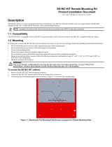
Ensure that all cable access ports located at the front bottom right and left sides are open
before complexing. See Figure 3-1.
When the task of complexing the console is finished, close the cable access port on each end
of the console.
11351
Shown in Open Position
Cabinet Front
Coax Cable
Channel
Figure 3-1 — Location of Cable Access Ports in a Universal Station

LCN System Installation 3-4 9/96
3.4
When Universal Stations (USs) are to be complexed together to form a console, use
complexing kit P-ZCKY1. The number of kits required for a console is one less than the
number of USs in the console. A complexing plate, 51303672, mounts on the bottom of
the keyboard, connecting the two keyboards together. See Figure 3-2.
11350
Complexing
Plate
US Keyboard on the Left
US Keyboard on the Right
Underside of Left Keyboard
Underside of Right Keyboard
Figure 3-2 — Installation of Complexing Plate under US Keyboard
/