
1
E114033#2
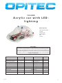
114.033
Acrylic car with LED-
lighting
Necessary tools:
Drills ø2/4 and 5mm
Fretsaw
Hot glue gun
Wire strippers
File
Scissors
PARTS LIST
Plastic car 1 130 Car 1
Light Emitting Diode 2 ø5 Lighting front 2
Flashing LED blue 2 ø5 Lighting front 3
FLashing LED red 2 ø5 Lighting rear 4
Connector 12pole. 1 1,5-2,5mm Wiring 5
Cable red 1 500 Wiring 6
Cable black 1 500 Wiring 7
Battery holder 1 Power source 8
Micro switch 1 19x6 Switch 9
Please Note
The OPITEC range of projects are not intended as toys for young children.
They are primarily intended as teaching aids for Design Technology and to
develop young peoples practical skills. They should not be attempted un-
less under the guidance of a qualified adult. They are not suitable for child-
ren under 3 yeas old as they may contain small parts that can be swallowed
- danger of suffocation.!

2
E114033#1
Instructions
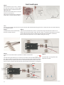
Step 1:
Take hold of the acrylic car (1) and drill
the two holes 5mm dia. in ( front lights ) !
Turn the car over and drill the two rear
lights 5mm dia.
The drill the two 5mm holes in the roof
5mm dai. 25 mm apart
Take the base make the the slot for the
switch (9) 12 x 6mm and le to shape.
Hole ø 5mm
Cut out for
switch
12x6 mm
Hole ø 5mm
Note:
Drill the acrylic slowly, otherwise the acrylic will split! We recommend drilling the holes in steps, rst a ø2, then ø4 and nally
use a ø5mm drill bit
Step 2:
Cut o from the connector block(6)
ve lots of 2 pole sections.
Step 3:
Glue the connector blocks (in twos -2-pole) with hot glue into the base of the car as
shown. Glue the micro switch (10) in the slot (12x6) , so that the connections are on the
inside. Glue the battery holder (8) between the two connector blocks at the front.
Note: If you want to paint the car, do it before adding the wiring!
Anode
Cathode
(side with at)
Cathode
(side with at)
Anode
Cathode
(side with at)
Anode
Anode
Cathode
(side with at)
Step 4:
The two white light diodes (2) are inserted in the front connector block (Battery hol-
der end) as shown and screwed in place. Note the position of the Anode and Catho-
de. Mount the two red LEDs (4) in the rear connector block (Switch side) and screw
them in place as shown. Note the position of the Anode and Cathode- see diagram )
Step 5:
The blue LEDs (3) are glued in the
top holes as shown
Insert the red and white LEDS in position as shown and bend the
legs.

3
E114033#2
Instructions
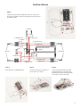
Step 6:
Connect up the various components with wire (6/7). Cut
the cable to length as shown (see diagram) strip the insulati-
on from the ends
ca. 60mm red
ca. 90mm black
ca. 40mm red
ca. 40mm
black
ca. 60mm black
ca. 60mm red
ca. 50mm red
ca. 80mm black
ca. 40mm red
ca. 30mm red
ca. 40mm
black
Battery cable ,shorten
ca. 50mm
Step 7:
Insert the (2x 1,5 V AAA) batteries.
Insert the rear LEDs (4, red) in the
holes at the rear chassis.
Step 8:
Insert the two front LEDs (2, white)
through the holes in the front and
then nish by pressing the top down
on the base -chassis. Finished!
Step 9:
LED blue
LED red
LED white
-
 1
1
-
 2
2
-
 3
3


Ask a question and I''ll find the answer in the document
Finding information in a document is now easier with AI
Related papers
Other documents
-
 Ultra Products Dual UV 80mm Round Cold Cathode Light Kit ULT31354 User manual
-
ABB CM-06DN Series User manual
-
 Geely FC Workshop Manual
-
Blaupunkt VY-VZ Installation Instructions Manual
-
Falcon SD-920R1S Manual Instruction
-
 Fujikura FSM–40S Maintenance Manual
-
Christie D4K35 User manual
-
Audiovox AA-RS20CS User manual
-
DFROBOT DFR0100 User guide
-
 Great Wall Pegasus 2006 Workshop User manual


