Page is loading ...

EN
II 2 G X T6
SERVICE MANUAL
READ ALL INSTRUCTIONS BEFORE OPERATING THIS DEVILBISS PRODUCT.
DEVILBISS AG360
Contact your local DeVilbiss representative for additional copies of this manual.
IMPORTANT! DO NOT DESTROY
It is the Customer's responsibility to have all operators and service personnel read and understand
this manual.
Low Pressure, Air Atomisation Automatic Spray
Gun, with Lever or Screw Type Manifold.
AG362
Series:
SB-E-2-643 R5.1 www.carlisleft.com

EN
P1=
P2=
P3=
P1=
1/8" G
P2=
1/8" G
P3=
1/8" G
Quickclean™ Coated Aluminium
WEIGHT
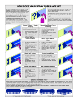
The AG362 low pressure air atomising spray guns are designed to be fast changeover, modular
construction applicators, for spray finishing on machines and fixed mountings.
The AG362 can be mounted on either a rear entry, lever operated, fast detachable manifold, or a
screw attached, low profile manifold, dependant on the part number selected and mounting
preference.
The AG362 is intended for most types of general industrial coating and fine finishing operations,
suitable for both water based and solvent based applications.
Guns are available with a range of Conventional, Trans-Tech (High Efficiency) and HVLP atomisation
air caps, to give a choice of atomisation and Transfer Efficiency parameters.
The gun is designed as a flexible solution for the modern coating applicator, with multiple accessories
available, to further optimise the process.
FLUID AND AIR INLET PRESSURES
ENVIRONMENTAL
MATERIALS OF CONSTRUCTION
Gun Head and Fluid Passageways
Air Inlet Size
Seals and O-Rings
HDPE, Viton Extreme
LEVER TYPE
LEVER TYPE
LEVER TYPE
SCREW TYPE
SCREW TYPE
SCREW TYPE
1/4" G
1/4" NPS
1/8" G
940g
850g
DIMENSIONS WITH MANIFOLD
Nitride Coated Stainless Steel
Fluid Inlet Size
Cylinder Inlet
FUNCTIONAL DESCRIPTION
SPECIFICATIONS
MANIFOLD CONNECTIONS
L x H x W mm
WEIGHT WITH MANIFOLD
127 x 97 x 44
127 x 64 x 89
7 Bar [102 psi]
7 Bar [102 psi]
Max Air Input Pressure
Max Fluid Input Pressure
Cylinder Air Pressure
4 - 7 Bar [58 psi - 102 psi]
40°C Nominal [104°F]
Max Ambient Operating Temperature
Electroless Nickel Plated Brass
Gun Body Material
Air Cap Material
Fluid Tip and Needle Construction
Stainless Steel
Stainless Steel
SB-E-2-643 R5.1 2/28 www.carlisleft.com

This Declaration of conformity /
incorporation is issued under the sole
responsiblity of the manufacturer:
Carlisle Fluid Technologies UK Ltd,
Ringwood Road,
Bournemouth, BH11 9LH. UK
EU Declaration of Conformity
Machinery Directive 2006/42/EC
ATEX Directive 2014/34/EU
by complying with the following statutory documents and harmonised standards:
EN ISO 12100:2010 Safety of Machinery - General Principles for Design
BS EN 1953:2013 Atomising and spraying equipment for coating materials - Safety requirements
EN 1127-1:2011 Explosive atmospheres - Explosion prevention - Basic concepts
EN 13463-1:2009 Non electrical equipment for use in potentially explosive atmospheres - Basic methods and
requirements
HVLP and High Efficiency products comply with the requirements of PG6 from the EPA guidelines and offer
greater than 65% transfer efficiency.
Providing all conditions of safe use / installation stated within the product manuals have been complied with and
also installed in accordance with any applicable local codes of practice.
Signed for and on behalf of Carlisle Fluid
Technologies UK Ltd:
D Smith
Director of Sales (EMEA)
20/4/16
Notified body details and role:
The object of the declaration described above is in conformity with the relevant Union
harmonisation legislation:
Protection Level:
Product Description / Object of Declaration:
AG362
This Product is designed for use with:
Solvent and water based materials
Suitable for use in hazardous area:
Zone 1 / Zone 2
II 2 G X T6
Element Materials Technology (0891)
Lodging of Technical file
SB-E-2-643 R5.1 3/28 www.carlisleft.com

EN
Important installation, operation or maintenance
information.
INSPECT THE EQUIPMENT DAILY. Inspect the equipment for
worn or broken parts on a daily basis. Do not operate the
equipment if you are uncertain about its condition.
FIRE AND EXPLOSION HAZARD. Never use 1,1,1-Trichloroethane,
Methylene Chloride, other Halogenated Hydrocarbon solvents or fluids
containing such solvents in equipment with aluminium wetted parts. Such use
could result in a serious chemical reaction, with the posibility of explosion.
Consult your fluid suppliers to ensure that the fluids being used are compatible
with aluminium parts.
STATIC CHARGE. Fluid may develop a static charge that must be dissipated
through proper grounding of the equipment, objects to be sprayed and all other
electrically conductive objects in the dispensing area. Improper grounding or
sparks can cause a hazardous condition and result in fire, explosion or elecrtic
shock and other serious injury.
TOXIC VAPOURS. When sprayed, certain materials may be poisonous, create
irritation, or are otherwise harmful to health. Always read all labels, safety
sheets and follow any recommendations for the material before spraying. If in
doubt contact your material supplier.
PRESSURE RELIEF PROCEDURE. Always follow the pressure
relief procedure in the equipment instruction manual.
Hazards or unsafe practices which could result in
severe personal injury, death or substantial
property damage.
OPERATOR TRAINING. All personnel must be trained before
operating finishing equipment.
LOCK OUT / TAG-OUT. Failure to de-energise, disconnect, lock out and tag-
out all power sources before performing equipment maintenance could cause
serious injury or death.
WEAR SAFETY GLASSES. Failure to wear safety glasses with
side shields could result in serious eye injury or blindness.
SOLVENTS AND COATING MATERIALS. Can be highly flammable or
combustible when sprayed. Always refer to the coating material supplier's
instructions and safety sheets before using this equipment.
READ THE MANUAL. Before operating finishing equipment, read and
understand all safety, operation and maintenance information provided in the
operation manual. Users must comply with all local and national codes of
practice and insurance company requirements governing ventilation, fire
precautions, operation and house-keeping of working areas.
Hazards or unsafe practices which could result in
minor personal injury, product or property
damage.
EQUIPMENT MISUSE HAZARD. Equipment misuse can cause
the equipment to rupture, malfunction or start unexpectedly and
result in serious injury.
WARNING
IT IS THE RESPONSIBILITY OF THE EMPLOYER TO PROVIDE THIS INFORMATION TO THE OPERATOR OF THE EQUIPMENT.
NOISE LEVELS. The A-weighted sound level of pumping and spray equipment
may exceed 85 dB(A) depending on equipment settings. Actual noise levels
are available on request. It is recommended that ear protection is worn at all
times while equipment is in use.
PROJECTILE HAZARD. You may be injured by venting liquids or
gases that are released under pressure, or flying debris.
CAUTION
Read the following warnings before using this equipment.
KNOW WHERE AND HOW TO SHUT OFF THE EQUIPMENT
IN CASE OF AN EMERGENCY.
GLOVES. Must be worn when spraying or cleaning the
equipment.
HIGH PRESSURE CONSIDERATION. High pressure can cause serious
injury. Relieve all pressure before servicing. Spray from the gun, hose leaks or
ruptured components can inject fluid into your body and cause extremely
serious injury.
WARNING
WEAR RESPIRATOR. The use of respiratory protective
equipment is recommended at all times. The type of equipment
must be compatible with the material being sprayed.
NEVER MODIFY THE EQUIPMENT. Do not modify the
equipment unless the manufacturer provides written approval.
In this part sheet, the words WARNING, CAUTION and NOTE are used to emphasise important safety information as
follows:
NOTE
SB-E-2-643 R5.1 4/28 www.carlisleft.com

EN
C
TE
HV
U - TE10 - 085N - L F P
U P
L F
S M
T
C1
C2
C3
TE10
TE20
TE30
TE40
TE50
HV30***
R40
*
**
***
Trans-Tech/Compliant
PRO-102-R40-K
110 L/min [4.0 cfm]
3 Bar [30 psi]
150-300 ml/min
70mm
Size & construction
GUN PART NUMBER FORMAT & PART SELECTION GUIDE
Fan pattern size @ 200mm distance.
375 L/min [13.3 cfm]
3 Bar [45 psi]
See table 2
150-250 ml/min
Typical Fluid
Flow*
Conventional
PRO-100-TE20-K
Ratchet
MANIFOLD TYPE
Trans-Tech/Compliant
PROC-120-C2-K
Conventional
Conventional
PRO-100-TE10-K
315mm
300mm
380mm
2 Bar [30 psi]
2 Bar [30 psi]
270mm
270mm
360mm
290mm
2 Bar [30 psi]
250-400 ml/min
100-350 ml/min
150-200 ml/min
200-300 ml/min
Trans-Tech/Compliant
2 Bar [30 psi]
PRO-100-HV30-K
PRO-100-TE50-K
Flow rates may vary according to paint/material and pressure used.
2 Bar [30 psi]
450 L/min [16.0 cfm]
250-400 ml/min
160-200 ml/min
425 L/min [15.1 cfm]
HV30 (HVLP) operates at 0.7 bar [10 psi] atomisation air pressure at the cap.
300mm
HVLP
PRO-100-TE40-K
Trans-Tech/Compliant
355 L/min [12.6 cfm]
Trans-Tech/Compliant
PRO-100-TE30-K
GUN HEAD FLUID PASSAGEWAYS
VALVE OPTIONS
BACK END OPTIONS
Control Valve
Plugged
Gun only
Screw manifold - recirculation
Lever manifold
Screw manifold - no recirculation
Fixed
Micrometer
Typical Fan
Pattern Size**
300 L/min [10.7 cfm]
3 Bar [45 psi]
325 L/min [11.6 cfm]
FLUID TIP
AIR CAP PERFORMANCE GUIDE
AG362
AG362
AIR CAP
250-600 ml/min
See table 1
Recommended
Air Inlet Pressure
PROC-120-C1-K
Air Cap & Type
Conventional
See pages 8 & 10
Single hole head feed
Head recirculation
HVLP
Trans-Tech/Compliant
TABLE 1
AG362
Part Number
PROC-120-C3-K
150-200 ml/min
Air Consumption
290 L/min [10.3 cfm]
440 L/min [15.7 cfm]
3 Bar [45 psi]
Trans-Tech/Compliant
2 Bar [30 psi]
255 L/min [9.1 cfm]
300mm
SB-E-2-643 R5.1 5/28 www.carlisleft.com

EN
- - SN SN SN SN SN SN - - -
- - SN SN SN SN SN SN - - -
- - SN SN SN SN SN SN - - -
- - SN SN SN SN SN SN SN SN -
- - SN SN SN SN SN SN SN SN -
- - SN SN SN SN SN SN SN SN -
- - SN SN SN SN SN SN SN SN -
- - SN SN SN SN SN SN SN SN -
- - SN SN SN SN SN SN SN SN -
- - SN SN SN SN SN SN SN SN -
S =
N =
R40
Trans-Tech
SPA-362N-085-10-K
SPA-362N-12-14-K
SPA-362N-16-18-K
SPA-362N-20-22-K
PRO-205-12-K
SPA-362-12-14-K
PRO-205N-14-K
PRO-205N-16-K
PRO-205-14-K
SPA-362-16-18-K
PRO-205-16-K
PRO-205-22-K
PRO-205-20-K
PRO-205N-20-K
2.0
PRO-205N-22-K
PRO-205-18-K
SPA-362-20-22-K
PRO-205N-18-K
For Conventional tip & needle part numbers, see table 3.
1.4
2.2
PROC-215N-12-K
SPA-362-12-14-K
SPA-362-16-18-K
1.0
1.8
1.6
SPA-362N-12-14-K
PROC-215N-14-K
PROC-215N-16-K
SPA-362N-16-18-K
PROC-215N-18-K
PRO-205-10-K
0.5mm
PROC-215N-10-K
2.0mm
AIR CAP
Atomisation Type
1.6mm
1.2mm
1.8mm
2.2mm
2.8mm
0.85
PRO-205N-085-K
PRO-205-085-K
HVLP
PROC-215-10-K
PROC-215-12-K
SPA-362-085-10-K
For Trans-Tech / HVLP tip & needle part numbers, see table 4.
0.85
1.0
1.2
HV30
1.4
1.6
Fluid Tip Size
PROC-215-085-K
Stainless Steel
Fluid Tip
Needle
Fluid Tip
Needle
PROC-215N-085-K
SPA-362N-085-10-K
TE40
PROC-215-14-K
PROC-215-16-K
Stainless Steel
Nitride Hardened
Needle
Nitride hardened tips & needles also available in this type & size.
1.4mm
PRO-205N-12-K
1.2
C3
TE40R
TE30
Trans-Tech
TABLE 3
High quality stainless steel tips & needles available in this type & size.
TE10
PRO-205N-10-K
SPA-362-085-10-K
1.8
PROC-215-18-K
Nitride Hardened
Fluid Tip
Needle
TABLE 2
TABLE 3
TABLE 4
AG362
RECOMMENDED FLUID TIP / AIR CAP COMBINATIONS
AG362
CONVENTIONAL FLUID TIPS & NEEDLES
AG362
TRANS-TECH / HVLP FLUID TIPS & NEEDLES
0.7mm
0.85mm
1.0mm
Trans-Tech
Conventional
Conventional
Conventional
Fluid Tip
C1
C2
Trans-Tech
TE20
Trans-Tech
Trans-Tech
SB-E-2-643 R5.1 6/28 www.carlisleft.com

EN
1
2
3
4
5 3/2
6
P1
P3
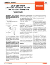
Compressed air take-off
Shut-off valve
CAP - 1/8" G
The spray gun must be earthed to dissipate any electrostatic charges which may be created by fluid
or air flows. This can be achieved through the spray gun mounting, or conductive air/fluid hoses.
Electrical bond from the spray gun to earth should be checked and a resistance of less than 10⁶ Ohms
is required.
CYL - 1/8" G
TYPICAL AIR CONNECTION SCHEMATIC - LEVER TYPE MANIFOLD
WARNING
Air regulator & gauge
Quick exhaust valve & silencer
Air filter
solenoid valve, normally closed
1
2
3
4
5
6
P3
P1
P1
SB-E-2-643 R5.1 7/28 www.carlisleft.com

EN
1
2
3
4
5
P2
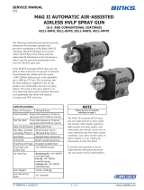
Shut-off valve
Fluid supply
FRONT VIEW
NOTE
AG362-XXXX-XXXX-L
Fluid filter
FRONT VIEW
AG362U-XXXX-XXXX-L
Protective coatings have been used for storage protection. Flush the equipment fluid passageways
with appropriate solvent before use.
Fluid restrictor valve
TYPICAL FLUID CONNECTION SCHEMATIC - LEVER TYPE MANIFOLD
Fluid reservoir
Fluid - 1/8" G
1
2
3
P2
4
5
P2
P2
SB-E-2-643 R5.1 8/28 www.carlisleft.com

EN
1
2
3
4
5 3/2
6
P1
P3
Shut-off valve
solenoid valve, normally closed
Air filter
WARNING
The spray gun must be earthed to dissipate any electrostatic charges which may be created by fluid
or air flows. This can be achieved through the spray gun mounting, or conductive air/fluid hoses.
Electrical bond from the spray gun to earth should be checked and a resistance of less than 10⁶ Ohms
is required.
Quick exhaust valve & silencer
Compressed air take-off
CAP - 1/4" G
CYL - 1/8" G
Air regulator & gauge
TYPICAL FLUID CONNECTION SCHEMATIC - SCREW TYPE MANIFOLD
1
2
3
4
5
6
P3
P1
SB-E-2-643 R5.1 9/28 www.carlisleft.com

EN
1
2
3
4
5
P2
Fluid filter
AG362-XXXX-XXXX-S
AG362U-XXXX-XXXX-S
AG362-XXXX-XXXX-T
FRONT VIEW
TYPICAL FLUID CONNECTION SCHEMATIC - SCREW TYPE MANIFOLD
Fluid restrictor valve
Fluid supply
FRONT VIEW
FRONT VIEW
Fluid - 1/4" NPS
Fluid reservoir
Shut-off valve
NOTE
Protective coatings have been used for storage protection. Flush the equipment fluid passageways
with appropriate solvent before use.
P2
P2
P2
P2
3
5
4
1
2
P2
SB-E-2-643 R5.1 10/28 www.carlisleft.com

EN
SPRAY GUN AND MANIFOLD INSTALLATION
SCREW TYPE MANIFOLD
LEVER TYPE MANIFOLD
AG362 -
AG362 -
SB-E-2-643 R5.1 11/28 www.carlisleft.com

EN
PARTS LIST
SPRAYHEAD & PIN ASSY
6
SN-18-1-K2
GASKET (KIT OF 2)
EXPLODED VIEW
1
DESCRIPTION
ASSEMBLY
QTY.
REF.
PART No.
1
SEE TABLE
AIR CAP & RETAINING RING
1
2
1
1
1
1
3
4
5
FLUID TIP
SN-69-K
SPA-152-K
HEAD
1
7
DESCRIPTION
RETAINING RING SUB ASSEMBLY
SPRING CLIP (KIT OF 5)
1
SPA-152U-K
RECIRCULATION HEAD
JGA-156-K5
PRO-405-K
SB-E-2-643 R5.1 12/28 www.carlisleft.com

EN
*
#
S-28225X-K2
10
PART No.
DESCRIPTION
1
O RING (KIT OF 2)
AIR VALVE PISTON (KIT OF 2)
12
13
S-28223X-K4
S-14192-K4
S-28224X-K4
O RING (KIT OF 4)
2
SPA-62-K2
16
PISTON & SEAL KIT
AIR TUBE
SPA-52
1
S-28220X-K2
SPA-60X-K
1
1
36
35
SPA-414-K
SPA-419UP-K
19
S-28219X-K4
SPA-13
23
24
NEEDLE SPRING KIT
O-RING (PART OF SPA-161-K2)
38
39
-
SPA-419U-K
RETAINING SCREW
HEXAGON SOCKET SET SCREW
MANIFOLD
RECIRCULATION SCREW MANIFOLD ASSEMBLY
CONTROL VALVE
LEVER MANIFOLD ASSEMBLY
SPRING BUTTON (KIT OF 2)
2
41
SEE TABLE
SPA-421-K
SPA-422-K2
SPA-165-K2
SPA-59
33*
REF.
34
1
BODY
PART OF KIT SPA-424-K
1
ASSEMBLY
QTY.
O RING (KIT OF 4)
PARTS LIST
6
8
SPA-29X-K4
SPA-153-K
SPA-159-K
9
1
14
15
32
11
17
18
20
O RING (KIT OF 4)
PISTON SPRING
SPA-415-K
1
28#
SPA-166-K
21#
22
1
NEEDLE PACKING
SPA-KK-1
27
SPA-424-K
SPA-418-K
-
31
ADJUSTING KNOB
29*
FIXED REAR HOUSING
40
SPA-160-K
30
LEVER MANIFOLD ASSEMBLY PLUGGED
SPA-418P-K
CLAMPING SCREW (KIT OF 2)
1
1
2
2
SPA-161-K2
42
SPA-167-K
O RING (KIT OF 4)
TORX SCREW (KIT OF 4)
SCREW MANIFOLD ASSEMBLY
1
MANIFOLD
1
1
LOCKING PIN (AG-362)
REAR HOUSING ASSEMBLY
1
1
4
1
1
1
1
O RING (KIT OF 2)
SPRING COLLAR (KIT OF 2)
1
NEEDLE SPRING
1
1
1
1
SPA-31
25
26
SPA-419-K
37
PART OF KIT SPA-426-K
SPA-419P-K
SCREW MANIFOLD ASSEMBLY PLUGGED
RECIRCULATION SCREW MANIFOLD ASSEMBLY PLUGGED
1
1
-
1
S-14193
1
LOCKING CAM
2
BLANKING PLUG
1
SPA-417-K
SPA-111-K2
MICROMETER ASSEMBLY
RING AND BALL KIT
FLUID NEEDLE
1
1
SB-E-2-643 R5.1 13/28 www.carlisleft.com

EN
1.
2.
1.
2.
3.
4.
5.
6.
7.
8.
9.
10.
11.
TYPICAL SETTING
The ATOM air valve controls the atomising air pressure, the FAN valve controls the spray
pattern size. To increase the pressure, turn anti-clockwise and to reduce the pressure turn
clockwise.
Fluid flow can be adjusted with the needle adjustment knob, fluid flow is increased when you
turn the knob anti-clockwise.
Turn the needle adjustment knob anti-clockwise until the needle is fully open.
Turn the FAN and ATOM air valves anti-clockwise to be fully open.
Trigger the gun and adjust the fluid supply pressure, to obtain the recommended fluid flow
shown in the air cap performance guide table.
Trigger the gun and set the gun inlet air pressure regulator, to achieve the recommended start
pressures, shown in the air cap performance guide table.
Test spray - if the finish is too dry or fine, reduce the air flow by reducing the air inlet pressure
or by screwing the ATOM valve in clockwise. Alternatively increase the fluid flow using the
fluid supply pressure.
Test spray - if the finish is too wet, reduce the fluid supply pressure to reduce the fluid flow.
Alternativeily increase the air inlet pressure to increase atomising pressure.
Use the needle adjustment knob for final fine tuning of the fluid flow.
The pattern size can be reduced by turning adjusting valve clockwise. A reduction in the spray
fan may require a reduction in fluid flow.
The spray pattern will be optimised when the spray gun is perpendicular to the target.
The recommended spray distance is normally 150-200mm. [6-8"]
Always turn off air and fluid supply, relieve pressure and clean down when gun is not in use.
TYPICAL START-UP SEQUENCE
SB-E-2-643 R5.1 14/28 www.carlisleft.com

EN
DISASSEMBLY TIP & NEEDLE
MAINTENANCE
Petroleum Grease/Jelly
Thread Sealant
Order for disassembly
(reverse for assembly)
Thread Locker
KEY - MAINTENANCE SYMBOLS
Item Number
#
#
SB-E-2-643 R5.1 15/28 www.carlisleft.com

EN
DISASSEMBLY PISTON
DISASSEMBLY PACKING
SB-E-2-643 R5.1 16/28 www.carlisleft.com

EN
When removing air cap from retaining ring, do not remove the ring seat from the retaining ring. Damage to the
parts may occur. Simply wipe parts clean and reassemble with new or clean air cap.
Paint build-up on fluid tip.
Replace with new air cap.
Gradual build-up of bounce-back on
gun head.
Incorrect needle fitted to gun.
Check tip/needle selection chart and
fit correct item.
Tighten.
Fluid tip/needle leakage.
Check for damage or blockage.
Excessive needle wear.
Fluid tip or sprayhead incorrectly
fitted.
Paint build-up on air cap.
Damaged air cap holes.
Remove, check components for
damage and refit correctly.
TROUBLESHOOTING MECHANICAL PERFORMANCE
Will not spray.
No air pressure at gun.
Check air supply and air line.
Fluid needle adjustment knob not
open enough.
Open fluid needle adjustment knob.
Gun spits paint when triggering on
and off.
Unable to get round spray
Gun spits paint when triggering on
due to paint build-up inside air cap
between spraying operations.
Fluid tip not fitted correctly in gun
head.
Fluid tip/needle leakage.
Tighten.
Thoroughly clean.
Fluid tip not fitted correctly in gun
head.
Check for damage or blockage.
CAUSE
CORRECTION
GENERAL FAULTS
Replace with new needle.
Excessive fluid tip wear.
Replace with new fluid tip.
SB-E-2-643 R5.1 17/28 www.carlisleft.com

EN
FLUID FAULTS
CORRECTION
Piston contaminated and not
correctly seating.
Contamination on needle or tip
mating surfaces preventing good
seal.
Adjust.
Contamination on needle or tip
mating surfaces preventing good
seal.
Incorrect fluid tip for fluid needle
fitted to gun.
Check tip/needle selection chart and
fit correct item.
Fluid needle external profile
damaged or worn.
Tight packing nut.
Thoroughly clean.
CAUSE
Major fluid leak or fluid jetting from
fluid tip and needle seat.
Small air leak from air cap when gun
is not triggered.
Fluid tip internal seat scored
damaged or worn.
Remove piston and thoroughly clean
valve shaft and seating surfaces.
Check tip/needle selection chart and
fit correct item.
Incorrect fluid tip for fluid needle
fitted to gun.
Sluggish needle.
CORRECTION
Piston seal damaged or missing.
Replace.
CAUSE
Replace.
Replace.
Tighten or replace as necesarry.
Fluid needle packing worn or loose.
Slow fluid leak from needle packing,
three possible places.
Remove tip and needle and
thoroughly clean.
Slow fluid leak from fluid tip and
needle seat.
Lubricate packing.
AIR FAULTS
SB-E-2-643 R5.1 18/28 www.carlisleft.com

EN
ASSEMBLY FAULTS
Turn locking cam lever to unlock
position on manifold.
Locking cam has not been tightened.
Locking cam has worn.
Remove item 29 - locking pin.
CAUSE
CORRECTION
LEVER TYPE MANIFOLD FAULTS
Tighten screw.
Turn locking cam lever to lock
position on manifold.
Replace using locking cam kit SPA-
424-K
CORRECTION
Spray gun cannot be removed from
manifold.
ASSEMBLY FAULTS
CAUSE
Remove clamping screw.
Clamping screw still in place.
Replace using clamping screw kit
SPA-161-K2.
Clamping screw has not been
tightened.
Spray gun is loose when assembled
onto manifold.
Item 29 - locking pin still in place.
Spray gun is loose when assembled
onto manifold.
SCREW TYPE MANIFOLD FAULTS
Spray gun does not locate onto
manifold.
Locking cam is not in the unlock
position.
Turn locking cam lever to unlock
position on manifold.
Locking cam is not in the unlock
position.
Spray gun does not locate onto
manifold.
Clamping screw has worn.
Spray gun cannot be removed from
manifold.
SB-E-2-643 R5.1 19/28 www.carlisleft.com

EN
Heavy right or left
side pattern.
Left or right side horn holes plugged.
Soak cap or tip in suitable solvent
and thoroughly clean.
Dirt or damage on left or right side
of fluid tip exterior.
Replace fluid tip or air cap if
necesarry.
Remedies for the top-heavy, bottom-heavy, right-heavy and left-heavy patterns.
Determine if the obstruction is on the air cap or the fluid tip. Do this by making a test spray pattern. Then, rotate
the cap one-half turn and spray another pattern. If the defect is inverted, obstruction is on the air cap. Clean the
air cap as previously instructed. Also check for dried paint just inside the cap centre hole opening, remove by
washing with solvent.
If the defect is not inverted, it is on the fluid tip. Clean tip. If problem persists, renew tip.
CAUSE
CORRECTION
Heavy top or bottom pattern.
Material build-up on air cap,
plugged horn holes, centre holes or
jets.
Soak cap or tip in suitable solvent
and thoroughly clean.
Material build-up on fluid tip exterior
or partially plugged fluid tip.
Replace fluid tip or air cap if
necesarry.
Fluid tip or cap dirty or damaged.
Replace fluid tip or air cap if
necesarry.
CONDITION
TROUBLESHOOTING SPRAY PERFORMANCE
SB-E-2-643 R5.1 20/28 www.carlisleft.com
/