Vertiv Liebert ITA2 Installation guide
- Type
- Installation guide
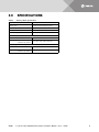
Vertiv Liebert ITA2 is a battery cabinet that can be used to extend the battery life of your Liebert ITA2 UPS. The battery cabinet is designed to be used with 8-10kVA, 60Hz, 208/220V UPS systems. It can accommodate up to 12 batteries, which can provide up to 10 minutes of runtime at full load. The battery cabinet is also equipped with a battery management system that monitors the status of the batteries and provides alarms in the event of a problem.
Here are some of the benefits of using a Vertiv Liebert ITA2 battery cabinet:
- Extended battery life: The battery cabinet can extend the battery life of your UPS by up to 10 minutes, giving you more time to safely shut down your equipment in the event of a power outage.


-
 1
1
-
 2
2
-
 3
3
-
 4
4
-
 5
5
-
 6
6
-
 7
7
-
 8
8
-
 9
9
-
 10
10
-
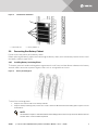 11
11
-
 12
12
-
 13
13
-
 14
14
-
 15
15
-
 16
16
-
 17
17
-
 18
18


Vertiv Liebert ITA2 Installation guide
- Type
- Installation guide
Vertiv Liebert ITA2 is a battery cabinet that can be used to extend the battery life of your Liebert ITA2 UPS. The battery cabinet is designed to be used with 8-10kVA, 60Hz, 208/220V UPS systems. It can accommodate up to 12 batteries, which can provide up to 10 minutes of runtime at full load. The battery cabinet is also equipped with a battery management system that monitors the status of the batteries and provides alarms in the event of a problem.
Here are some of the benefits of using a Vertiv Liebert ITA2 battery cabinet:
- Extended battery life: The battery cabinet can extend the battery life of your UPS by up to 10 minutes, giving you more time to safely shut down your equipment in the event of a power outage.
Ask a question and I''ll find the answer in the document
Finding information in a document is now easier with AI
Related papers
-
Vertiv Liebert ITA2 40kVA User manual
-
-
-
-
-
-
-
-
Vertiv Liebert® DSE 250-265 kW Thermal Management System User manual
-
Vertiv Liebert® XDM Chiller User manual
Other documents
-
Support Vertiv User guide
-
Liebert EXM BDC User manual
-
-
-
-
-
-
-
-