
Hundreds of Thousands of Lathes Sold With a Tradition of
Q
uality Since 1906!
© March, 2010 by South Bend Lathe Co. For Machines Mfg. Since 7/09
14" & 16" EVS TOOLROOM LATHES
MODELS SB1012/SB1014/SB1037 - 220V
MODELS SB1013/SB1015/SB1038 - 440V
OWNER'S MANUAL

Customer Service
We stand behind our machines. If you have any service questions, parts requests or general questions
about your purchase, feel free to contact us.
South Bend Lathe Co.
P.O. Box 2027
Bellingham, WA 98227
Fax: (360) 676-1075 (International)
Fax: (360) 734-1639 (USA Only)
Email: [email protected]
Updates
For your convenience, any updates to this manual will be available to download free of charge
through our website at:
www.southbendlathe.com
Scope of Manual
This manual helps the reader understand the machine, how to prepare it for operation, how to control
it during operation, and how to keep it in good working condition. We assume the reader has a basic
understanding of how to operate this type of machine, but that the reader is not familiar with the
controls and adjustments of this specific model. As with all machinery of this nature, learning the
nuances of operation is a process that happens through training and experience. If you are not an
experienced operator of this type of machinery, read through this entire manual, then learn more
from an experienced operator, schooling, or research before attempting operations. Following this
advice will help you avoid serious personal injury and get the best results from your work.
Manual Feedback
We've made every effort to be accurate when documenting this machine. However, errors sometimes
happen or the machine design changes after the documentation process—so the manual may not
exactly match your machine. If a difference between the manual and machine leaves you in doubt,
contact our customer service for clarification.
We highly value customer feedback on our manuals. If you have a moment, please share your
experience using this manual. What did you like about it? Is there anything you would change to
make it better? Did it meet your expectations for clarity, professionalism, and ease-of-use?
South Bend Lathe, Inc.
C
/O Technical Documentation Manager
P.O. Box 2027
Bellingham, WA 98227
Email: [email protected]

Table of Contents
INTRODUCTION .................................................... 3
About These Machines.........................................3
Foreword ............................................................. 3
Capabilities .........................................................3
Features ..............................................................3
Identification ........................................................ 4
SAFETY ..................................................................5
Understanding Risks of Machinery ....................5
Basic Machine Safety .......................................... 5
Additional Metal Lathe Safety ............................7
PREPARATION ...................................................... 8
Preparation Overview ..........................................8
Things You'll Need ...............................................8
Unpacking ............................................................8
Inventory ..............................................................9
Cleaning & Protecting ....................................... 10
Location ..............................................................11
Physical Environment ........................................ 11
Electrical Installation ........................................11
Lighting ............................................................11
Weight Load ...................................................... 11
Space Allocation ................................................11
Lifting & Moving ................................................ 12
Leveling & Mounting .........................................13
Leveling ............................................................13
Bolting to Concrete Floors ..................................14
Assembly ............................................................14
Lubricating Lathe ..............................................14
Adding Cutting Fluid .........................................15
Power Connection ..............................................15
SB1012 (220V 3-Phase) ......................................15
SB1014, SB1037 (220V 3-Phase) ........................... 15
SB1013 (440V 3-Phase) .......................................... 15
SB1015, SB1038 (440V 3-Phase) ........................... 15
Connecting Power Cord to Lathe ........................ 16
Hardwiring Lathe to Power Source ....................16
Correcting Out-of-Phase Wiring .........................17
Test Run .............................................................17
Spindle Break-In ................................................21
Recommended Adjustments .............................. 22
OPERATION ........................................................23
Operation Overview ........................................... 23
Description of Controls & Components ............24
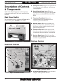
Main Power Switch ............................................24
Headstock Controls ............................................ 24
Carriage Controls ..............................................24
Control Panel ....................................................25
Tailstock Controls .............................................. 26
Foot Brake ........................................................26
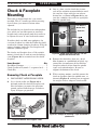
Chuck & Faceplate Mounting ...........................27
Removing Chuck or Faceplate ............................ 27
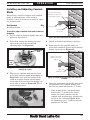
Mounting Chuck or Faceplate ............................28
Installing and Adjusting Camlock Studs ............. 29
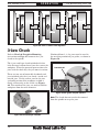
3-Jaw Chuck ....................................................... 30
Changing Jaws .................................................. 31
Mounting Workpiece ..........................................31
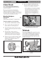
4-Jaw Chuck ....................................................... 32
Mounting Workpiece ..........................................32
Tailstock .............................................................32
Moving Along Bedway .......................................33
Using Quill ........................................................33
Installing Tooling ..............................................33
Removing Tooling ..............................................33
Offsetting ..........................................................34
Aligning ............................................................34
Faceplate ............................................................36
Mounting Workpiece with Clamps ......................36
Mounting Workpiece Between Centers ............... 36
Centers ...............................................................37
Dead Centers .....................................................37
Live Centers ...................................................... 37
Mounting Dead Center in Spindle ......................37
Removing Center from Spindle ........................... 38
Mounting Center in Tailstock ............................. 38
Removing Center from Tailstock ........................38
Steady Rest ........................................................ 39
Follow Rest .........................................................39
Compound Slide ................................................. 40
Four-Way Tool Post ........................................... 40
Aligning Cutting Tool with Tailstock Center ....... 41
Aligning Cutting Tool with Tailstock Center ....... 41
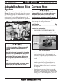
Adjustable Apron Stop System .........................42
Carriage Stop .....................................................42
Manual Feed ......................................................43
Carriage Handwheel ..........................................43
Compound Slide Handwheel ..............................43
Spindle Speed .....................................................43
Determining Spindle Speed ................................ 43
Setting Spindle Speed ........................................ 44

Power Feed ......................................................... 44
Power Feed Controls ..........................................45
Understanding Thread & Feed Rate Chart ......... 46
Positioning Gearbox Levers ................................ 46
End Gear Setup ................................................. 47
Threading Controls ............................................48
Power Feed Lever ..............................................48
Half Nut Lever ..................................................48
Thread Dial & Chart Overview ..........................48
Using Thread Dial and Chart .............................49
Chip Drawer ....................................................... 50
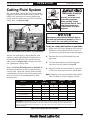
Cutting Fluid System ........................................ 51
ACCESSORIES ...................................................52
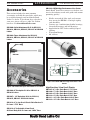
Accessories .........................................................52
MAINTENANCE ...................................................54
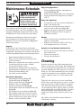
Maintenance Schedule .......................................54
Cleaning .............................................................54
Maintenance Chart ............................................55
Lubrication ......................................................... 56
Headstock .........................................................56
Gearbox .............................................................58
Apron ................................................................ 58
Lead Screw & Feedrod Bearings ........................59
Lead Screw ........................................................59
Ways & Slides ...................................................59
Unpainted & Machined Surfaces ........................59
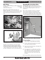
Ball Oilers ......................................................... 60
Cleaning Electrical Box Filter ............................60
End Gearing ..................................................... 61
Cutting Fluid System ........................................ 62
Hazards.............................................................62
Adding Fluid .....................................................62
Changing Cutting Fluid ..................................... 63
Machine Storage ................................................64
SERVICE .............................................................. 65
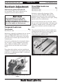
Backlash Adjustment ........................................ 65
Compound Leadscrew ........................................ 65
Cross Slide Leadscrew .......................................65
Leadscrew End Play Adjustment ......................66
Gib Adjustment ..................................................66
Half Nut Adjustment ......................................... 67
Feedrod Clutch Adjustment ..............................68
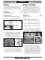
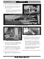
V-Belts ................................................................ 69
Brake & Switch .................................................. 69
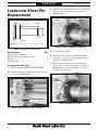
Leadscrew Shear Pin Replacement ..................71
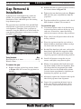
Gap Removal & Installation ..............................73
TROUBLESHOOTING ......................................... 74
WARRANTY & RETURNS ...................................77
16" South Bend Precision Toolroom Lathe (Circa 1958)

INTRODUCTION
For Machines Mfg. Since 7/09 EVS Toolroom Lathes
-3-
INTRODUCTION
About These Machines
Foreword
"The screw cutting engine lathe is the oldest and
most important of machine tools and from it all
other machine tools have been developed. It was
the lathe that made possible the building of the
steamboat, the locomotive, the electric motor, the
automobile and all kinds of machinery used in
industry. Without the lathe our great industrial
progress of the last century would have been
impossible." —How To Run a Lathe, 15th
Edition, South Bend Lathe.
The lathes represented in this manual are a
modern day version of the screw cutting lathes
that trace their roots back to the 1700's, which
were themselves technological improvements of
the bow lathe that can be traced back thousands
of years to the ancient Egyptians.
Now, almost 300 years later, these modern
"screw cutting" lathes are not just a piece of
refined machinery, but a culmination of human
ingenuity and knowledge embodied into the
design and synergy of thousands of interworking
parts—some of which represent the life's work
and dreams of many inventors, mechanical
engineers, and world-class machinists—including
the likes of Leonardo da Vinci, Henry Maudsley,
and the founders of South Bend Lathe, John and
Miles O'Brien.
And now the torch is passed to you—to take
the oldest and most important type of machine
tool—and carry on the tradition. As the operator
of a South Bend Lathe, you now join the ranks
of some very famous and important customers,
such as Henry Ford, who used the machines he
purchased to help him change the world.
Features
As the name implies, these lathes feature EVS
(Electronic Variable Speed) spindle control,
which allows the operator to quickly set the
exact spindle speed within the available range of
20–2500 RPM. Spindle speed is displayed on a
digital readout and controlled within each speed
range with the use of a dial—no changing gears
or looking up complex lever positions on a chart.
The beds of these lathes are constructed with
Meehanite castings that have been precision
hardened and ground in the traditional 3-V
prismatic design—long used on South Bend
Lathes for its accuracy, durability, and rigidity.
The headstock features quick-change gear levers
and an adjustable clutch mechanism for the feed
rod that can be set to prevent damage in the
event of a crash.
To further ensure a high degree of accuracy,
these lathes are equipped with NSK or NTN
spindle bearings. The spindles are the D1-6
camlock type with an MT#6 taper and 2.0625"
bore. The tailstock quills have an MT#4 taper
and offer 6" of travel.
The EVS lathes also include a pressurized
headstock oiling system that pre-lubricates
bearings/gears before the spindle starts and
delivers perfect lubrication during low speed
operations (compare to conventional splash
and bath oil systems that leave bearings/gears
starved for oil when the spindle is first started
and during low speed operations).
Finally, these EVS toolroom lathes are packed
with standard features, such as a complete
coolant system, easy-to-clean chip drawer, one-
shot way lubrication system, included steady and
follow rests, adjustable work lamp, foot brake,
and powered cross feed.
Capabilities
These EVS Toolroom Lathes are built for daily
use in a busy industrial setting. Loaded with
many nice features and high-precision parts,
these lathes excel at making fine tools, dies,
thread gauges, jigs, and precision test gauges—
however, they are by no means delicate. Thick
castings, heavy weight, and quality construction
throughout provide the necessary brawn for
demanding production and manufacturing tasks.

-4-
For Machines Mfg. Since 7/09
EVS Toolroom Lathes
INTRODUCTION
Identification
Serious personal injury could occur if
you connect the machine to power before
completing the setup process. DO NOT
connect power until instructed to do so later
in this manual.
Untrained users have an increased risk
of seriously injuring themselves with this
machine. Do not operate this machine until
you have understood this entire manual and
received proper training.
O. Leadscrew Bearing Housing
P. Cutting Fluid Pump/Tank
Q. Spindle Rotation ON/OFF Lever
R. Half Nut Lever
S. Apron Oil Level Sight Glass
T. Quick Change Apron Feed Direction Knob
U. Manual Way Oil Pump
V. Brake Pedal
W. Feed Control Lever
X. Apron Handwheel
Y. Cross Slide Handwheel
Z. Removable Chip Drawer
AA. Micrometer Stop
AB. Quick Change Gearbox
A. Headstock
B. D1-6 Camlock MT#6 Spindle
C. Control Panel
D. Ball Bearing Style Steady Rest
E. 4-Position Tool Holder
F. Follow Rest
G. Compound Slide
H. Compound Slide Handwheel
I. Work Lamp
J. Universal Cutting Fluid Tube and Nozzle
K. Cross Slide
L. Tailstock
M. Tailstock Handwheel
N. Thread Dial
A
B
C
D
E
F
H
L
K
M
O
Figure 1. The 14" & 16" EVS Lathe.
Y
V
X
Z
Q
P
N
R
W
T
U
S
I
J
G
AB
AA

SAFETY
For Machines Mfg. Since 7/09 EVS Toolroom Lathes
-5-
SAFETY
Understanding Risks of Machinery
Operating all machinery and machining equipment can be dangerous or relatively safe depending
on how it is installed and maintained, and the operator's experience, common sense, risk awareness,
working conditions, and use of personal protective equipment (safety glasses, respirators, etc.).
The owner of this machinery or equipment is ultimately responsible for its safe use. This
responsibility includes proper installation in a safe environment, personnel training and usage
authorization, regular inspection and maintenance, manual availability and comprehension,
application of safety devices, integrity of cutting tools or accessories, and the usage of approved
personal protective equipment by all operators and bystanders.
The manufacturer of this machinery or equipment will not be held liable for injury or property
damage from negligence, improper training, machine modifications, or misuse. Failure to read,
understand, and follow the manual and safety labels may result in serious personal injury, including
amputation, broken bones, electrocution, or death.
The signals used in this manual to identify hazard levels are defined as follows:
Death or catastrophic
harm WILL occur.
Moderate injury or fire
MAY occur.
Death or catastrophic
harm COULD occur.
Machine or property
damage may occur.
Basic Machine Safety
1. Owner’s Manual: All machinery and
machining equipment presents serious
injury hazards to untrained users. To
reduce the risk of injury, anyone who uses
THIS item MUST read and understand
this entire manual before starting.
2. Personal Protective Equipment:
Operating
or servicing this item may expose the user
to flying debris, dust, smoke, dangerous
chemicals, or loud noises. These hazards
can result in eye injury, blindness, long-
term respiratory damage, poisoning,
cancer, reproductive harm or hearing loss.
Reduce your risks from these hazards
by wearing approved eye protection,
respirator, gloves, or hearing protection.
3. Trained/Supervised Operators Only:
Untrained users can seriously injure
themselves or bystanders. Only allow
trained and properly supervised personnel
to operate this item. Make sure safe
operation instructions are clearly
understood. If electrically powered, use
padlocks and master switches, and remove
start switch keys to prevent unauthorized
use or accidental starting.
4. Guards/Covers:
Accidental contact with
moving parts during operation may cause
severe entanglement, impact, cutting,
or crushing injuries. Reduce this risk by
keeping any included guards/covers/doors
installed, fully functional, and positioned
for maximum protection.

-6-
For Machines Mfg. Since 7/09
EVS Toolroom Lathes
SAFETY
5. Entanglement: Loose clothing, gloves,
neckties, jewelry or long hair may
get caught in moving parts, causing
entanglement, amputation, crushing,
or strangulation. Reduce this risk by
removing/securing these items so they
cannot contact moving parts.
6. Mental Alertness: Operating this item
with reduced mental alertness increases
the risk of accidental injury. Do not let a
temporary influence or distraction lead to a
permanent disability! Never operate when
under the influence of drugs/alcohol, when
tired, or otherwise distracted.
7. Safe Environment:
Operating electrically
powered equipment in a wet environment
may result in electrocution; operating near
highly flammable materials may result in a
fire or explosion. Only operate this item in
a dry location that is free from flammable
materials.
8. Electrical Connection: With electically
powered equipment, improper connections
to the power source may result in
electrocution or fire. Always adhere to all
electrical requirements and applicable
codes when connecting to the power source.
Have all work inspected by a qualified
electrician to minimize risk.
9. Disconnect Power: Adjusting or servicing
electrically powered equipment while it
is connected to the power source greatly
increases the risk of injury from accidental
startup. Always disconnect power
BEFORE any service or adjustments,
including changing blades or other tooling.
10. Secure Workpiece/Tooling:
Loose
workpieces, cutting tools, or rotating
spindles can become dangerous projectiles
if not secured or if they hit another object
during operation. Reduce the risk of this
hazard by verifying that all fastening
devices are properly secured and items
attached to spindles have enough clearance
to safely rotate.
11. Chuck Keys or Adjusting Tools:
Tools used
to adjust spindles, chucks, or any moving/
rotating parts will become dangerous
projectiles if left in place when the machine
is started. Reduce this risk by developing
the habit of always removing these tools
immediately after using them.
12. Work Area:
Clutter and dark shadows
increase the risks of accidental injury.
Only operate this item in a clean, non-
glaring, and well-lighted work area.
13. Properly Functioning Equipment:
Poorly
maintained, damaged, or malfunctioning
equipment has higher risks of causing
serious personal injury compared to
those that are properly maintained.
To reduce this risk, always maintain
this item to the highest standards and
promptly repair/service a damaged or
malfunctioning component. Always follow
the maintenance instructions included in
this documentation.
14. Unattended Operation:
Electrically
powered equipment that is left unattended
while running cannot be controlled and is
dangerous to bystanders. Always turn the
power OFF before walking away.
15. Health Hazards: Certain cutting fluids
and lubricants, or dust/smoke created
when cutting, may contain chemicals
known to the State of California to cause
cancer, respiratory problems, birth defects,
or other reproductive harm. Minimize
exposure to these chemicals by wearing
approved personal protective equipment
and operating in a well ventilated area.
16. Difficult Operations:
Attempting
difficult operations with which you are
unfamiliar increases the risk of injury.
If you experience difficulties performing
the intended operation, STOP! Seek an
alternative method to accomplish the
same task, ask a qualified expert how the
operation should be performed, or contact
our Technical Support for assistance.

For Machines Mfg. Since 7/09 EVS Toolroom Lathes
-7-
SAFETY
Additional Metal Lathe Safety
7. Speed Rates. Operating the lathe at the
wrong speed can cause nearby parts to break
or the workpiece to come loose, which will
result in dangerous projectiles that could
cause severe impact injury. Large workpieces
must be turned at slow speeds. Always use
the appropriate feed and speed rates.
8. Stopping Spindle by Hand. Stopping the spin-
dle by putting your hand on the workpiece or
chuck creates an extreme risk of entangle-
ment, impact, crushing, friction, or cutting
hazards. Never attempt to slow or stop the
lathe spindle with your hand. Allow the
spindle to come to a stop on its own or use the
brake (if equipped).
9. Crashes. Driving the cutting tool or other
lathe components into the chuck may cause
an explosion of metal fragments, which can
result in severe impact injuries and major
damage to the lathe. Reduce this risk by
releasing automatic feeds after use, not leav-
ing lathe unattended, and checking clear-
ances before starting the lathe. Make sure no
part of the tool, tool holder, compound slide,
cross slide, or carriage will contact the chuck
during operation.
10. Long Stock Safety. Long stock can whip vio-
lently if not properly supported, causing seri-
ous impact injury and damage to the lathe.
Reduce this risk by supporting any stock that
extends from the chuck/headstock more than
three times its own diameter. Always turn
long stock at slow speeds.
11. Coolant Safety. Contaminated cutting fluid
is a very poisonous biohazard that can cause
personal injury from skin contact alone.
Incorrectly positioned cutting fluid nozzles
can splash on the operator or the floor,
resulting in an exposure or slipping hazard.
To decrease your risk, change cutting fluid
regularly and position the cutting fluid nozzle
where it will not splash or end up on the
floor.
1. Clearing Chips. Metal chips can easily cut
bare skin—even through a piece of cloth.
Avoid clearing chips by hand or with a rag.
Use a brush or vacuum to clear metal chips.
2. Chuck Key Safety. A chuck key left in the
chuck can become a deadly projectile when
the spindle is started. Always remove the
chuck key after using it. Develop a habit of
not taking your hand off of a chuck key unless
it is away from the machine.
3. Tool Selection. Cutting with an incorrect
or dull tool increases the risk of accidental
injury because extra force is required for the
operation, which increases risk of breaking
or dislodging components, which can cause
small shards of metal to become dangerous
projectiles. Always select the right cutter for
the job and make sure it is sharp. A correct,
sharp tool decreases strain and provides a
better finish.
4. Securing Workpiece. An improperly secured
workpiece can fly off of the lathe spindle with
deadly force, which can result in a severe
impact injury. Make sure the workpiece is
properly secured in the chuck or faceplate
before starting the lathe.
5. Large Chucks. Large chucks are very heavy
and difficult to grasp, which can lead to
crushed fingers or hands if mishandled. Get
assistance when installing or removing large
chucks to reduce this risk. Protect your hands
and the precision-ground ways by using a
chuck cradle or piece of plywood over the
ways of the lathe when servicing chucks.
6. Safe Clearances. Workpieces that crash into
other components on the lathe may throw
dangerous projectiles in all directions, lead-
ing to impact injury and damaged equipment.
Before starting the spindle, make sure the
workpiece has adequate clearance by hand-
rotating it through its entire range of motion.
Also, check the tool and tool post clearance,
chuck clearance, and saddle clearance.

PREPARATION
-8-
For Machines Mfg. Since 7/09
EVS Toolroom Lathes
PREPARATION
Preparation Overview Things You'll Need
To complete the preparation process, you will
need the following items:
For Lifting and Moving
s !&ORKLIFTOR/THER0OWER,IFTING$EVICE
(rated for at least 5000 lbs).
s ,IFTING3TRAP or Chain with Hook
(rated for at least 5000 lbs.)
s Helper for moving machine.
s Two 12" 2x6's
s 0RECISION,EVEL
For Power Connection
s !QUALIFIEDELECTRICIANTOENSUREASAFEAND
code-compliant connection to the power
source. (Refer to Page 15 for details.)
For Assembly
s Cotton Rags
s Mineral Spirits
s Quality Metal Protectant Oil
s 3AFETY'LASSES
s Wrench or Socket 21mm
s Wrench or Socket 19mm
s &LOOR-OUNTING(ARDWARE as Needed
s Standard Screwdriver #2
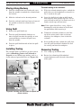
Unpacking
This item was carefully packaged to prevent
damage during transport. If you discover any
damage, please immediately call Customer
Service at (360) 734-1540 for advice. You may
need to file a freight claim, so save the containers
and all packing materials for possible inspection
by the carrier or its agent.
The purpose of the preparation section is to help
you prepare your machine for operation. The
list below outlines the basic process to follow to
prepare the lathe for operation. Specific steps for
each of these points will be covered in detail later
in this section.
The typical preparation process is as follows:
1. Unpack the lathe and inventory the contents
of the box/crate.
2. Clean the lathe and its components.
3. Identify an acceptable location for the lathe
and move it to that location.
4. Level the lathe and either bolt it to the floor
or place it on mounts.
5. Assemble the loose components and make
any necessary adjustments or inspections to
ensure the lathe is ready for operation.
6. Connect the lathe to the power source.
7. Test run the lathe to make sure it functions
properly and is ready for operation.

For Machines Mfg. Since 7/09 EVS Toolroom Lathes
-9-
PREPARATION
Inventory
Main Inventory 1: (Figure 2) Qty
A. Steady Rest Assembly .................................... 1
B. 12" Faceplate w/D1-6 Camlock Stud Set ...... 1
C. 10" Four-Jaw Chuck w/Combo Jaws .............1
D. Four-Jaw Chuck Key ..................................... 1
E. Four-Jaw Chuck D1-6 Camlock Stud Set ..... 1
F. Follow Rest Assembly ....................................1
Tool Box Inventory: (Figure 3) Qty
G. Tool Box ..........................................................1
H. Three-Jaw Chuck Key ................................... 1
I. Tool Post T-Wrench ........................................ 1
J. Hex Wrench Set 1.5-10mm ............................ 1
K. Dead Center MT#4 .........................................1
L. Carbide-Tipped Dead Center MT#4 ..............1
M. Tapered Spindle Sleeve MT#6-#4 .................1
N. Open End Wrench 22/24mm ......................... 1
O. Open End Wrench 14/17mm ......................... 1
P. Open End Wrench 10/12mm ......................... 1
Q. Phillips Screwdriver #2 .................................1
R. Standard Screwdriver #2 ...............................1
S. 9"-Chuck Jaws (SB1014-15, SB1037-38) ......3
8"-Chuck Jaws (SB1012-13) .......................... 3
T. Cast Iron Leveling Pads ................................ 8
U. Handwheel Handles .......................................2
Note: Some inventory components may be
shipped inside of the lathe electrical box. These
items MUST be removed before connecting the
lathe to the power source.
Figure 2. Main inventory.
Figure 3. Toolbox inventory.
A
B
C
D
E
F
G
H
I
J
K
L
M
N
O
P
Q
R
S
T
U

-10-
For Machines Mfg. Since 7/09
EVS Toolroom Lathes
PREPARATION
The unpainted surfaces are coated at the factory
with a heavy-duty rust preventative that
prevents corrosion during shipment and storage.
The benefit of this rust preventative is that it
works very well. The downside is that it can be
time-consuming to thoroughly remove.
Be patient and do a careful job when cleaning
and removing the rust preventative. The time
you spend doing this will reward you with
smooth-sliding parts and a better appreciation
for the proper care of the unpainted surfaces.
A
lthough there are many ways to successfully
remove the rust preventative, we have cleaned
thousands of machines and found the following
process to be the best balance between efficiency
and minimized exposure to toxic fumes or
chemicals.
Before cleaning, gather the following:
s $ISPOSABLErags
s #LEANERDEGREASER (certain citrus-based
degreasers work extremely well and they
have non-toxic fumes)
s 3AFETYGLASSESDISPOSABLEGLOVES
Note: Automotive degreasers, mineral spirits, or
7$sCANBEUSEDTOREMOVERUSTPREVENTATIVE
Before using these products, though, test them
on an inconspicuous area of a painted area to
make sure they will not damage it.
Basic steps for removing rust preventative:
1. Put on safety glasses and disposable gloves.
2. #OATALLSURFACESTHATHAVERUSTPREVENTATIVE
with a liberal amount of your cleaner or
degreaser and let them soak for a few
minutes.
3. Wipe off the surfaces. If your cleaner or
degreaser is effective, the rust preventative
will wipe off easily.
Note: To clean off thick coats of rust preventative
on flat surfaces, such as beds or tables, use
A0,!34)#PAINTSCRAPERTOSCRAPEOFFTHE
majority of the coating before wiping it off
WITHYOURRAG$ONOTUSEAMETALSCRAPEROR
it may scratch the surface.)
4. Repeat Steps 2–3 as necessary until clean,
then coat all unpainted surfaces with a
quality metal protectant or light oil to
prevent rust.
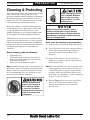
GAS
Gasoline and petroleum
products have low flash
points and can explode
or cause fire if used for
cleaning. Avoid using these
products to remove rust
preventative.
Many cleaning solvents are
toxic if inhaled. Minimize
your risk by only using
these products in a well
ventilated area.
Avoid chlorine-based solvents, such as
acetone or brake parts cleaner that may
damage painted surfaces. Always follow the
manufacturer’s instructions when using any
type of cleaning product.
Cleaning & Protecting

For Machines Mfg. Since 7/09 EVS Toolroom Lathes
-11-
PREPARATION
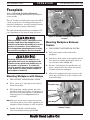
Keep
Workpiece
Loading Area
Unobstructed
Lathe
Electrical
Access
Door
= Power Connection Location
B
C
A
D
Min. 30"
Wall
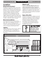
Figure 4. Space required for full range of movement.
SB1012-13
SB1014-15
SB1037-38
A
90" 109" 90"
B
60" 60" 60"
C
112" 130" 112"
D
20
1
⁄2"20
1
⁄2"20
1
⁄2"
Physical Environment
Electrical Installation
Lighting
Weight Load
Space Allocation
Weight Load
Refer to the Machine Specifications for the
weight of your machine. Make sure that the
surface upon which the machine is placed will
bear the weight of the machine, additional
equipment that may be installed on the machine,
and the heaviest workpiece that will be used.
Additionally, consider the weight of the operator
and any dynamic loading that may occur when
operating the machine.
Space Allocation
Consider the largest size of workpiece that will
be processed through this machine and provide
enough space around the machine for adequate
operator material handling or the installation
of auxiliary equipment. With permanent
installations, leave enough space around
the machine to open or remove doors/covers
as required by the maintenance and service
described in this manual.
Physical Environment
The physical environment where your machine
is operated is important for safe operation and
longevity of parts. For best results, operate this
machine in a dry environment that is free from
excessive moisture, hazardous or flammable
chemicals, airborne abrasives, or extreme
conditions. Extreme conditions for this type
of machinery are generally those where the
ambient temperature is outside the range of 41°–
104°F; the relative humidity is outside the range
of 20–95% (non-condensing); or the environment
is subject to vibration, shocks, or bumps.
Electrical Installation
Place this machine near an existing power
source. Make sure all power cords are protected
from traffic, material handling, moisture,
chemicals, or other hazards. Make sure to leave
access to a means of disconnecting the power
source or engaging a lockout/tagout device.
Lighting
Lighting around the machine must be adequate
enough that operations can be performed
safely. Shadows, glare, or strobe effects that
may distract or impede the operator must be
eliminated.
Children or untrained
people may be seriously
injured by this machine.
Only install in an access
restricted location.
Location

-12-
For Machines Mfg. Since 7/09
EVS Toolroom Lathes
PREPARATION
Lifting & Moving
Do not attempt to lift or move this lathe if you do
not have the proper equipment or the necessary
assistance from other people. All lifting
equipment must be rated to at least 5,000 lbs.
to account for dynamic loads from bouncing or
pulling that may be applied while lifting. Refer
to the Things You'll Need section on Page 8 for
details.
To lift and move your lathe:
1. Prepare the permanent location for the
lathe.
2. Remove the shipping crate top and sides,
then remove the small components from the
shipping pallet.
3. To balance the lifting load, loosen the
tailstock lock lever (Figure 5), move the
tailstock to the end of the bedway, then lock
it in place.
This machine and its
parts are heavy! Serious
personal injury may occur
if safe moving methods are
not used. To reduce the
risk of a lifting or dropping
injury, ask others for help
and use power equipment.
4. To further balance the load, loosen the
carriage lock bolt (see Figure 6), disengage
the half nut lever, put the feed control lever
in neutral, then use the carriage handwheel
to move the carriage next to the tailstock.
Figure 5. Tailstock lock lever.
Tailstock Lock Lever
5. Position a 12" long 2x6 board under each end
of the bed, as shown in Figure 7, wrap the
lifting straps around the bottom of the 2x6's.
Note: The 2x6's extend the lifting straps away
from the bottom of the bed to prevent
machine damage from excessive strap
pressure against the leadscrew, feed rod, and
spindle control rod. Make sure to use them.
12" Long
2x6 Board
Lifting
Strap
Lathe
Bed
Leadscrew
Feed Rod
Spindle
Control
Rod
To Forklift or Lifting Hook
(Cross-Section View of Lifting Setup)
Figure 7. Cross section of lifting setup to keep strap
from putting pressure against leadscrew or rods.
Figure 6. Carriage controls set for moving the carriage.
Lock Bolt
Engaged
HALF NUT
LEVER
Disengaged
Cross Slide
Neutral
FEED CONTROL
LEVER
Carriage
Feed Control Lever
Half Nut Lever
Carriage
Handwheel

For Machines Mfg. Since 7/09 EVS Toolroom Lathes
-13-
PREPARATION
6. Attach the lifting straps to forklift forks or a
hook and chain, as shown in Figures 8–9.
Forklift
Forks
Lifting
Straps
12" Long
2x6 Board
12" Long
2x6 Board
Figure 8. Lathe set up for lifting with forklift.
7. Unbolt the lathe from the shipping pallet,
then with an assistant to help keep the lathe
from swaying, raise the lathe a couple of
inches.
— If the load is not well balanced, or you
see any other difficulties with the lifting
equipment, immediately lower the lathe
to the pallet again. Resolve any lifting or
balancing issues, then repeat this step.
8. With assistance to steady the load, move it to
the prepared location and lower it in place.
Lifting Hook
with Chain
Lifting
Straps
12" Long
2x6 Board
12" Long
2x6 Board
Figure 9. Lathe set up for lifting with hook and chain.
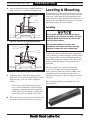
Leveling & Mounting
You must level your machine and either use the
included foot pads and leveling hardware or bolt
your lathe to the floor. Because mounting your
lathe to the floor with permanent hardware is an
optional step and floor materials may vary, floor
mounting hardware is not included.
Leveling
Leveling machinery helps precision components,
such as bedways, remain straight and flat during
the lifespan of the machine. Components on an
unleveled machine may slowly twist due to the
dynamic loads placed on the machine during
operation.
For best results, use a precision level that
is at least 12" long and sensitive enough to
show a distinct movement when a 0.003" shim
(approximately the thickness of one sheet of
standard newspaper) is placed under one end of
the level.
See the figure below for an example of a high
precision level.
For accurate turning results and to prevent
warping the cast iron bed and ways, the lathe
bedways MUST be leveled from side-to-side
and from front-to-back.
Re-check the bedways 24 hours after
installation, two weeks after that, and then
annually to make sure they remain level.
Figure 10. Example of a precision level.

-14-
For Machines Mfg. Since 7/09
EVS Toolroom Lathes
PREPARATION
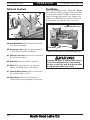
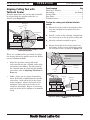
Assembly
With the exception of the handwheel handles, the
lathe is shipped fully assembled.
To install the handwheel handles, thread the
large handle into the carriage handwheel and the
small handle into the cross slide handwheel, as
shown in Figure 13.
Handwheel
Handles
Figure 13. Handwheel handles installed.
To level the machine, use a precision level to
make sure the bedways are level from side-to-
side and from front-to-back.
— If using the included leveling pads
(Figure 11), place them under the six
leveling stud locations, then adjust the
studs to level the lathe.
— If using mounting hardware that does not
allow for adjustment, level the lathe by
placing metal shims between the lathe
base and the floor before bolting down.
Figure 11. Leveling pads and screws.
Pads
Studs
Lubricating Lathe
GEARBOXES MUST
BE FILLED WITH OIL!
NO OIL SHIPPED WITH
MACHINE!
Refer to the Lubrication
Section in this Manual
for Recommended
Oil Type.
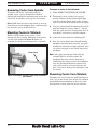
Bolting to Concrete Floors
Lag Screw
and Anchor
Anchor
Stud
Lag screws and anchors, or anchor studs
(below), are two popular methods for securing
machinery to a concrete floor. We suggest you
research the many options and methods for
securing your machine and choose the best one
for your specific application.
Figure 12. Common types of fasteners for bolting
machinery to concrete floors.
Most electrical codes require that machines
connected to the power source by fixed
conduit MUST be secured to the floor.
The headstock, gearbox, and apron oil reservoirs
must have the proper amount of oil in them
before the lathe can be operated for the first
time.
Running the lathe without oil in a gearbox is
considered unwarrantable abuse, which may
result in damage to the bearings and gears. Refer
to the Lubrication section, beginning on Page
56, for details on how to check and add oil.

For Machines Mfg. Since 7/09 EVS Toolroom Lathes
-15-
PREPARATION
In addition to the gearboxes, we also recommend
that you lubricate all other points on the
machine at this time. This can be accomplished
by following the maintenance schedule on Page
54.
Note: If your lathe was shipped with oil in the
gearboxes, do not change that oil until after the
break-in period.
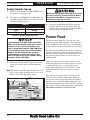
Power Connection
Electrocution or fire
may occur if machine is
ungrounded, incorrectly
connected to power, or
connected to an undersized
circuit. Use a qualified
electrician to ensure a safe
power connection.
Once all preparation steps previously described
in this manual have been completed, the
machine can be connected to the power source.
In order to be connected to the power source, a
circuit must be installed/prepared that meets
the requirements of the lathe, and a power
connection method must be established for that
circuit. The following lists show the minimum
requirements for each model, and instructions
follow for each connection method.
Note About Power Cords: Using an incorrectly
sized cord causes electrical components on
the machine and the cord to become very hot,
which will greatly decrease the life of electrical
components or result in fire. For best results,
use the shortest length of cord possible for your
machine, and never use a smaller cord gauge
than the specified minimum.
This machine is equipped with a frequency
drive that contains sensitive electronics,
which can be damaged by a phase converter.
DO NOT use a phase converter to power this
machine. Doing so will void the warranty.
Adding Cutting Fluid
Add the cutting fluid of your choice now. For
detailed instructions on where the cutting fluid
tank is located and how to add fluid, refer to
Cutting Fluid System on Page 62.
SB1012 (220V 3-Phase)
Full Load Amp Draw ............................ 15.7 Amps
Phase ..........................................................3-Phase
Frequency ...................................................... 60 Hz
Minimum Circuit Size ............................. 20 Amps
Recommended Plug/Receptacle ......NEMA L15-20
Minimum Cord Size .......... 12 AWG, 4-Wire, 300V
Maximum Cord Length ................................. 50 ft.
SB1014, SB1037 (220V 3-Phase)
Full Load Amp Draw ............................ 21.7 Amps
Phase ..........................................................3-Phase
Frequency ...................................................... 60 Hz
Minimum Circuit Size ............................. 30 Amps
Recommended Plug/Receptacle ......NEMA L15-30
Minimum Cord Size ............ 8 AWG, 4-Wire, 300V
Maximum Cord Length ................................. 50 ft.
SB1013 (440V 3-Phase)
Full Load Amp Draw ............................ 7.75 Amps
Phase ..........................................................3-Phase
Frequency ...................................................... 60 Hz
Minimum Circuit Size ............................. 15 Amps
Recommended Power Connection ........ Hardwire*
SB1015, SB1038 (440V 3-Phase)
Full Load Amp Draw .......................... 10.75 Amps
Phase ..........................................................3-Phase
Frequency ...................................................... 60 Hz
Minimum Circuit Size ............................. 15 Amps
Recommended Power Connection ........ Hardwire*
* Hardwire setups must include a locking
disconnect switch between the power source and
the lathe. Refer to Page 16 for more details.

-16 -
For Machines Mfg. Since 7/09
EVS Toolroom Lathes
PREPARATION
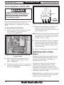
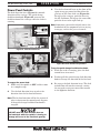
Connecting Power Cord to Lathe
Electrocution or death will occur if you
attempt this procedure with the power cord
connected to the power source. The cord
must be disconnected from power before
performing this procedure.
These instructions are for setups where the lathe
will be connected to the power source with a
power cord and plug, as opposed to a hardwire
setup.
To connect power cord to the lathe:
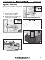
1. Unlock and open the main electrical cabinet
door, and install a strain relief in the
location shown in Figure 14.
Figure 14. Location to connect power inside main
electrical cabinet.
Incoming
Power
Strain
Relief
Main
Power
Switch
4. Make sure the cord/wires have loose slack
between the strain relief and terminal
connections, then tighten the strain relief to
secure the power cord.
Note: The strain relief must be tightened against
the outermost jacket of the cord. Avoid over-
tightening the strain relief or it may crush
the cord and cause a short.
5. Test the strain relief to ensure it is properly
tightened by pulling the cord from outside
the box with light-to-moderate force. When
the strain relief is properly tightened, the
cord will not slide.
6. Close and lock the main electrical box door.
2. Thread the power cord through the strain
relief, and up to the main power switch
shown in Figure 14.
3. Connect the incoming L1, L2, L3 and ground
wires to the main power switch terminals, as
illustrated in Figure 15.
To Power Source
L3
L3
L1
L1
L3
L2
L1
Gn
G
G
G
G
G
G
G
G
G
G
G
G
G
n
t
Wt
W
t
Rd
Rd
Ground
1
1
1
2
3
3
3
5
5
5
6
4
MASTER
POWER SWITCH
L2
L2
Bk
B
Figure 15. Power connection at main power switch.
Hardwire setups require power supply lines to
be enclosed inside of conduit, which is securely
mounted and constructed in adherence to
applicable electrical codes.
A hardwire setup for this machine must be
equipped with a locking disconnect switch
as a means to disconnect the power during
adjustments or maintenance, which is a typical
requirement for lock-out/tag-out safety programs
(commonly required by OSHA).
Figure 16 shows a simple diagram of a hardwire
setup with a locking disconnect switch between
the power source and the machine.
Power
Connection
Terminals
Hardwiring Lathe to Power
Source

For Machines Mfg. Since 7/09 EVS Toolroom Lathes
-17-
PREPARATION
Correcting Out-of-Phase Wiring
This sub-section is only provided for
troubleshooting. If you discover during the test
run that the lathe will not operate, or that the
spindle runs backwards, the lathe may be wired
out of phase. Without the proper test equipment
to determine the phase of power source legs,
wiring machinery to 3-phase power may require
trial-and-error. Correcting this is simply a
matter of reversing the positions where two of
the incoming power source wires are connected.
To correct wiring that is out of phase:
1. Push the stop button, turn the main power
switch to OFF, and disconnect the machine
from power (or shut OFF and lock out the
power source if hardwired).
2. Open the electrical box and disconnect the
L1 and L2 wires shown in Figure 15 on the
"To Power Source" side of the switch.
3. Connect the L1 wire to the terminal where
the L2 wire was connected originally.
4. Connect the L2 wire to the terminal where
the L1 wire was connected originally.
5. Close and latch the electrical box, and
reconnect the machine to the power source.
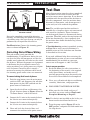
Test Run
After all preparation steps have been completed,
the machine and its safety features must be
tested to ensure correct operation. If you discover
a problem with the operation of the machine or
its safety components, shut the machine down,
disconnect it from power, and do not operate it
again until you have resolved the problem.
Note: The variable speed on this machine is
controlled by a frequency drive unit constructed
with sensitive electronics. These electronics
can be damaged if power is disconnected during
operation. Therefore, unless the stop button and
brake lose functionality, always properly shut
the machine down before disconnecting it from
the power source.
A Troubleshooting section is provided, starting
on Page 74, to assist you with solutions if a
problem occurs or if the lathe does not function
as described in this section.
If you need additional help after reviewing the
troubleshooting section, or you are not confident
troubleshooting the machine on your own,
contact our tech support at (360) 734-1540.
To test run your machine:
1. Read and follow the safety instructions at
the beginning of the manual, take required
safety precautions, and make sure all
previous preparation steps discussed in this
manual have been followed and completed.
2. Clear away all tools and objects used during
assembly, lubrication, and preparation.
3. DISCONNECT LATHE FROM POWER!
4. Make sure that the chuck and jaws, if
installed, are secure (refer to Chuck and
Faceplate Mounting on Page 27).
Note: If a chuck is not installed on the lathe, you
do not need to install one for this test.
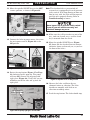
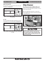
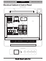
5. Turn the pump switch (Figure 17) to the
OFF position, and point the fluid nozzle into
the chip drawer.
Due to the complexity required for planning,
bending, and installing the conduit necessary for
a hardwire setup, this type of setup can only be
performed by an experienced electrician.
For Electrician: Connect the incoming power
wires as shown in Figure 15.
Power Source
Locking
Disconnect Switch
Machine
Conduit Conduit
Figure 16. Typical hardwire setup with a locking
disconnect switch.

-18-
For Machines Mfg. Since 7/09
EVS Toolroom Lathes
PREPARATION
9. Move the feed direction forward/reverse lever
to the middle (neutral) position, as shown in
Figure 20.
Figure 20. Feed direction forward/reverse lever in the
neutral position.
10. Disengage the half nut lever, put the feed
control lever in neutral, and make sure the
carriage lock bolt is loose (see Figure 6).
This step will allow the carriage to move
freely when the handwheel is rotated and
make sure that the carriage will not move
when the lathe is started.
FORWARD
REVERSE
NEUTRAL
Figure 17. Control panel-test run.
Stop Button
Pump Switch
6. Turn the spindle speed dial (Figure 18) all
the way counterclockwise (lowest speed) to
avoid possibility of a high-speed start.
Figure 19. Gearbox range lever in middle position.
LOW
Neutral
HIGH
Figure 18. Spindle speed controls.
Low
20-400 RPM
High
400-2500 RPM
Spindle Speed Dial
7. Move the spindle speed range lever (Figure
18) to the left so the headstock is set in the
low range (20-400 RPM). (You may need to
slightly rotate the chuck by hand to engage
the lever.)
8. Move the gearbox range lever to the middle
(neutral) position, as shown in Figure 19.
Figure 21. Controls used to disengage carriage so that
it will move freely when the handwheel is turned.
Engaged
HALF NUT
LEVER
Disengaged
Cross Slide
Neutral
FEED CONTROL
LEVER
Carriage
Feed Control Lever
Half Nut Lever
Carriage Lock Bolt
Page is loading ...
Page is loading ...
Page is loading ...
Page is loading ...
Page is loading ...
Page is loading ...
Page is loading ...
Page is loading ...
Page is loading ...
Page is loading ...
Page is loading ...
Page is loading ...
Page is loading ...
Page is loading ...
Page is loading ...
Page is loading ...
Page is loading ...
Page is loading ...
Page is loading ...
Page is loading ...
Page is loading ...
Page is loading ...
Page is loading ...
Page is loading ...
Page is loading ...
Page is loading ...
Page is loading ...
Page is loading ...
Page is loading ...
Page is loading ...
Page is loading ...
Page is loading ...
Page is loading ...
Page is loading ...
Page is loading ...
Page is loading ...
Page is loading ...
Page is loading ...
Page is loading ...
Page is loading ...
Page is loading ...
Page is loading ...
Page is loading ...
Page is loading ...
Page is loading ...
Page is loading ...
Page is loading ...
Page is loading ...
Page is loading ...
Page is loading ...
Page is loading ...
Page is loading ...
Page is loading ...
Page is loading ...
Page is loading ...
Page is loading ...
Page is loading ...
Page is loading ...
Page is loading ...
Page is loading ...
Page is loading ...
Page is loading ...
Page is loading ...
Page is loading ...
Page is loading ...
Page is loading ...
Page is loading ...
Page is loading ...
Page is loading ...
Page is loading ...
Page is loading ...
Page is loading ...
Page is loading ...
Page is loading ...
Page is loading ...
Page is loading ...
Page is loading ...
Page is loading ...
Page is loading ...
Page is loading ...
Page is loading ...
Page is loading ...
Page is loading ...
Page is loading ...
Page is loading ...
Page is loading ...
Page is loading ...
Page is loading ...
Page is loading ...
Page is loading ...
Page is loading ...
Page is loading ...
Page is loading ...
Page is loading ...
Page is loading ...
Page is loading ...
Page is loading ...
Page is loading ...
Page is loading ...
Page is loading ...
Page is loading ...
Page is loading ...
Page is loading ...
Page is loading ...
Page is loading ...
Page is loading ...
Page is loading ...
Page is loading ...
Page is loading ...
Page is loading ...
Page is loading ...
Page is loading ...
Page is loading ...
Page is loading ...
Page is loading ...
Page is loading ...
Page is loading ...
Page is loading ...
Page is loading ...
Page is loading ...
Page is loading ...
Page is loading ...
Page is loading ...
Page is loading ...
-
 1
1
-
 2
2
-
 3
3
-
 4
4
-
 5
5
-
 6
6
-
 7
7
-
 8
8
-
 9
9
-
 10
10
-
 11
11
-
 12
12
-
 13
13
-
 14
14
-
 15
15
-
 16
16
-
 17
17
-
 18
18
-
 19
19
-
 20
20
-
 21
21
-
 22
22
-
 23
23
-
 24
24
-
 25
25
-
 26
26
-
 27
27
-
 28
28
-
 29
29
-
 30
30
-
 31
31
-
 32
32
-
 33
33
-
 34
34
-
 35
35
-
 36
36
-
 37
37
-
 38
38
-
 39
39
-
 40
40
-
 41
41
-
 42
42
-
 43
43
-
 44
44
-
 45
45
-
 46
46
-
 47
47
-
 48
48
-
 49
49
-
 50
50
-
 51
51
-
 52
52
-
 53
53
-
 54
54
-
 55
55
-
 56
56
-
 57
57
-
 58
58
-
 59
59
-
 60
60
-
 61
61
-
 62
62
-
 63
63
-
 64
64
-
 65
65
-
 66
66
-
 67
67
-
 68
68
-
 69
69
-
 70
70
-
 71
71
-
 72
72
-
 73
73
-
 74
74
-
 75
75
-
 76
76
-
 77
77
-
 78
78
-
 79
79
-
 80
80
-
 81
81
-
 82
82
-
 83
83
-
 84
84
-
 85
85
-
 86
86
-
 87
87
-
 88
88
-
 89
89
-
 90
90
-
 91
91
-
 92
92
-
 93
93
-
 94
94
-
 95
95
-
 96
96
-
 97
97
-
 98
98
-
 99
99
-
 100
100
-
 101
101
-
 102
102
-
 103
103
-
 104
104
-
 105
105
-
 106
106
-
 107
107
-
 108
108
-
 109
109
-
 110
110
-
 111
111
-
 112
112
-
 113
113
-
 114
114
-
 115
115
-
 116
116
-
 117
117
-
 118
118
-
 119
119
-
 120
120
-
 121
121
-
 122
122
-
 123
123
-
 124
124
-
 125
125
-
 126
126
-
 127
127
-
 128
128
-
 129
129
-
 130
130
-
 131
131
-
 132
132
-
 133
133
-
 134
134
-
 135
135
-
 136
136
-
 137
137
-
 138
138
-
 139
139
-
 140
140
-
 141
141
-
 142
142
-
 143
143
-
 144
144


Ask a question and I''ll find the answer in the document
Finding information in a document is now easier with AI
Related papers
-
 South bend SB1014 Owner's manual
-
 South bend SB1012 Owner's manual
-
 South bend SB1012F Owner's manual
-
 South bend SB1037F Owner's manual
-
 South bend SB1038F Owner's manual
-
 South bend SB1013F Owner's manual
-
South bend SB1014F Owner's manual
-
 South bend SB1015F Owner's manual
-
Grizzly G0554Z User manual
-


