Page is loading ...

Model # 3455
VARIABLE SPEED
7 X 12 IN. METAL LATHE
bit.ly/wenvideo
Your new tool has been engineered and manufactured to WEN’s highest standards for dependability,
ease of operation, and operator safety. When properly cared for, this product will supply you years
of rugged, trouble-free performance. Pay close attention to the rules for safe operation, warnings,
and cautions. If you use your tool properly and for intended purpose, you will enjoy years of safe,
reliable service.
IMPORTANT:
NEED HELP? CONTACT US!
Have product questions? Need technical support?
Please feel free to contact us at:
800-232-1195
WENPRODUCTS.COM
(M-F 8AM-5PM CST)

TABLE OF CONTENTS
Technical Data
2
3
4
6
7
8
9
19
20
22
25
General Safety Rules
Specific Safety Rules For Metal Lathes
Electrical Information
Know Your Lathe
Assembly
Troubleshooting Guide
Exploded View & Parts List
Warranty
TECHNICAL DATA
Model Number:
Motor:
Swing Over Bed:
Distance Between Centers:
Spindle Bore:
Cross Slide Travel:
Compound Slide Travel
Speeds:
Spindle Taper:
Tailstock Taper:
Longitudinal Feed Rate:
Screw Threads:
Weight:
3455
120V, 60Hz, 4A
7 in. (180 mm)
12 in. (300 mm)
.79 in. (20 mm)
2-1/2 in. (65 mm)
2.16 in. (55 mm)
100 to 2500 RPM
MT3
MT2
.1 to .2 mm
15 to 52 TPI in 18 steps
81 lbs.
2
Maintenance
Operation

3
GENERAL SAFETY RULES
Safety is a combination of common sense, staying alert and knowing how your item works. SAVE THESE SAFE-
TY INSTRUCTIONS.
WARNING: To avoid mistakes and serious injury, do not plug in your tool until the following
steps have been read and understood.
1. READ and become familiar with this entire instruction manual. LEARN the tool’s applications, limitations, and
possible hazards.
2. AVOID DANGEROUS CONDITIONS. Do not use power tools in wet or damp areas or expose them to rain.
Keep work areas well lit.
3. DO NOT use power tools in the presence of flammable liquids or gases.
4. ALWAYS keep your work area clean, uncluttered, and well lit. DO NOT work on floor surfaces that are slippery
with sawdust or wax.
5. KEEP BYSTANDERS AT A SAFE DISTANCE from the work area, especially when the tool is operating.
NEVER allow children or pets near the tool.
6. DO NOT FORCE THE TOOL to do a job for which it was not designed.
7. DRESS FOR SAFETY. Do not wear loose clothing, gloves, neckties, or jewelry (rings, watches, etc.) when op-
erating the tool. Inappropriate clothing and items can get caught in moving parts and draw you in. ALWAYS wear
non-slip footwear and tie back long hair.
8. WEAR A FACE MASK OR DUST MASK to fight the dust produced by operation.
WARNING: Dust generated from certain materials can be hazardous to your health. Always oper-
ate the tool in a well-ventilated area and provide for proper dust removal. Use dust collection sys-
tems whenever possible.
9. ALWAYS remove the power cord plug from the electrical outlet when making adjustments, changing parts,
cleaning, or working on the tool.
10. KEEP GUARDS IN PLACE AND IN WORKING ORDER.
11. AVOID ACCIDENTAL START-UPS. Make sure the power switch is in the OFF position before plugging in
the power cord.
12. REMOVE ADJUSTMENT TOOLS. Always make sure all adjustment tools are removed from the tool before
turning it on.
13. NEVER LEAVE A RUNNING TOOL UNATTENDED. Turn the power switch to OFF. Do not leave the
tool until it has come to a complete stop.
14. NEVER STAND ON A TOOL. Serious injury could result if the tool tips or is accidentally hit. DO NOT store
anything above or near the tool.

4
15. DO NOT OVERREACH. Keep proper footing and balance at all times. Wear oil-resistant rubber-soled foot-
wear. Keep the floor clear of oil, scrap, and other debris.
16. MAINTAIN TOOLS PROPERLY. ALWAYS keep tools clean and in good working order. Follow instruc-
tions for lubricating and changing accessories.
17. CHECK FOR DAMAGED PARTS. Check for alignment of moving parts, jamming, breakage, improper
mounting, or any other conditions that may affect the tool’s operation. Any part that is damaged should be properly
repaired or replaced before use.
18. MAKE THE WORKSHOP CHILDPROOF. Use padlocks and master switches and ALWAYS remove start-
er keys.
19. DO NOT operate the tool if you are under the influence of drugs, alcohol, or medication that may affect your
ability to properly use the tool.
20. USE SAFETY GOGGLES AT ALL TIMES that comply with ANSI Z87.1. Normal safety glasses only have
impact resistant lenses and are not designed for safety. Wear a face or dust mask when working in a dusty environ-
ment. Use ear protection such as plugs or muffs during extended periods of operation.
GENERAL SAFETY RULES
SPECIFIC RULES FOR METAL LATHES
1. This lathe is designed and intended for use by properly trained and experienced personnel only. If you are not
familiar with the proper and safe operation of a lathe, do not use it until proper training and knowledge have been
acquired.
2. Always wear eye protection and a face shield/dust mask when using the lathe.
3. Make sure all tools, chisels and accessories are sharp enough for the task at hand before using them. Always use
the right tool at the correct speed and feed rate.
4. Turn off and unplug the machine before doing any cleaning or maintenance. Use a brush to remove chips or
debris. Never use your hands to remove excess material and debris.
5. Check the workpiece carefully for inconsistencies or obstructions. These types of blemishes may cause a safety
risk during turning.
6. Rotate the workpiece by hand to check clearance before turning the machine on.
7. Select the appropriate speed for the task at hand. Start at a low speed and allow the lathe to ramp up to the operat-
ing speed before engaging any chisels, tools or other carving accessories.
8. Never stop a rotating workpiece with your hand.
9. When turning between centers, make sure the headstock and tailstock are tight and snug against the workpiece.
10. Always use a brush or rag to clear away chips from turning. Using your hand can cause serious injury.

11. Always remove the key from the chuck jaws before operation.
12. Always wear a full face mask. If a tool or workpiece breaks off, it can create a hazard to users and onlookers.
13. Always use the right cutting tool. An improper tool could break or cause unwanted strain on the machine.
14. Never attempt to stop the lathe with your hand. You will lose your hand.
15. Always use the proper feed rate for your workpiece. An overly fast feed rate can damage the lathe or the work-
piece.
16. Secure the workpiece properly, make sure the chuck is tight and secure on the workpiece before beginning to
turn. A loose workpiece can shoot out and severely injure you or anyone around.
17. Use a tailstock to support long work stock. Anything more than 2.5 times as long as it is thick needs the tailstock
to support it.
18. Never operate the lathe with damaged parts
19. Never turn a workpiece at RPMs that are too high for the work material. This can cause the cutting tool to break
and launch off, injuring you or a bystander.
20. Never reverse motor direction while the machine is running
21. Never change the lead screw feed direction while the machine is running
22. Always ensure proper clearance between the workpiece and the cross slide, compound slide, and tool post.
23. Always disengage automatic feed after a cutting pass, even if it is the final cut. You can forget and hurt yourself
upon next use.
24. Always tie up long hair. Do not wear any loose/hanging clothing. Even aprons can be hazards when improperly
secured.
SPECIFIC RULES FOR LATHES

ELECTRICAL INFORMATION
GROUNDING INSTRUCTIONS
IN THE EVENT OF A MALFUNCTION OR BREAKDOWN, grounding provides the path of least resistance
for an electric current and reduces the risk of electric shock. This tool is equipped with an electric cord that has an
equipment grounding conductor and a grounding plug. The plug MUST be plugged into a matching outlet that is
properly installed and grounded in accordance with ALL local codes and ordinances.
DO NOT MODIFY THE PLUG PROVIDED. If it will not fit the outlet, have the proper outlet installed by a
licensed electrician.
IMPROPER CONNECTION of the equipment grounding conductor can result in electric shock. The conduc-
tor with the green insulation (with or without yellow stripes) is the equipment grounding conductor. If repair or
replacement of the electric cord or plug is necessary, DO NOT connect the equipment grounding conductor to a
live terminal.
CHECK with a licensed electrician or service personnel if you do not com-
pletely understand the grounding instructions or whether the tool is properly
grounded.
USE ONLY THREE-WIRE EXTENSION CORDS that have three-pronged
plugs and outlets that accept the tool’s plug as shown. Repair or replace a dam-
aged or worn cord immediately.
CAUTION: In all cases, make certain the outlet in question is properly grounded. If you are not sure, have a li-
censed electrician check the outlet.
WARNING: This tool is for indoor use only. Do not expose to rain or use in damp locations. This tool
must be grounded while in use to protect the operator from electric shock.
GUIDELINES FOR EXTENSION CORDS
Make sure your extension cord is in good condition. When using an extension cord, be sure to use one heavy
enough to carry the current your product will draw. An undersized cord will cause a drop in line voltage resulting
in loss of power and overheating. The table below shows the correct size to be used according to cord length and
nameplate ampere rating. When in doubt, use a heavier cord. The smaller the gauge number, the heavier the cord.
Make sure your extension cord is properly wired and in good condition. Always replace a damaged extension cord
or have it repaired by a qualified person before using it. Protect your extension cords from sharp objects, excessive
heat and damp/wet areas.
Use a separate electrical circuit for your tools. This circuit must not be less than a #12 wire and should be protected
with a 15 A time-delayed fuse. Before connecting the motor to the power line, make sure the switch is in the OFF
position and the electric current is rated the same as the current stamped on the motor nameplate. Running at a
lower voltage will damage the motor.
AMPERAGE
REQUIRED GAUGE FOR EXTENSION CORDS
25 ft. 50 ft. 100 ft. 150 ft.
4A 18 gauge 16 gauge 16 gauge 14 gauge
6

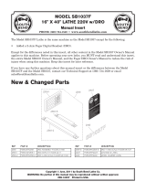
A - Running Gear Cover
B - Lathe Control Panel
C - Head Stock
D - Spindle
E - 3-Jaw Chuck
F - Tool Post Lock
G - Cross Slide Handle
H - Compound Slide
I - Quill
J - Tailstock Quill Lock
K - Tailstock Hand Wheel
L - Tailstock
M - Tailstock Lock Nut
N - Compound Slide Hand Wheel
O - Automatic Feed Lever
P - Cross Slide
Q - Manual (Carriage) Feed Handle
R - Tool Post
NOT PICTURED (ref. page 8 for locations):
High/Low Speed Range Lever (behind headstock)
Forward/Neutral/Reverse Lever (behind headstock)
7
AMPERAGE
REQUIRED GAUGE FOR EXTENSION CORDS
25 ft. 50 ft. 100 ft. 150 ft.
4A 18 gauge 16 gauge 16 gauge 14 gauge
KNOW YOUR LATHE
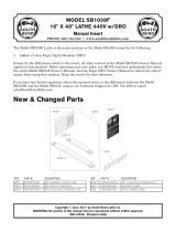
LATHE CONTROL PANEL
Before operating your lathe, become familiar with the controls.
Figure A below depicts the control panel.
A. VARIABLE SPEED CONTROLLER: Allows the adjust-
ment of the lathe’s speed from 0 to 2500 RPM.
B. EMERGENCY SHUTOFF: Stops power to the unit when
pressed during operation.
C. SPINDLE DIRECTION SELECTOR: Allows the user to
select the direction of the spindle between clockwise (forward),
neutral (O), and counterclockwise (reverse).
D
Fig. A - Lathe Control
E
H
F
G
A
Q
N
I
L
O
P
R
C
J
K
M
B
DO NOT CHANGE THE SPINDLE DIRECTION WHILE THE UNIT IS RUNNING! IT WILL
DAMAGE THE LATHE!
D. FUSE CAP: Contains the fuse that protects the unit from circuit overloads.

8
TO ASSEMBLE
Attach the plastic handles to the rims of the manual feed and tailstock feed handwheels respectively. Ensure the
nuts are tight and the handles spin freely about the bolts without excessive end play.
The carriage, cross-slide and compound slide adjustments are all factory set to ensure smooth movement in both
directions. However the adjustments may have been misalligned during transportation. This will be indiciated by
stiff or erratic movement. Refer to “Settings and Adjustments” for methods of adjusting.
All hex keys and spanners necessary to carry out various adjustments are supplied together with a chuck key for
the 3-jaw chuck and a spare fuse. The fuse holder is located on the main control panel.
The four rubber feet are attached to the underside of the bed, using the four M6 pan head screws in the tapped
holes provided. These screws are also used to secure the hip tray. We strongly recommend that to provide maxi-
mum stability and safety, users should secure the lathe to a firm foundation as described under “Mounting the
Lathe” below.
UNPACKING
Carefully unpack the lathe and all its parts. Compare against the list below. Do not discard the carton or any
packaging until the lathe is completely assembled.
WARNING: If any part is missing or damaged, do not plug in the tool until the missing or damaged
part is replaced.
Lathe
Rubber Feet (4)
M6 Pan Head Screws (4)
Hex Keys (4)
Chuck Key
Plastic Oil Container
Spare Fuse
Plastic Handles w/ Nuts and Bolts
No. 2 Morse Taper Center (Tailstock)
External Jaws for 3-Jaw Chuck (3)
8 x 10 mm Spanner
14 x 17 mm Spanner
Gear Set
A
B
Fig. A2
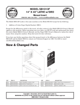
BEHIND HEADSTOCK (Fig. A2)
A) HIGH/LOW RANGE LEVER: Allows the
user to shift the spindle speed range from HIGH
(0-2500 RPM) to LOW (0-1100 RPM).
DO NOT SHIFT FROM HIGH TO LOW
WHILE THE LATHE IS RUNNING!
B) LEAD SCREW DIRECTION LEVER:
Change the direction of the lead screw rotation
between forward, reverse, and neutral.
DO NOT CHANGE DIRECTION OF THE
LEAD SCREW WHILE THE LATHE IS
RUNNING!
ASSEMBLY
KNOW YOUR LATHE

9
OPERATION
MOUNTING THE LATHE (FIG. B)
The lathe should be mounted on a strong, heavy
workbench. Take the necessary precautions when
moving the lathe. Assistance may be required.
Bolt the machine firmly to the workbench us-
ing the tapped holes. To do this remove the M6
screws securing the rubber feet in place. Drill four
M6 clearance holes in the worktop and find wash-
ers and M6 screws long enough to securely hold
the unit in place.
HEADSTOCK
The headstock contains the motor, pulleys and the drive belt that turn the spindle used to create your workpiece.
The spindle has a MT3 taper for use in conjunction with a face plate or turning clamp. The spindle has a flange
attached with 6 holes arranged to mount different fixtures, such as chuck jaws and face plates. The speed of the
spindle is adjusted via the Variable Speed Controller on the control panel. The speed ranges can be swapped
between two ranges with the lever on the back of the headstock. Do not change the speed range during operation.
CARRIAGE
The carriage is the portion of the lathe that moves the Cross Slide and Compound Slide across the bed. It can be
manually fed, or driven with the lead screw by using a drive nut with the lead screw Direction Lever.
CROSS SLIDE
The cross slide is used to move the tool post and cutting tool across the bed, perpendicular to the lead screw and
the center axis of the spindle. The cross slide is adjusted via a handwheel with precision tick marks, each indi-
cating 0.001”. This scale will rotate with the handwheel when it is turned to feed the cross slide back and forth.
Before beginning a turning, perform the following steps to adjust and zero your cross slide:
1. Turn the handwheel counterclockwise to back the cross slide 0.015” away from your starting point, then slowly
turn the handle clockwise until the cross slide returns to the starting position. This removes any play in the slide to
help make the scale more accurate.
2. Now hold the handwheel steady and with your other hand rotate the scale so the “0” lines up with the “0.000”
mark on the cross slide. From this point the slide will remain accurate as long as you only move it forward.
3. Any time you back feed the slide away from your workpiece you will have to repeat steps 1 and 2 before mov-
ing the cross slide forward again for the next cut.
Fig. B

1010
OPERATION
CARRIAGE FEED
The feed of the carriage along the axis of the spindle can be done manually by you, or automatically by the lead
screw and gear train.
To manually feed the carriage:
1. Use the handwheel on the carriage to move it along the bed. Turning it clockwise will move it away from the
spindle and turning it counter-clockwise will move it towards the spindle.
2. To set the handwheel scale for the carriage feed, move the carriage to your starting point. Then back it up
0.015” from the starting point.
3. From there slowly feed the carriage back to the starting point.
4. While holding the handwheel in place, slowly turn the scale so that the “0” and the “0.000” marks line up on
the scale.
5. Repeat this process for each pass of the carriage
To automatically feed the carriage:
1. Set the carriage to your starting point and zero out the scale by following steps 2-5 above in the “to manually
feed the carriage” section
2. While the unit is still turned off, set the Lead Screw Direction Lever to FORWARD, and set the Spindle Di-
rection Selector to Forward.
3. Turn the lathe on and set it to the necessary RPM using the Variable Speed Controller
4. Push the feed lever down to engage the lead screw the automatic feed function.
5. Once the pass of the tool is finished pull back the lever to disengage the lead screw and the automatic feed.
Fig. C
COMPOUND SLIDE
The compound slide works similarly to the cross slide with a
small handwheel and a scale with tick marks every 0.001”. The
compound slide can be fed back and forth with this handwheel,
similar to the cross slide. In addition it can also be rotated to an
angle of your choice and fed back and forth along this angle. Fol-
low these steps to adjust the compound slide:
1. Loosen the two bolts shown in Fig. C with an allen key
2. Rotate the compound slide to the desired angle and retighten
the bolts to lock it in place.
3. Turn the handwheel until your slide is at its starting point.
Then back the slide 0.015” from the starting point.
4. Slowly turn the handwheel to feed the slide forward until it returns to the starting point.
5. Hold the handwheel in place and rotate the scale so the “0” and “0.000” lines match and the scale is properly
zeroed.
6. Repeat steps 3-5 for each cut and each time you adjust the slide in order to get the most accurate cuts.

11
ADJUSTMENTS
TAILSTOCK
The tailstock is located on the bed opposite of the headstock. It can be moved along the bed by loosening the 17
mm nut (Fig. D - Item E) and pushing the tailstock to the desired position. When it is in the desired spot, tighten
the 17 mm nut to lock it in place. The tailstock is equipped with an MT2 taper to use with appropriate tools, like
the included center, or a properly tapered drill chuck or drill bit. The tailstock arrives properly aligned to the
headstock from the factory. This allows the use of dead or live centers, as well as on center drilling to be per-
formed on the workpiece. If you need to create a taper to the workpiece it is necessary to offset the tailstock (see
“Offsetting your tailstock” section for more info).
F
G
A
B
C
D
E
TAILSTOCK COMPONENTS (FIG. D):
A. Tailstock Handwheel: Feeds the quill in and
out of the tailstock into the workpiece. Use to
push a center into the workpiece to hold it level
horizontally, or to feed a drill into the workpiece
to create a hole.
B. Offset Setscrew: Locks the tailstock position to
allow for offset alignment
C. Offset Cap Screw: Allows tailstock alignment
to be adjusted to right or left of center (underside
of tailstock)
D. Offset Gib Screw: Adjusts the amount of play
in the tailstock quill (underside of tailstock)
E. Tailstock Lock Nut: Secures the tailstock in
place on the bed
F. Quill: Holds MT2 tapered tools in the tailstock
G. Quill Lock: Secures the quill in place
USING A CENTER WITH THE TAILSTOCK
If you are turning a workpiece with stock that hangs more than 2.5 times its diameter beyond the headstock it is
necessary to support the other end with a center and the tailstock. For projects that allow low rpm turning, a dead
center is okay. If higher RPMs are necessary, it is recommended to invest in a live center. To install:
1. Check the center and tailstock quill for any dirt, dust, debris or oil. Wipe both down, as excessive oil or dirt will
not allow the tapers to interlock.
2. Turn the tailstock handwheel until the quill protrudes approximately 1 inch from the tailstock
3. Slide the center into the quill until it is snug, the tapers will keep the center in place. Keep the quill extended
between 0 and 1.5 on the quill scale to keep it secure.
4. To remove the center use the tailstock handwheel to retract the quill into the tailstock completely. This forces
the center out of the quill. Hold the head of the center with your hand to catch it as the center becomes loose.
Fig. D

12
OPERATION
OFFSETTING YOUR TAILSTOCK
WARNING: The tailstock comes from the factory properly aligned with the headstock. Making any adjustments
or offsets will require aligning of the tailstock.
The tailstock can also be used in an offset position to help turn tapers on a work piece. Adjusting the tailstock into
an offset position requires removing the tailstock from the bed and adjusting the offset screw on the bottom of the
tailstock. To properly offset the tailstock follow these steps:
1. Use a 17mm wrench or socket to loosen the lock nut that holds the tailstock in place. Then slide the tailstock
off the bed.
2. Loosen the offset setscrew on the back of the tailstock, below the handwheel.
3. Loosen the offset cap screw on the bottom of the tailstock. Only loosen it enough so the tailstock can slide.
4. Slide the tailstock back onto the bed and adjust it to the desired offset.
5. Tighten the offset setscrew to hold the tailstock at the proper offset position.
6. Slowly and carefully slide the tailstock off the bed and tighten the offset cap screw on the bottom.
7. Slide the tailstock back into the bed, lock it in to the desired position and check your tolerances to makes sure
it is in the desired offset.
8. Repeat the previous steps in order to adjust the offset to the exact position necessary for your turning work
piece.
TOOL POST
The tool post is used to hold your cutting tools and run the cutting edge along the workpiece you are turning. The
tool post can hold four tools at a time and has 4 preset stops at 90 degree intervals. It can also be set at any angle
in between these four presets. To install a cutting tool into the tool post follow these steps:
1. Determine which cutting tool will create the desired cut profile.
2. Loosen the screws in the top of the tool post on the edge you will place the cutting tool. Make sure the tool will
be secured by a minimum of two of these screws.
3. Place the tool under the screws and loosely tighten them
4. Align the tip of the tool with the centerline of the workpiece. If the workpiece centerline is higher, place shims
under the tool to raise its height. This machine uses 5/16” tools. To determine if the tool tip is even with the cen-
terline check the tool tip against the tip of the center in the tailstock. If the two tips are even or the tool tip is below
the center tip, the tool is the proper height. If the tool tip is higher than the center tip, the tool is the improper size
for this lathe.

GEAR TRAIN
WARNING: Before making any of these adjustments, turn off and unplug the lathe from its power source.
The gear train is located on the headstock opposite the spindle. The drive gear is located under a cover secured
by two hex screws. The gear train is used to drive the lead screw that allows the Auto Feed Function to operate.
As the gear train turns, it turns the Lead screw which moves the saddle across the bed of the lathe. The direction
13
OPERATION
THREADS PER INCH (TPI)
TPI
Gear Size (mm)
A B C D
12 40 65 / 30
13 40 65 60 30
14 40 65 / 35
16 40 65 / 40
18 40 65 / 45
19 40 50 60 57
20 40 65 / 50
22 40 65 / 55
24 40 65 / 60
26 40 60 / 65
28 20 65 / 35
32 20 65 / 40
36 20 65 / 45
38 20 50 60 57
40 20 65 / 50
44 20 65 / 55
48 20 65 / 60
52 20 60 / 65
METRIC THREAD PITCH
CHART
mm /
pitch
Gear Size (mm)
A B C D
0.4 20 50 40 60
0.5 20 50 / 60
0.6 40 50 30 60
0.7 40 50 35 60
0.8 40 50 40 60
1.0 20 60 / 30
1.25 50 40 / 60
1.5 40 60 / 40
1.75 35 60 / 30
2.0 40 60 / 30
is set using the Lead screw Direction Lever. Adjusting it to forward will
send the saddle towards the headstock. Reverse sends it away, and neu-
tral disengages the lead screw so the saddle can be manually fed.
The feed rate of the lead screw can be set by changing the gears in the
gear train (Fig. E). Switching the diameter of the gears and the order
of the gears will change the torque and speed of lead screw, allowing
for different threads to be turned with the lathe. The Threading Chart
to the right shows the gear arrangements to use to achieve different
threads per inch (TPI) or metric pitches when using the lead screw.
To change the gears to match up with these gear charts follow these
steps:
1. Remove the gear cover to expose the drive gear.
2. Loosen the adjustment nut at the bottom of the gear train to dis-
engage the gears from one another. Remove the necessary gears and
replace them with the appropriate gears. That is, the gears that have the
proper number of teeth in the positions called for (30, 40, 60, and 65
teeth). Note that sometime configurations do not require gears in every
position, and some require you to move the bushings from one shaft to
another for gears to properly fit in place.
3. Position the gears so their teeth will mesh together properly once the
adjuster is tightened.
ADJUSTER
A
B
C
D
Fig. E

OPERATION
14
TO CREATE A NORMAL TURNING
Before starting a turning, always plan your work ahead of time. Create a drawing or plan with all of the dimensions
you desire for the workpiece. Make sure to have all the measuring tools you will need to double and triple check
your cuts.
Place the work into the chuck or attach to the faceplate. If necessary, use the tailstock center to support the oppo-
site end. If the tailstock is not needed, it can be removed completely by taking off the nut and sliding the tailstock
off the bed.
After you have the work planned out, select the necessary cutting tools for the feature you wish to create and
mount it to the tool post. Make sure the tool tip is aligned with the center line of the workpiece, or slightly below
(double check the tool mounting procedure in the “Tool Post” section).
Mark the end point for the cut on the work piece using a scriber. Line up the cutting tool with the end point and
feed in the cross slide until it just touches the surface of the workpiece. Then turn the spindle by hand to make
sure there is no interference between the carriage, cross slide, tool post, cutting tool, or chuck. It may be necessary
to adjust the compound slide or the workpiece in the chuck to get the proper amount of clearance.
When you have assured there is adequate clearance, back the cross slide away from the work piece and move the
carriage away from the head stock. Next zero out the cross-slide:
1. Feed the cross slide and the cutting tool to the starting position of the cut.
2. Back the cross slide 0.015” away from the work piece.
3. Slowly feed the cross slide back to the starting point.
4. Hold the handwheel to move the cross slide in place with one hand, and turn the dial of the gauge to make the
0 and the 0.000 marks line up. The cross slide and cutting tool are now zeroed out.
5. If you have to back feed the cross slide at all repeat steps 1 through 4.
NOTE: Before each pass of the cutting tool, it is recommended to add oil to the work piece to reduce heat and
friction. Make sure to periodically add oil to the work piece as needed while turning.
USING MANUAL FEEDING
Double check the following before you begin turning:
1. The Auto Feed Lever is in the UP position to disengage the leadscrew
2. The Auto Feed Direction Lever is in NEUTRAL
3. You are in the appropriate speed selection of HIGH/LOW for the material you are turning
To know the proper RPM will take some experience, harder metals should use a slower RPM while softer can use
a little faster RPM. If you are unsure it is better to go slower than risk damage to the work, the cutting tool or the
lathe by using too high of an RPM.
(CONTINUED ON NEXT PAGE)

OPERATION
15
(CONTINUED FROM LAST PAGE)
Once you are ready to begin, switch the machine ON and set the RPM to your desired level. Slowly feed the cut-
ting tool into the work piece using the carriage handwheel. Slowly feed the cutting tool across the work piece until
you reach the marked end point. Retract the cross slide and cutting tool at this point one or two full revolutions.
Return the carriage to the starting point, and then feed the tool back in the same number of revolutions plus a
small additional feed rate in. Repeat this process until you have the desired amount of material cut away.
USING AUTOMATIC FEED
Once you have the cross slide set in position double check the following:
1. The Auto Feed Direction Lever is set to FORWARD.
2. The auto feed lever is disengaged with the lead screw.
3. You are in the appropriate speed selection range of HIGH/LOW.
4. The gear train is in the proper configuration, as this determines the feed rate of the lead screw. The factory set-
ting is okay for normal turning, but if you have been cutting screw threads you will need to reset the gear train to
the proper configuration.
To perform the cut with the automatic feed:
1. Position the cutting tool past the end of the work piece away from the tail stock. Make sure the tool is set to the
proper cutting depth. Always do shallow cuts, as cutting too deep too fast will damage the work piece, your cutting
tool, and your lathe.
2. Double check that all the feed levers are in the proper direction.
3. Turn the unit on, set the spindle speed to the desired rate. Push the autofeed lever down to engage the nut with
the lead screw.
4. Watch your cutting tool. When it reaches the end, quickly press UP on the auto feed lever and make sure it
stays disengaged from the lead screw.
5. Retract the cutting tool one or two turns using the cross slide handwheel. Feed the carriage back to the starting
point, and feed the tool back in one or two turns plus the additional cutting depth.
6. When ready for the next pass, engage the auto feed lever and repeat the previous steps until you have removed
the desired amount of material.

16
OPERATION
BEVEL CUTTING
In order to perform a bevel cut, it is necessary to use the compound slide as well as the cross slide. To align the
compound slide for a bevel cut, align it to the proper angle following the procedure in the “Compound Slide” sec-
tion.
Once the compound slide is aligned to the proper angle, follow these steps to create the bevel:
1. Mark your end point of the bevel if necessary using the methods for a normal turning.
2. Set and zero out the cross slide to the proper starting point.
3. Turn the lathe on and set the spindle to the appropriate RPM.
4. Use the handwheel on the compound slide to feed the cutting tool along the end of the workpiece. This will
create the bevel cut at the angle you set it to.
5. Back off the cutting tool 2 turns and reset the compound slide to the starting point and feed the cutting tool
back in to the cutting depth.
6. Repeat until your bevel is the desired length and position.
TO CUT THREADS
1. Adjust the compound slide so the tool is at the appropriate angle for the desired
thread.
2. Place the tool tip so that it is centered vertically centered and perpendicular to the
workpiece.
3. Engage the thread dial with the lead screw.
4. Use the gear ratio charts (to the left) to determine the proper gear ratio and install the
proper gears.
5. Turn the lathe on and set the RPM using the Variable Speed Controller. Make sure
the lead screw is feeding in the proper direction by engaging the feed lever. When you
are sure it is going in the right direction disengage the feed lever and turn off the lathe.
6. Read the settings off the thread dial chart to get the proper setting for the thread dial.
Make sure the thread dial always engages the half nut on the same mark for every pass
of the cutting tool. If you don’t do this you may cut off threads created in your previous
cut.
THREAD DIAL
TPI SCALE
12 1, 3, 5, 7
13 1
14 1 or 5
16 1 - 8
18 1 or 5
19 1
20 1, 3, 5, 7
22 1 or 5
24 1 - 8
26 1 or 5
28 1, 3, 5, 7
32 1 - 8
36 1, 3, 5, 7
38 1 or 5
40 1 - 8
44 1, 3, 5, 7
48 1 - 8
52 1, 3, 5, 7

17
OPERATION
CHANGING THE JAWS IN YOUR CHUCK (FIG. F)
1. Make sure your lathe is turned off and unplugged.
2. Turn the chuck key counterclockwise until all of the jaws come out
of the chuck.
3. Clean out each slot in the chuck making sure all dirt and debris are
removed.
4. Each jaw has a number or letter (1, 2, 3 or A, B, C) that corresponds
to a number in the slot.
5. Take Jaw #1 and insert the chuck key into the chuck. Turn the key
clockwise while looking directly at the chuck so you can see inside the
slot. You will see the beginning of a lead thread on the scroll of the
chuck pass the opening heading counter-clockwise.
6. Insert Jaw #1 into this slot and turn the chuck key until the thread
engages the jaw.
7. Repeat these steps for jaws 2 and 3. Make sure to always insert the
jaws in order.
REMOVING A CHUCK OR FACEPLATE
1. Turn off and unplug your lathe! It is recommended to place a piece
of plywood over the bed underneath the spindle in order to protect the
bed if you drop the chuck/faceplate.
2. Hold the chuck or faceplate with your hand while using a 10mm
wrench with your other hand to loosen and remove the three hex nuts
on the back of the spindle plate.
Fig. F
Fig. G
3. Pull the chuck/faceplate slowly off the spindle. It may be necessary to tap the back surface of the faceplate/
chuck with a rubber mallet to get it off the spindle.
4. Make sure to keep track of the studs used for positioning the chuck/faceplate, and set the piece aside.
INSTALLING THE CHUCK OR FACEPLATE (FIG. G)
1. Insert the guide studs into the chuck/faceplate you wish to install. To do this, make sure the studs extend at
least ½” from the surface of the chuck/faceplate.
2. Align the studs with the holes on the spindle and secure the chuck/faceplate in place with the nuts using a
10mm wrench.

18
OPERATION
ADJUSTING THE GIBS (FIG. H)
Both the compound slide and the cross slide have gibs that need to
be adjusted to make them feed along the bedway properly. To ad-
just the gib you will need a 2 mm hex wrench and a 7 mm wrench.
Follow these steps to adjust the gibs:
1. Turn off and unplug the lathe.
2. Loosen the three locknuts.
3. Test the sliding movement. Tighten and loosen the set screws as
necessary. The slides should move smoothly without play. Readjust
the set screws as needed.
4. Tighten the locknuts to keep the gibs set
COMPOUND
SLIDE
CROSS
SLIDE
Fig. H
REPLACING MOTOR BRUSHES
To replace the brushes for the lathe’s motor:
1. Turn off and unplug the lathe.
2. Remove the front and rear brush caps from the motor. One can be accessed through the hole in the front of
the bed. The other can be accessed from the back of the headstock, where the motor is exposed.
3. Pull out the motor brush and dispose of the old ones.
4. Insert the new motor brushes.
5. Reattach the brush caps.

19
Before each use make sure to check all of the parts of the lathe for any loose bolts or connections. Make any
adjustments to connections as necessary to ensure all the parts are connected and will stay together during opera-
tion. Check all of the cutting tools to make sure they are sharp. If the edge is dull or has any nicks or cuts either
sharpen it or replace it. Dull or damaged cutting tools are a hazard and should never be used.
Every time you use your lathe, make sure to check that all work surfaces are clean and undamaged. If there are
any chips or dents in the surface, work them out with an oil stone. Check that all of the moving parts pass over
each smoothly and can be moved without any interference.
Use your oil can to squirt a few drops of oil into the oilways of both bearings on the ends of the leadscrew. Do the
same for the oil way on the compound slide. The opening for this oilway is located between the two hex screws to
adjust the slide.
After use make sure to clean away all metal shavings. Use a rag to wipe away. It is recommended to wear gloves
while doing this to prevent getting any small metal shavings stuck in your hand. Make sure to wipe all of the debris
and dirt off the machine. Do not use an air compressor, as this can force shavings into the moving parts of the
lathe and cause damage. Make sure to remove all cutting tools and store in a safe place. Once the lathe is clean it
is recommended to lightly oil all of the surfaces to prevent any corrosion and keep the parts moving smoothly.
AFTER EACH USE
1. Clean all machine surfaces, including the chuck, and apply a thin layer of oil.
2. Put oil in each bearing on the lead screw.
3. Clean and oil the sliding surfaces of the bed, cross slide and compound slide.
EVERY 4 TO 6 MONTHS
1. Apply white lithium grease to the cross slide and compound slide lead screws.
2. Apply white lithium grease to all the drive gears.
3. Apply white lithium grease to the tailstock quill and screw.
4. Grease all of the transmission gears with a spray on grease.
MAINTENANCE

20
PROBLEM CAUSE SOLUTION
Machine won’t
start.
1. Emergency button is stuck down.
2. Fuse blown.
3. Damaged wiring.
4. PCB Board Damaged.
5. Motor ON/OFF Switch Faulty.
6. Spindle directional switch is bad.
7. Motor is bad.
1. Try and release the button or replace it
2. Replace Fuse
3. Check for any visible damage, and check with a
multimeter for correct wiring
4. Check PCB board for damage, replace if neces-
sary
5. Replace Switch
6. Replace Switch
7. Test motor, repair or replace as needed
Machine stalls
out during sue
1. Material of workpiece is too hard.
2. PCB board is faulty.
3. Variable speed knob is bad.
4. Motor Brushes are bad.
5. Belt slipping on the pulley.
6. Motor bearings went bad.
7. Machine is too small for the job.
8. Spindle rotation switch is bad.
1. Make sure the metal isn’t too hard for the unit.
2. Inspect and replace if necessary.
3. Test and replace.
4. Replace brushes.
5. Tighten pulleys, replace if needed.
6. Test by rotating the shaft manually, grinding
noise or loose shaft indicates need to replace.
7. Make sure cutting tools are sharp, use lower feed
rate and lubricant. If problem persists the tool may
be too small.
8. Test switch, replace if needed.
Grinding or
clicking noise
from headstock
1. Set screws in the pulley aren’t tight
2. Motor fan contacting cover
1. Tighten set screws
2. Check fan connection, tighten if necessary, or
replace fan/cover
Motor Over-
heats
1. Motor is overloaded by work being
done.
2.Air circulation through motor is cut
off.
1. Reduce load on the motor, lower the RPM, cut-
ting depth and feed rates.
2. Clean all motor vents.
Motor bogs
down during
turning opera-
tion
1. Cut or feed rate too high.
2. RPM too high for the turning being
done.
3. Cutting tool is dull or damaged.
4. Gears in the gear train are too tight.
1. Reduce cut and feed rate.
2. Reduce RPM.
3. Sharpen or replace.
4. Adjust the gears to have a very small amount of
play. Test by hand rotation of the chuck.
Machine vibrates
when started and
when allowed to
run
1. Workpiece unbalanced.
2. Loose or broken belts.
3. Pulleys misaligned.
4. Broken Gear.
5. Chuck or faceplate unbalanced.
6. Spindle bearings worn out.
1. Reinstall workpiece to be centered
2. Tighten or replace
3. Align pulleys
4. Inspect the gears and replace if needed
5. Rebalance or replace if needed
6. Replace bearings
Poor Surface
Finish
1. Feed rate or RPM wrong.
2. Dull cutting tool.
3. Too much play in gibs.
4. Cutting tool set too high.
1. Set the proper feed rate and RPM
2. Sharpen cutting tool
3. Tighten Gibs
4. Lower the tool position
Can’t remove
center or chuck
from tailstock
1. Quill isn’t retracted completely into
tailstock.
2. Debris in the quill.
1. Turn the quill handwheel until the tool is forced
out
2. Always clean taper surfaces. Try and force out
with WD40 and handwheel
TROUBLESHOOTING
/