Page is loading ...

Keep these important operating instructions.
Check www.meyersound.com for updates.
OPERATING INSTRUCTIONS
ULTRA
ULTRA-X40 Wide Coverage Loudspeaker
ULTRA-X42 Controlled Coverage Loudspeaker

ii
© 2019, 2020
Meyer Sound. All rights reserved.
ULTRA-X40/42 Operating Instructions, PN 05.287.005.01 A7
The contents of this manual are furnished for informational purposes only, are subject to change without notice, and should not be
construed as a commitment by Meyer Sound Laboratories Inc. Meyer Sound assumes no responsibility or liability for any errors or
inaccuracies that may appear in this manual. Except as permitted by applicable copyright law, no part of this publication may be
reproduced, stored in a retrieval system, or transmitted, in any form or by any means, electronic, mechanical, recording or otherwise,
without prior written permission from Meyer Sound.
CAL, Compass Go by Meyer Sound, Compass RMS, Intelligent AC, LEO-M, LEOPARD, LYON, MAPP, RMS, UltraSeries, and all alpha-
numeric designations for Meyer Sound products and accessories are trademarks of Meyer Sound. Meyer Sound, Compass, Constellation,
Galileo, LEO, QuickFly, SIM, Spacemap, Thinking Sound, TruPower, TruShaping, and U-Shaping, are registered trademarks of Meyer
Sound Laboratories Inc. (Reg. U.S. Pat. & Tm. Off.). All third-party trademarks mentioned herein are the property of their respective
trademark holders.

ULTRA-X40/42 OPERATING INSTRUCTIONS
iii
IMPORTANT SAFETY INSTRUCTIONS
These symbols indicate important safety or operating features in this booklet and on the frame or chassis:
SYMBOLS USED
1. Read these instructions.
2. Keep these instructions.
3. Heed all warnings.
4. Follow all instructions.
5. Do not use this apparatus near water.
6. Clean only with dry cloth.
7. Do not block any ventilation openings. Install in accor-
dance with Meyer Sound's installation instructions.
8. Do not install near any heat sources such as radiators,
heat registers, stoves, or other apparatus that produce
heat.
9. Do not defeat the safety purpose of the grounding-type
plug. A grounding type plug has two blades and a third
grounding prong. The third prong is provided for your
safety. If the provided plug does not fit into your outlet,
consult an electrician for replacement of the obsolete
outlet.
10. Protect the power cord from being walked on or
pinched, particularly at plugs, convenience receptacles,
and the point where they exit from the apparatus. The
AC mains plug or appliance coupler shall remain readily
accessible for operation.
11. Only use attachments/accessories specified by Meyer
Sound.
12. Use only with the caster rails or rigging specified by
Meyer Sound, or sold with the apparatus. Handles are
for carrying only.
13. Unplug this apparatus during lightning storms or when
unused for long periods of time.
14. If equipped with an external fuse holder, the replaceable
fuse is the only user-serviceable item. When replacing
the fuse, only use the same type and the same value.
15. Refer all other servicing to qualified service personnel.
Servicing is required when the apparatus has been dam-
aged in any way, such as when the power-supply cord or
plug has been damaged; liquid has been spilled or
objects have fallen into the apparatus; rain or moisture
has entered the apparatus; the apparatus has been
dropped; or when for undetermined reasons the appara-
tus does not operate normally.
WARNING: To reduce the risk of fire or electric
shock, do not expose this apparatus to rain or
moisture. Do not install the apparatus in wet or humid
locations without using weather protection equip-
ment from Meyer Sound.
Dangerous voltages:
risk of electric shock
Important operating
instructions
Replaceable Fuse Protective earth ground Hot surface: do not
touch
Gefährliche
Spannungen:
Stromschlaggefahr
Hinweis auf wichtige
Punkte der
Betriebsanleitung
Austauschbare
Sicherung
Schutzerde Heiße Oberfläche:
nicht berühren
Pour indiquer les
risques
résultant de tensions
dangereuses
Instructions d'utilisation
importantes
Fusible remplaçable Terre de protection Surface chaude:
ne pas toucher
Para indicar voltajes
peligrosos
Instrucciones
importantes
de funcionamiento y/o
Mantenimiento
Fusible reemplazable Toma de tierra de
protección
Superficie caliente:
no tocar
!
!

IMPORTANT SAFETY INSTRUCTIONS
iv
PowerCon Use
CAUTION: Disconnect the mains plug before
disconnecting the power cord from the loud-
speaker.
English
• To reduce the risk of electric shock, disconnect the
apparatus from the AC mains before installing audio
cable. Reconnect the power cord only after making all
signal connections.
• Connect the apparatus to a two-pole, three-wire ground-
ing mains receptacle. The receptacle must be connected
to a fuse or circuit breaker. Connection to any other type
of receptacle poses a shock hazard and may violate
local electrical codes.
• Do not install the apparatus in wet or humid locations
without using weather protection equipment from Meyer
Sound.
• Do not allow water or any foreign object to get inside the
apparatus. Do not put objects containing liquid on or
near the apparatus.
• To reduce the risk of overheating the apparatus, avoid
exposing it to direct sunlight. Do not install the apparatus
near heat-emitting appliances, such as a room heater or
stove.
• If equipped with an external fuse holder, the replaceable
fuse is the only item that can be serviced by the user.
When replacing the fuse, only use the same type and
value.
• This apparatus contains potentially hazardous voltages.
Do not attempt to disassemble the apparatus. The only
user-serviceable part is the fuse if so equipped. All other
repairs should be performed only by factory-trained ser-
vice personnel.
Deutsch
• Zur Minimierung der Gefahr eines elektrischen Schlages
trennen Sie das Produkt vor dem Anschluss von Audio-
und/oder Steuerleitungen vom Stromnetz. Das Netzka-
bel darf erst nach Herstellung aller Signalverbindungen
wieder eingesteckt werden.
• Das Produkt an eine vorschriftsgemäss installierte
dreipolige Netzsteckdose (Phase, Neutralleiter, Schut-
zleiter) anschließen. Die Steckdose muss vorschrifts-
gemäß mit einer Sicherung oder einem
Leitungsschutzschalter abgesichert sein. Das
Anschließen des Produkts an eine anders ausgeführte
Stromversorgung kann gegen Vorschriften verstossen
und zu Stromunfällen führen.
• Das Produkt nicht an einem Ort aufstellen, an dem es
direkter Wassereinwirkung oder übermäßig hoher Luft-
feuchtigkeit ausgesetzt werden könnte, solange es sich
nicht um ein Produkt handelt, dass mit der Meyer Sound
Weather Protection Option ausgestattet ist.
• Vermeiden Sie das Eindringen von Wasser oder Fremd-
körpern in das Innere des Produkts. Stellen Sie keine
Objekte, die Flüssigkeit enthalten, auf oder neben dem
Produkt ab.
• Um ein Überhitzen des Produkts zu verhindern, halten
Sie das Gerät von direkter Sonneneinstrahlung fern und
stellen Sie es nicht in der Nähe von wärmeabstrahlenden
Geräten (z.B. Heizgerät oder Herd) auf.
• Bei Ausstattung mit einem externen Sicherungshalter ist
die austauschbare Sicherung das einzige Gerät, das vom
Benutzer gewartet werden kann. Verwenden Sie beim
Austausch der Sicherung nur den gleichen Typ und
Wert.
• Dieses Gerät enthält möglicherweise gefährliche Span-
nungen. Versuchen Sie nicht, das Gerät zu zerlegen. Der
einzige vom Benutzer zu wartende Teil ist die Sicherung,
falls vorhanden. Alle anderen Reparaturen dürfen nur von
im Werk geschultem Servicepersonal ausgeführt
werden.
Français
• Pour éviter tout risque d’électrocution, débranchez
l’enceinte de la prise secteur avant de mettre en place le
câble audio.Ne rebranchez le cordon secteur qu’après
avoir procédé à toutes les connexions de signal audio
• Branchez l’enceinte sur une prise murale à deux fiches et
trois conducteurs avec terre. Cette prise doit être reliée à
une ligne électrique protégée par un fusible ou un court-
circuit. Utiliser une prise murale de type différent crée
des risques d’électrocution, et peut enfreindre des régle-
mentations électriques locales.
• N’installez pas l’enceinte dans des endroits humides ou
en présence d’eau sans utiliser d’équipements de pro-
tection adéquats fournis par Meyer Sound.
• Ne laissez pas d’eau ou d’objet étranger, quel qu’il soit,
pénétrer à l’intérieur de l’enceinte. Ne posez pas d’objet
contenant du liquide sur ou à proximité de l’enceinte.
!

ULTRA-X40/42 OPERATING INSTRUCTIONS
v
• Pour réduire les risques de surchauffe, évitez d’exposer
directement l’enceinte aux rayons du soleil. Ne l’installez
pas à proximité de sources de chaleur, radiateur ou four
par exemple.
• S'il est équipé d'un porte-fusible externe, le fusible rem-
plaçable est le seul élément qui peut être réparé par
l'utilisateur. Lors du remplacement du fusible, n'utilisez
que le même type et la même valeur.
• Cet appareil contient des tensions potentiellement dan-
gereuses. N'essayez pas de démonter l'appareil. La
seule pièce pouvant être réparée par l'utilisateur est le
fusible, s'il en est équipé.Toutes les autres réparations
doivent être effectuées uniquement par du personnel de
maintenance formé en usine.
Español
• Para reducir el riesgo de descarga eléctrica, desconecte
el aparato de la red eléctrica antes de instalar el cable de
audio. Vuelva a conectar el cable de alimentación sólo
después de realizar todas las conexiones de señal.
• Conecte el aparato a una toma de corriente de dos polos
y tres hilos con conexión a tierra. El receptáculo debe
estar conectado a un fusible o disyuntor. La conexión a
cualquier otro tipo de receptáculo representa un riesgo
de descarga eléctrica y puede violar los códigos eléctri-
cos locales.
• No instale el aparato en lugares húmedos o mojados sin
usar el equipo de protección contra intemperie de Meyer
Sound.
• No permita que penetre agua u otros objetos extraños
en el interior del aparato. No coloque objetos que con-
tengan líquido sobre o cerca de la unidad.
• Para reducir el riesgo de sobrecalentamiento del
aparato, evite exponerlo a la luz solar directa. No instale
la unidad cerca de aparatos que emitan calor, como un
calefactor o una estufa
• Si está equipado con un portafusibles externo, el fusible
reemplazable es el único elemento que puede ser repa-
rado por el usuario. Cuando reemplace el fusible, use
solamente el mismo tipo y valor.
• Este aparato contiene voltajes potencialmente peligro-
sos. No intente desmontar la unidad. La única pieza que
el usuario puede reparar es el fusible si equipado con él.
Todas las demás reparaciones deben ser realizadas úni-
camente por personal de servicio capacitado de fábrica.

IMPORTANT SAFETY INSTRUCTIONS
vi

vii
CONTENTS
Important Safety Instructions iii
Symbols Used iii
Chapter 1: Introduction 9
How to Use This Manual 9
The ULTRA-X40/42 Loudspeaker 9
Integrated Amplifier and Processing 10
Rig-Ready 11
Total System Approach 13
Chapter 2: Power Requirements 15
AC Power Distribution 15
AC Connectors 16
Wiring AC Power Cables 17
Voltage Requirements 17
Current Requirements 17
Intelligent AC Power Supply 18
Electrical Safety Guidelines 19
Chapter 3: Amplification and Audio Connectors 21
Audio Connectors 21
TruPower Limiting 22
Amplifier Cooling System 23
Active/Status LED 23
Chapter 4: Adding Low Frequency Control 25
Adding Subwoofers by Daisy-Chaining 25
Using a Processor 25
Chapter 5: QuickFly Rigging 27
Rigging Points 27
ULTRA-X40/42 Rigging Option Accessories 28
Rotating the Horn 29
Basic Eye Bolt Rigging 31
Pole-Mounting the ULTRA-X40 31
The MYA-X40 Mounting Yoke 34
The MUB-X40 U-Bracket 35
The MTC-X40 Top Channel Kit 37
The MCP50-X40 and MCP70-X40 Cluster Plates 40
The MTB-X40 Top Bracket 44
Chapter 6: RMS Remote Monitoring System 49
Compass RMS Software 49
RMS Module 49
Neuron ID for RMS Module 50
Resetting the RMS Module 50

viii
Chapter 7: System Design and Integration Tools 51
MAPP System Design Tool 51
Galileo Galaxy Network Platform 52
SIM Measurement System 52
Appendix A: Meyer Sound Weather Protection 53
Weather Protection Components 54
Installation Practices 54
IP Ratings 55
Appendix B: Rain Hoods 57
Rigid Rain Hood 57
Collapsible Rain Hood 58
Appendix C: ULTRA-X40/42 Specifications 59
ULTRA-X40/42 Acoustical, Electrical, and Physical Specifications 59
ULTRA-X40 Loudspeaker Dimensions 62
ULTRA-X42 Loudspeaker Dimensions 63
ULTRA-X40/42 with Rain hood Loudspeaker Dimensions 64

9
CHAPTER 1: INTRODUCTION
HOW TO USE THIS MANUAL
Make sure to read these instructions in their entirety before
configuring a Meyer Sound loudspeaker system. In
particular, pay close attention to material related to safety
issues.
As you read these instructions, you will encounter the
following icons for notes, tips, and cautions:
NOTE: A note identifies an important or useful
piece of information relating to the topic under
discussion.
TIP: A tip offers a helpful tip relevant to the
topic at hand.
CAUTION: A caution gives notice that an
action may have serious consequences and
could cause harm to equipment or personnel, or
could cause delays or other problems.
Information and specifications are subject to change.
Updates and supplementary information are available at
www.meyersound.com
.
Meyer Sound Technical Support is available at:
Tel: +1 510 486.1166
Tel: +1 510 486.0657 (after hours support)
Web: www.meyersound.com/support
THE ULTRA-X40/42 LOUDSPEAKER
Meyer Sound’s ULTRA-X40 design continues the tradition of
the highly successful UPA loudspeakers—so versatile they
have been a universal standard in almost every application
for over 35 years. From touring performances to theme
parks, worship venues to theater shows, and lecture halls to
large scale concerts, Meyer Sound technology has delivered
exceptional fidelity with high power, low distortion, and
uniformly predictable behavior.
To this legacy, Meyer Sound incorporated technology from
the popular and award-winning LEO
®
Family of
loudspeakers to bring multiple enhancements to bear in the
ULTRA-X40 design:
An innovative, highly efficient class D amplifier and
advanced signal processing that reproduces any sound
source with linearity over a wide dynamic range.
Significant weight reduction, as well as a reduction in
overall size compared to the UPA loudspeakers, for
increased power to weight and size ratios.
A concentric driver configuration with all the benefits of a
coaxial driver, yet none of the disadvantages. In addition,
this configuration supports directional control of
frequencies down to 400 Hz.
An extremely well-behaved, rotatable horn designed for
very precise, even coverage. This horn design, in
conjunction with the concentric driver configuration,
delivers the same pattern despite the orientation.
With these enhancements, the ULTRA-X40 loudspeaker
provides high power output, low distortion, and consistent
polar response in a more compact, vented enclosure. The
loudspeaker features two 8-inch cone low-frequency drivers
and one 3-inch diaphragm compression driver coupled with
a rotatable 110° x 50° Constant-Q horn. A more controlled
pattern is available on the ULTRA-X42 model, which is fitted
with a 70° x 50° constant-Q horn.
!

CHAPTER 1: INTRODUCTION
10
Because of its proprietary high-frequency horn and driver
configuration, the beamwidth remains consistent within
close tolerances in both the horizontal and vertical planes,
and across the horn’s operating frequency range. Uniformly
predictable polar behavior takes much of the guesswork out
of system design and assures optimal system performance.
The smooth and consistent performance of the horn is the
result of advanced computer modeling combined with
meticulous research in Meyer Sound's anechoic chamber. It
exhibits a remarkably consistent beamwidth in both the
horizontal and vertical planes across a wide operating
frequency range. In addition, the ULTRA-X40/42 horns
deliver uniform attenuation for all frequencies outside the
specified beamwidth.
Meyer Sound designed the ULTRA-X40/42 to be used in
almost any application imaginable. The X40/42 can be used
as the main system in concert halls, houses of worship, and
nightclubs. It also integrates smoothly and easily with other
Meyer Sound products in large touring and theatrical sound
reinforcement. Its lighter weight and power support rental
and portable audio-visual systems. In addition, it can be
used as fills or in distributed applications in large venues
such as stadiums and theme parks.
ULTRA-X40/42 loudspeakers are available in custom color
finishes, allowing them to blend in with any environment. A
weather-protected version is also available with
treated-wood enclosures and a rain hood to safeguard the
rear of the loudspeaker and connectors from the elements.
INTEGRATED AMPLIFIER AND PROCESSING
A self-powered loudspeaker, the ULTRA-X40/42
incorporates a proprietary 3-channel, class D power
amplifier and sophisticated control circuitry housed within
the cabinet, dramatically simplifying setup and installation.
Supply appropriate power to the system, connect a line level
signal, and it’s ready—leaving you to focus on design
implementation instead of installation.
The ULTRA-X40/42 loudspeaker’s on-board amplifier is
convection cooled.
Audio processing includes electronic crossover, correction
filters for phase and frequency response, and driver
protection circuitry. Phase-corrected electronics ensure flat
acoustical amplitude and phase response, resulting in
exceptional impulse response and precise imaging.
The amplifier/processing package incorporates Meyer
Sound’s IntelligentAC™, which auto-selects the correct
operating voltage, suppresses high voltage transients, filters
EMI and provides soft-start power-up. The ULTRA-X40/42
cabinet provides audio XLR and powerCON20 input and
looping output connectors.
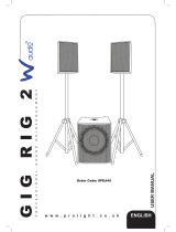
Figure 1: ULTRA-X40 Wide Coverage Loudspeaker
Figure 2: ULTRA-X40 Amplifier and User Panel

ULTRA-X40/42 OPERATING INSTRUCTIONS
11
An optional RMS™ remote monitoring system module
provides comprehensive monitoring of loudspeaker
parameters from a host computer running Compass
®
software.
NOTE: Complete acoustical, electrical and
physical specifications are covered in
Appendix C on page 59.
RIG-READY
The durable trapezoidal enclosure of the ULTRA-X40/42
loudspeaker has a slightly textured black finish. A
powder-coated, round-perforated steel grille provides
protection to the front of the loudspeaker.
The ULTRA-X40/42 includes 11 integral M8 rigging points. It
also includes an integral 35 mm stand mount receptacle
with M20 threads for added stability (Figure 3).
With this versatile integrated rigging, the ULTRA-X40/42 is
ready for a wide variety of applications including those
requiring pole mounting, hanging individually in horizontal or
vertical orientations, or clustering.
Optional rigging accessories include an adjustable 35 mm
pole with M20 slug, a yoke (Figure 4), a U-bracket (Figure 5),
a pinnable link on a channel that allows the hanging of
multiple units from a single pick-up point (Figure 6), a heavy-
duty top bracket capable of suspending multiple
loudspeakers (Figure 7), and cluster plates for vertical
(Figure 7) and horizontal (Figure 8) loudspeaker grouping.
Figure 3: ULTRA-X40 Pole Mount Receptacle
Figure 4: ULTRA-X40 Suspended in an MYA-X40 Yoke Mount
Figure 5: ULTRA-X40 Vertically Held in a MUB-X40 U-Bracket

CHAPTER 1: INTRODUCTION
12
Figure 6: ULTRA-X40 with an MTC-X40 Top Channel for Pick-Up Point
Figure 7: MTB-X40 Suspending two ULTRA-X40 Vertically Using Two
MCP50-x40 Cluster Plates
Figure 8: ULTRA-X40 Horizontally Arrayed Using an MTC-X40 Top
Channel and Two MPC50-X40 Cluster Plates

ULTRA-X40/42 OPERATING INSTRUCTIONS
13
TOTAL SYSTEM APPROACH
The ULTRA-X40 loudspeaker integrates seamlessly with
other Meyer Sound products. With compatible acoustical
and performance characteristics and dedicated QuickFly
rigging hardware, the ULTRA-X40/42 loudspeaker and other
Meyer Sound self-powered loudspeakers can provide
everything needed to design and implement systems for
optimum performance in venues of any size or shape.
TIP: TIP: Meyer Sound MAPP™ acoustical
prediction software allows for quick
determination of the coverage, frequency
response, impulse response, and maximum linear,
undistorted output of Meyer Sound loudspeakers. It
also provides useful rigging information.
In addition to smooth integration with other Meyer Sound
loudspeakers, the ULTRA-X40/42 loudspeaker can be
supplemented with Meyer Sound subwoofers for extended
low-frequency bandwidth and headroom. ULTRA-X40/42
systems can be deployed in combination with the 750-LFC
very compact low-frequency control element (Figure 9),
extending the system frequency response down to 35 Hz, or
the 900-LFC compact low-frequency control element
(Figure 10), which supports frequencies down to 30 Hz.
The ULTRA-X40/42 is supported by Meyer Sound’s MAPP
acoustical prediction program and the Galileo™ GALAXY
Network Platform loudspeaker management system. Once a
Meyer Sound system is designed and installed, its
performance can be confirmed and optimized using a SIM
audio analyzer system.
Figure 9: The 750-LFC Very Compact Low Frequency Control Element
Figure 10: The 900-LFC Compact Low Frequency Control Element

CHAPTER 1: INTRODUCTION
14

15
CHAPTER 2: POWER REQUIREMENTS
The ULTRA-X40/42 loudspeaker combines advanced
loudspeaker technology with equally advanced power
capabilities. Understanding power distribution, voltage and
current requirements, and electrical safety guidelines is critical
for the safe operation of the ULTRA-X40/42.
AC POWER DISTRIBUTION
All components in an audio system (self-powered
loudspeakers, mixing consoles, and processors) must be
properly connected to an AC power distribution system,
ensuring that AC line polarity is preserved and that all
grounding points are connected to a single node or common
point using the same cable gauge (or larger) as the neutral and
line cables.
CAUTION: Make sure the voltage received by
the ULTRA-X40/42 loudspeaker remains within
its 90–264 V AC operating range. In addition, the
ground line must always be used for safety reasons and
the line-to-ground voltage should never exceed
250 V AC (typically 120 V AC from line to ground).
CAUTION: Before applying AC power to any
Meyer Sound self-powered loudspeaker, make
sure that the voltage potential difference between the
neutral and earth-ground lines is less than 5 V AC when
using single-phase AC wiring.
NOTE: Improper grounding of connections
between loudspeakers and the rest of the audio
system may produce noise or hum, or cause serious
damage to the input and output stages of the system’s
electronic components.
120 V AC, 3-Phase Wye System (Single Line)
Line-Neutral-Earth/Ground
Figure 11 illustrates a basic 120 V AC, 3-phase Wye
distribution system with the loudspeaker load distributed
across all three phases, with each loudspeaker connected to a
single line and common neutral and earth/ground lines. This
system delivers 120 V AC to each loudspeaker.
120 V AC, 3-Phase Wye System (Two Lines)
Line-Line-Earth/Ground
Figure 12 illustrates a 120 V AC, 3-phase Wye distribution
system with each loudspeaker connected to two lines and a
common earth/ground line. This configuration is possible
because ULTRA-X40/42 tolerates elevated voltages from the
ground line and does not require a neutral line. This system
delivers 208 V AC to each loudspeaker.
TIP: The 120 V AC, 3-phase Wye system with two
lines is recommended because it allows
loudspeakers to draw less current than with
single-line systems, thereby reducing voltage drop due
to cable resistance. It also excludes the potential of
varying ground to neutral voltages producing an
audible hum.
!
!
Figure 11: 120 V AC, 3-Phase Wye System (Single Line to Loudspeakers)
Figure 12: 120 V AC, 3-Phase Wye System (Two Lines to Loudspeakers)
Neutral
Earth/Ground
Line 1 (120 V AC)
Line 3 (120 V AC)
Line 2 (120 V AC)
Loudspeaker
(120 V AC)
Loudspeaker
(120 V AC)
Loudspeaker
(120 V AC)
Neutral
Earth/Ground
Loudspeaker
(208 V AC)
Loudspeaker
(208 V AC)
Loudspeaker
(208 V AC)
Line 1 (120 V AC)
Line 3 (120 V AC)
Line 2 (120 V AC)

CHAPTER 2: POWER REQUIREMENTS
16
230 V AC, 3-Phase Wye System (Single Line)
Line-Neutral-Earth/Ground
Figure 13 illustrates a basic 230 V AC, 3-phase Wye
distribution system with the loudspeaker load distributed
across all three phases, with each loudspeaker connected
to a single line and common neutral and earth/ground lines.
This system delivers 230 V AC to each loudspeaker.
CAUTION: For 230 V AC, 3-phase Wye
systems, never connect two lines to the AC
input of ULTRA-X40/42, as the resulting voltage
would exceed the upper voltage limit (275 V AC) and
will damage the loudspeaker.
AC CONNECTORS
The ULTRA-X40/42 user panel includes two powerCON 20
connectors (Figure 14), one for AC Input (blue) and one for
AC Loop Output (gray).
AC Input (Blue)
The blue AC Input connector supplies power to
ULTRA-X40/42. The 3-conductor powerCON 20 is rated at
20 A and uses a locking connector that prevents accidental
disconnections. A 10-foot AC power cable, rated at 15 A, is
included with each loudspeaker. If the included AC power
cable is replaced, make sure to use a cable with the
appropriate power plug (on the other end) for the region
where the unit will be operated. ULTRA-X40/42 requires a
grounded outlet. To operate safely and effectively, it is
extremely important that the entire system be properly
grounded.
The AC Input connector also supplies power to any
additional loudspeakers connected to the loudspeaker’s
gray Loop Output connector.
CAUTION: When looping AC power for
loudspeakers, do not exceed the current
capability of the AC Input connector (20 A) or the
included AC power cable (15 A). Consider the total
current draw for all loudspeakers on the circuit,
including the first loudspeaker (Table 1).
AC Loop Output (Gray)
The gray AC Loop Output connector allows multiple
ULTRA-X40/42 to be looped and powered from a single
power source. The 3-conductor powerCON 20 is rated at
20 A and uses a locking connector that prevents accidental
disconnections. For applications that require multiple
ULTRA-X40/42, connect the AC Loop Output of the first
loudspeaker to the AC Input of the second loudspeaker, and
so forth.
The maximum number of loudspeakers that can be looped
from the AC Loop Output connector is determined by the
voltage of the power source, the current draw of the looped
loudspeakers, the circuit breaker rating, and the rating of the
AC power cable connected to the first ULTRA-X40/42
loudspeaker (Table 1).
NOTE: Current draw for ULTRA-X40/42 is
dynamic and fluctuates as operating levels
change. The indicated number of loudspeakers that
can be looped assumes that operating levels are
normal and not such that loudspeakers are
constantly limiting.
ULTRA-X40/42 ships with a gray powerCON 20 cable
mount connector, rated at 20 A, for assembling AC looping
cables. Assembled 1-meter AC looping cables
(PN 28.115.032.03) are also available from Meyer Sound.
Figure 13: 230 V AC, 3-Phase Wye System (Single Line to
Loudspeakers)
Figure 14: AC Input (Left) and AC Loop Output (Right) Connectors
Neutral
Earth/Ground
Line 1 (230 V AC)
Line 3 (230 V AC)
Line 2 (230 V AC)
Loudspeaker
(230 V AC)
Loudspeaker
(230 V AC)
Loudspeaker
(230 V AC)
!
Table 1: Maximum ULTRA-X40/42s that Can Be Looped with AC
Power
Circuit Breaker/
Connector Rating
115 V AC 230 V AC 100 V AC
15 A
6 looped
(7 total)
13 looped
(14 total)
5 looped
(6 total)
20 A
9 looped
(10 total)
18 looped
(19 total)
8 looped
(9 total)
!

ULTRA-X40/42 OPERATING INSTRUCTIONS
17
WIRING AC POWER CABLES
ULTRA-X40/42 ships with a gray powerCON 20 cable mount
connector, rated at 20 A, for assembling AC looping cables
(Figure 15). The pins on the powerCON 20 cable mount
connector are labeled as follows:
• L (Line)
• N (Neutral)
• PE (Protective Earth or Ground)
How AC power cables are wired is determined by the type of
AC power distribution system used (see “AC Power
Distribution” on page 15). When wiring AC power cables for
single-line systems, use one of the wiring schemes shown in
Figure 16 and described in Table 2:
CAUTION: When wiring AC power cables and
distribution systems, it is important to preserve
AC line polarity and connect the earth ground at both
ends of the cable. ULTRA-X40/42 requires a grounded
connection. Always use a grounded outlet and plug. It
is extremely important that the system be properly
grounded to operate safely and properly. Do not
ground-lift the AC cable.
VOLTAGE REQUIREMENTS
ULTRA-X40/42 operates as intended when receiving AC
voltage within the following range:
• 90–264 V AC, 50–60 Hz
If the voltage drops below 90 V, the loudspeaker uses stored
power to continue operating temporarily; the loudspeaker
powers off if the voltage does not return to its operating range.
If the voltage rises above 275 V, the power supply could
become damaged.
CAUTION: The power source for ULTRA-X40/42
should always operate within the required
operating range, at least a few volts from the upper and
lower limits. This approach ensures that AC voltage
variations from the service entry—or peak voltage drops
due to cable runs—will not cause the loudspeaker’s
amplifier to cycle on and off or cause damage to the
power supply.
CURRENT REQUIREMENTS
Current draw for loudspeakers is dynamic and fluctuates as
operating levels change. Because different cables and circuit
breakers heat up at varying rates, it is important to understand
the following types of current ratings and how they affect
circuit breaker and cable specifications.
• Idle Current — The maximum rms current during idle
periods.
• Maximum Long-Term Continuous Current — The
maximum rms current during a period of at least
10 seconds. The maximum long-term continuous current is
used to calculate temperature increases for cables and to
ensure that the size and gauge of each cable conforms to
electrical code standards. This current rating is also used
to select appropriately rated, slow-reacting thermal
breakers, which are recommended for loudspeaker power
distribution. In addition, the maximum long-term
continuous current can be used to calculate the AC
looping capability for ULTRA-X40/42 loudspeakers.
• Burst Current — The maximum rms current during a
period of around 1 second. The burst current is used as a
rating for magnetic breakers. It is also used for calculating
the peak voltage drop in long AC cable runs according to
the following formula:
V pk (drop) = I pk x R (cable total)
• Maximum Instantaneous Peak Current — A rating for
fast-reacting magnetic breakers.
Figure 15: powerCON20Cable Mount Connector
Figure 16: AC Wiring Scheme
Table 2: AC Wiring Scheme
Wire Color Attach to the
Following
Terminal
U.S. / Canada
60 Hz
European
50 Hz
Black Brown Hot or live (L)
White Blue Neutral (N)
Green Green and Yellow
Protective earth / ground
(E or PE)
L
N
PE
SIDE FRONT REAR
U.S./Canada, 60 Hz
Black (L)
Europe, 50 Hz
Green (E)
White (N)
Brown (L)
Blue (N)
Green/
yellow (E)
!
!

CHAPTER 2: POWER REQUIREMENTS
18
Use the information in Table 3 to select the appropriate
cable gauge and circuit breaker ratings for the system’s
operating voltage.
The minimum electrical service amperage required by a
loudspeaker system is the sum of the maximum long-term
continuous current for all loudspeakers. An additional
30 percent above the combined Maximum Long-Term
Continuous amperages is recommended to prevent peak
voltage drops at the service entry.
NOTE: For best performance, the AC cable
voltage drop should not exceed 10 V
(10 percent at 115 V and 5 percent at 230 V). This
approach ensures that the AC voltage variations from
the service entry—or peak voltage drops due to longer
cable runs—do not cause the amplifier to cycle on and
off.
INTELLIGENT AC POWER SUPPLY
ULTRA-X40/42’s Intelligent AC™ power supply
automatically selects the correct operating voltage (allowing
the loudspeaker to be used internationally without manually
setting voltage switches), eliminates high inrush currents
with soft-start power up, suppresses high-voltage transients
up to several kilovolts, filters common mode and differential
mode radio frequencies (EMI), and sustains operation
temporarily during low-voltage periods.
Powering on ULTRA-X40/42
When powering on ULTRA-X40/42, the following startup
events take place over several seconds.
1. Audio output is muted.
2. Voltage is detected and the power supply mode is auto-
matically adjusted as necessary.
3. The power supply ramps up.
4. On the user panel, the Active/Status LED flashes multiple
colors successively.
5. The Active/Status LED turns solid green, indicating the
loudspeaker is unmuted and ready to output audio.
CAUTION: If the Active/Status LED does not
turn solid green, or the ULTRA-X40/42 does
not output audio after 10 seconds, remove AC power
immediately and verify that the voltage is within the
required range. If the problem persists, contact
Meyer Sound Technical Support.
Table 3: ULTRA-X40/42 Current Draw
Current Draw 115 V AC 230 V AC 100 V AC
Idle 0.27 A rms 0.25 A rms 0.29 A rms
Maximum Long-Term
Continuous
1.9 A rms 1.0 A rms 2.2 A rms
Burst 3.1 A rms 1.5 A rms 3.4 A rms
Maximum Instantaneous
Peak
6.9 A peak 3.4 A peak 7.9 A peak
!

ULTRA-X40/42 OPERATING INSTRUCTIONS
19
ELECTRICAL SAFETY GUIDELINES
Make sure to observe the following important electrical and
safety guidelines.
• The powerCON 20 connector should not be engaged or
disengaged when under load or energized. Either
de-energize or disconnect the other end of the cable.
• ULTRA-X40/42 requires a grounded outlet. Always use a
grounded outlet and plug.
• Do not use a ground-lifting adapter or cut the AC cable
ground pin.
• Do not exceed the current capability of the 20 A AC Input
connector for the loudspeaker. When looping
loudspeakers, consider the total current draw for all
loudspeakers on the circuit, including the first loudspeaker.
• Make sure the AC power cable for the loudspeaker has the
appropriate power plug (on the other end) for the area in
which you will operate the loudspeaker. In addition, the AC
power cable must be rated for the total current draw of all
loudspeakers looped from the power source.
• Do not operate the unit if the power cable is frayed or
broken.
• Keep all liquids away from ULTRA-X40/42 loudspeakers to
avoid hazards from electrical shock.
Earth ground
Chassis ground

CHAPTER 2: POWER REQUIREMENTS
20
/