Page is loading ...

Contents: Page:
Part 2: Installation Instructions Cl. 971-805, -825
1. Components of the Sewing Unit
. . . . . . . . . . . . . . . . . . . . . . . . . . . . . . . . . 3
2. Assembling the Sewing Unit
2.1 Attaching the Sewing Head on the Basic Machine . . . . . . . . . . . . . . . . . . . . . . . . 4
2.2 Attaching the Trimming Head on the Basic Machine . . . . . . . . . . . . . . . . . . . . . . . 5
2.3 Attaching the Material Holder . . . . . . . . . . . . . . . . . . . . . . . . . . . . . . . . . . . . 6
2.4 Connecting the Microcontrol Control Unit. . . . . . . . . . . . . . . . . . . . . . . . . . . . . . 7
2.5 Attaching the Yarn Stand . . . . . . . . . . . . . . . . . . . . . . . . . . . . . . . . . . . . . . 7
3. Aligning the Sewing Unit
. . . . . . . . . . . . . . . . . . . . . . . . . . . . . . . . . . . . . 8
4. Connecting the Stacker to the Sewing Unit
. . . . . . . . . . . . . . . . . . . . . . . . . . . 8
6. Electrical Connections for the Sewing Unit
6.1 Setting the Motor Protection Switch . . . . . . . . . . . . . . . . . . . . . . . . . . . . . . . . 9
6.3 Checking the Direction of Rotation . . . . . . . . . . . . . . . . . . . . . . . . . . . . . . . . . 9
7. Pneumatic Connection
. . . . . . . . . . . . . . . . . . . . . . . . . . . . . . . . . . . . . . . 10
8. Commissioning
. . . . . . . . . . . . . . . . . . . . . . . . . . . . . . . . . . . . . . . . . . . 10

1. Components of the Sewing Unit
Upon delivery the sewing unit is composed of the following
components:
–
Basic machine
–
Sewing machine
–
Trimmer
–
Material holder
–
Yarn stand
–
Control panel
–
Pedal with foot switches
–
Small parts with the accessories
–
Stacker (optional equipment)
–
Tape roll holder (optional equipment)
–
Suction unit (optional equipment)
3

2. Assembling the Sewing Unit
2.1 Attaching the Sewing Head on the Basic Machine
Caution Risk of Injury!
Attach the sewing head with helpers or using suitable aids
1. Attaching the Sewing Head
–
Bring the two swing arm parts 1 and 5 together and connect with
the shaft 2.
–
Slightly tighten the attachment nuts.
–
Turn shaft 2 until the interval "X" is the same at the top and bottom.
In this position the clearance between needle hole mushroom 6
and Delrin of the material holder should be 0.2 mm. If necessary,
turn shaft 2 a little.
–
Only tighten the upper and lower slotted nuts so far that the
bearing has no play.
–
Secure the slotted nuts against turning by folding over a lock
washer lip.
–
Tighten clamping screws 3 and 4.
2. Connecting the Wiring
–
Lay the drive motor connection wiring through the guide in the
frame to the control panel.
–
Lay the wiring for the thread monitor in the curve to the swing arm
part 1 and push through the slot 5.
6
1
2
3
45
6
4

2.2 Attaching the Trimming Head on the Basic Machine
Caution Risk of Injury!
Attach the trimming head with helpers or using suitable aids
–
Attach the trimming head as described in Section 2.1.
Care should be taken that the clearance between the guide piece 1
and the Delrin 2 of the clamp is 0.3 - 0.5 mm.
–
For correction loosen screws 3 and 4 and turn the spindle 5
accordingly.
–
Guide the motor connection wiring through the frame (screw union)
to the control panel.
–
The connections are marked in the control panel. (See also
Hook-Up Diagram 9870 971001 B Sheet 1/2)
12
5
4
3
5

2.3 Attaching the Material Holder
Attach the holder to the turntable and thereby give attention to the
following items:
With adjustable material holders:
–
The numbers 1 (1, 2, 3, 4, etc.) on the holders correspond to their
position in the turntable.
Tighten the mounting screws 6 with the special wrench 2.
With non-adjustable material holders:
–
The pins 3 and 4 underneath the holder must lay onto the
perimeter of the rotary disk.
Tighten the mounting screws with the special wrench 5.
1
6
3
4
5
2
6

2.4 Connecting the Microcontrol Control Unit
–
Place the control unit on the mounting plate (snap connectors)
–
Connecting the wiring:
Attention!
Carefully insert the plugs into the back of the control unit. In as far
as these are present, take care that the designations on the wiring
and on the back are the same.
Also pay attention to the provision of the plugs with contact pins or
sockets, as well as their number and arrangement.
–
Tighten the screw fastenings on the plugs.
2.5 Attaching the Yarn Stand
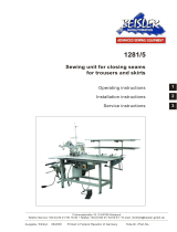
Arrangement and position of the yarn stand can be seen in the cover
photo.
–
Insert the stand and screw on the nut under the mounting plate.
–
The yarn roll holder and unwinding arm must lie above each other.
7

3. Aligning the Sewing Unit
–
Place the disks with rubber washers under the four feet. (These are
in the accessories package)
–
Set the height so that the cast body has sufficient clearance to the
floor.
For this turn the 4 feet appropriately.
–
Place a level gauge on the stand and align the sewing unit with the
4 feet. If no level gauge is available align the sewing unit so that
the slewable sewing head does not move out of position.
4. Connecting the Stacker with the Sewing Unit.
1. Attaching the stacker to the sewing unit.
–
Loosen clamping lever 2.
–
Push the stacker toward the sewing unit and guide the mounting
rail 3 into the mounting.
–
Tighten clamping lever 2.
2. Setting the height of the stacker to the sewing unit.
The placement plate 4 of the stacker should have a clearance of
approx. 3 mm to the underside of the material holder.
–
Loosen screw 5 and set the height of the stacker.
3. Operation without the stacker.
–
The standard setting of the controls is for "Operation with Stacker".
If no stacker is attached this must be changed in the controls.
See Instructions for the Microcontrol Control Unit Chapter
"2.2 Operating Elements in the Controls"
3
4
123
5
8

6. Electrical Connections for the Sewing Unit
For Special Attention!
The mains voltage and the nominal voltage on the motor rating plate
must agree.
All work on the electrical components are only to be conducted by
authorized personnel and with the mains plug pulled.
Please observe the general safety notes.
6.1 Setting the Motor Protection Switch
The motor protection switch 1 must be set appropriate to the mains
voltage.
Setting for 3 x 220V = 4,8 A
3 x 230V = 4,8 A
3 x 240V = 5,0 A
3 x 380V = 2,5 A
3 x 400V = 2,5 A
3 x 415V = 2,7 A
6.2 Checking the Direction of Rotation
–
Turn on the main switch.
–
Turn on automatic operation for a short period with the right pedal
and then off again.
–
The turntable must turn counterclockwise.
If the direction of rotation is
not
correct 2 phases in the mains plug
must be interchanged.
1
9

7. Pneumatic Connection
Attention!
For a flawless functioning of the pneumatic control procedures, the
following notes are to be observed.
The compressed air supply must be so designed that at the moment of
greatest air consumption the minimum operating pressure does
not
fall
below 5 bar.
–
Connect hose 1 of the sewing unit to the compressed air supply (7
- 10 bar).
Operating pressure = 5 bar
–
To set the pressure lift knob 2 and turn.
- To the left = Reduce pressure
- To the right = Increase pressure
8. Commissioning
Trial run
–
First conduct a trial run with material to check the correct function
sequence.
First sewing start
–
Start automatic operation and stop again, when a material holder
is in front of the sewing head.
–
Thread the needle and hook threads.
–
Place material in the clamp at the sewing head. Press the opening
lever down manually.
–
Sew the first stitches manually.
–
Place material in the next clamp.
–
Start automatic operation.
2
1
10
/


